Page 1685 of 2248
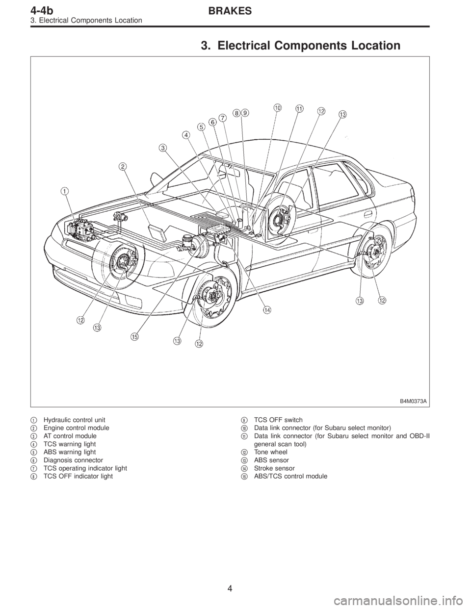
3. Electrical Components Location
B4M0373A
�1Hydraulic control unit
�
2Engine control module
�
3AT control module
�
4TCS warning light
�
5ABS warning light
�
6Diagnosis connector
�
7TCS operating indicator light
�
8TCS OFF indicator light�
9TCS OFF switch
�
10Data link connector (for Subaru select monitor)
�
11Data link connector (for Subaru select monitor and OBD-II
general scan tool)
�
12Tone wheel
�
13ABS sensor
�
14Stroke sensor
�
15ABS/TCS control module
4
4-4bBRAKES
3. Electrical Components Location
Page 1687 of 2248
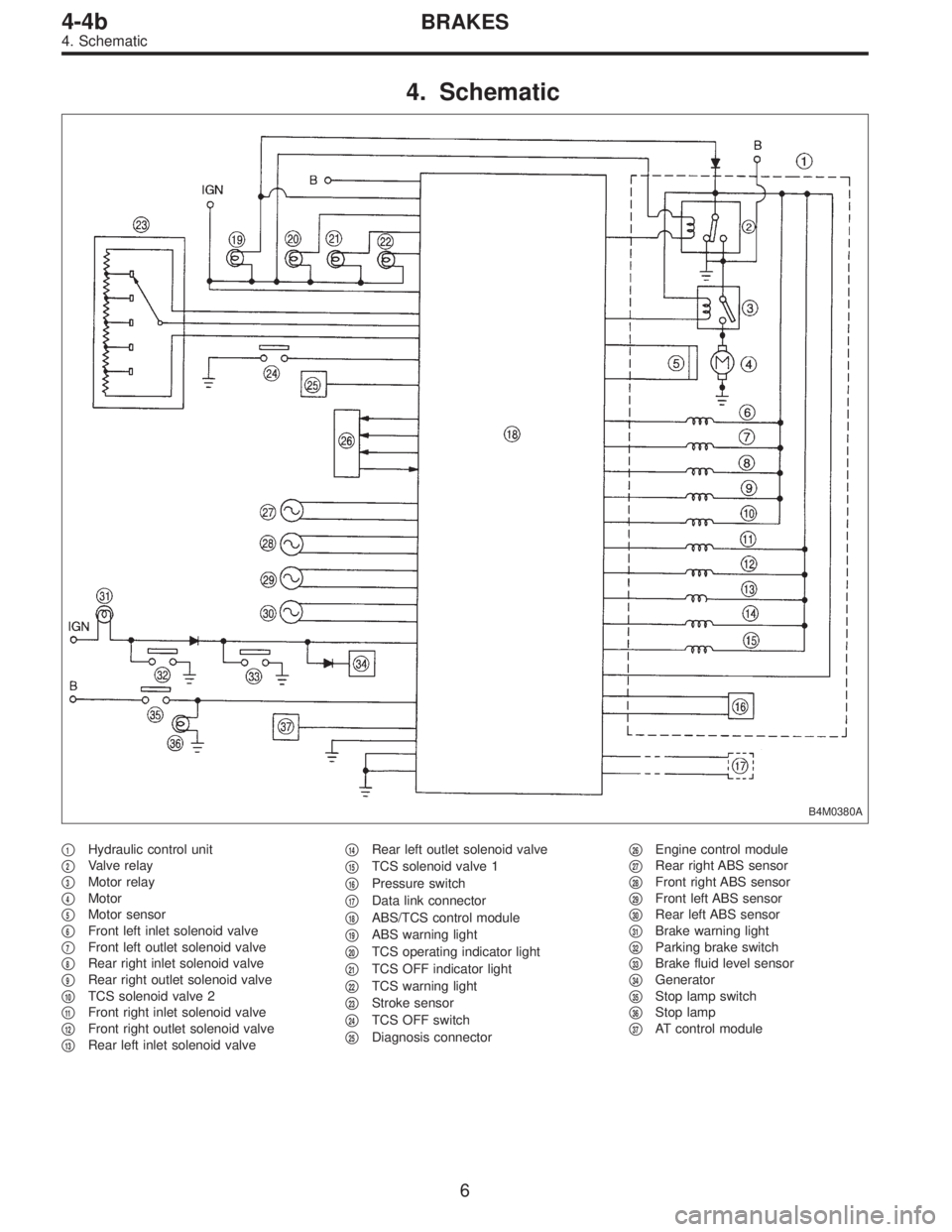
4. Schematic
B4M0380A
�1Hydraulic control unit
�
2Valve relay
�
3Motor relay
�
4Motor
�
5Motor sensor
�
6Front left inlet solenoid valve
�
7Front left outlet solenoid valve
�
8Rear right inlet solenoid valve
�
9Rear right outlet solenoid valve
�
10TCS solenoid valve 2
�
11Front right inlet solenoid valve
�
12Front right outlet solenoid valve
�
13Rear left inlet solenoid valve�
14Rear left outlet solenoid valve
�
15TCS solenoid valve 1
�
16Pressure switch
�
17Data link connector
�
18ABS/TCS control module
�
19ABS warning light
�
20TCS operating indicator light
�
21TCS OFF indicator light
�
22TCS warning light
�
23Stroke sensor
�
24TCS OFF switch
�
25Diagnosis connector�
26Engine control module
�
27Rear right ABS sensor
�
28Front right ABS sensor
�
29Front left ABS sensor
�
30Rear left ABS sensor
�
31Brake warning light
�
32Parking brake switch
�
33Brake fluid level sensor
�
34Generator
�
35Stop lamp switch
�
36Stop lamp
�
37AT control module
6
4-4bBRAKES
4. Schematic
Page 1688 of 2248
Front left wheel P7 1�")
5. Control Module I/O Signal
1. I/O SIGNAL VOLTAGE
Contents Connector No. Terminal No.Input/Output signals
Measured value and measuring conditions
ABS
sensor
(Wheel
speed
sensor)Front left wheel P7 1—11 0.12—1 V (When it is 10 Hz.)
Front right wheel P6 8—16 0.12—1 V (When it is 10 Hz.)
Rear left wheel P6 7—15 0.12—1 V (When it is 10 Hz.)
Rear right wheel P7 2—12 0.12—1 V (When it is 10 Hz.)
Hydraulic
unitSolenoid
valveFront left outlet P4 1—GND
10—14 V when the valve is OFF.
Less than 1.5 V when the valve is ON. Front right outlet P5 3—GND
Rear left outlet P5 8—GND
Rear right outlet P4 3—GND
Front left inlet P4 2—GND
10—14 V when the valve is OFF.
Less than 1.0 V when the valve is ON. Front right inlet P5 2—GND
Rear left inlet P5 7—GND
Rear right inlet P4 4—GND
TCS 1 P4 5—GND
10—14 V when the valve is OFF.
Less than 1.0 V when the valve is ON.
TCS 2 P5 6—GND
Valve power supply P6 6—GND Ignition switch ON, 10—14 V
Valve relay power supply P6 1—GNDLess than 1.2 V when IGN is ON.
10—14 V when the system is down.
Motor relay power supply P6 9—GNDLess than 1.0 V when the motor is ON.
10—14 V when the motor is OFF.
Motor sensor signalsP7 3—GNDCyclic waveform of more than 180 Hz
when the motor across terminals is ON.
Less than 70 Hz when the motor is OFF. P7 13—GND
Pressure switch P7 6—GNDH/L toggle signal with the brake pedal off
(Cycle 14 mS, H: 10—14 V, L: less than
0.7 V). 10—14 V with the brake pedal
depressed.
Pedal
stroke
sensorOutput signals P7 5—GND 0.7—0.9 V with the brake pedal off.
Power supply P7 4—14 5±0.4 V
Stop light
switchSwitch P7 7—GNDLess than 2 V when the stop light is off.
10—12 V when the stop light is on.
Switch test signal P7 18—GNDH/L toggle signal with the brake pedal off
(Cycle 14 mS, H: 10—12 V, L: less than
0.7 V). Less than 2 V with the brake pedal
depressed.
TCS OFF switch P7 16—GNDLess than 2.0 V with the switch pressed
and 10—12 V with it released.
Indicator
lightTCS OFF P6 10—GND
Less than2Vwhenthelight is on and
10—12 V when it is off. TCS operation P6 11—GND
TCS warning P6 3—GND
ABS warning P6 2—GND
7
4-4bBRAKES
5. Control Module I/O Signal
Page 1689 of 2248
P6 14—GNDLess than 0.7 V whe")
Contents Connector No. Terminal No.Input/Output signals
Measured value and measuring conditions
TCS
control
unit ECM
commun-
icationTCS,ECM communication
(torque command)P6 14—GNDLess than 0.7 V when the vehicle stands
still.
TCS,ECM communication
(torque command)P6 5—GNDLess than 5 V when the vehicle stands
still.
TCS,ECM communication
(TCS operates)P6 12—GND4—5.4 V when TCS controls no
operations. Less than 0.7 V when it
controls operations.
ECM,TCS communication
(engine control)P6 4—GNDH/L toggle signal with the accelerator
pedal off (Cycle 20 mS, H: 10—14 V, L:
less than 0.7 V). Less than 2.0 V with the
accelerator pedal depressed. Also when
TCS OFF indicator light comes on by TCS
OFF switch.
ABS operation signal P6 13—GND10—14 V when the ABS control does not
operate still and less than 0.7 V when
ABS operates.
Fluid level sensor P7 20—GNDLess than2VwhenIGNisONand10—
14 V when idling.
Select
monitorData is received. P7 9—GND 4—4.5 V when no data is received.
Data is sent. P7 19—GND 4—4.5 V when no data is sent.
Diagnosis connector P7 8—GND 10—14 V when IGN is ON.
Power
supplyIgnition P5 1—GND 10—14 V when IGN is ON.
Battery P5 4—GND 10—14 V
Grounding
linePower P5 5—body 1Ωor less
Digital P7 15—body 1Ωor less
Power P4 6—body 1Ωor less
8
4-4bBRAKES
5. Control Module I/O Signal
Page 1697 of 2248

C: INSPECTION MODE
The on-board diagnosis system is designed to detect prob-
lems while the vehicle is being driven. If a problem is found,
the ABS and TCS warning light will illuminate to inform the
driver of the occurrence of a problem. When the warning
light is on, the ABS/TCS system will be inactive and the
normal braking function will work. It is possible for the most
recent trouble code and history of problem to be stored in
memory until cleared.
B4M0082C
D: TROUBLE CODES
When on-board diagnosis of the ABS/TCS control module
detects a problem, the information will be stored in the EEP
ROM as a trouble code. (Stored codes will stay in memory
until they are cleared.)
1. CALLING UP A TROUBLE CODE
1) Take out diagnosis connector from side of driver’s seat
heater unit.
2) Turn ignition switch OFF.
3) Connect diagnosis connector terminal No. 4 to diagno-
sis terminal.
4) Turn ignition switch ON.
5) TCS warning light is set in the diagnostic mode and
blinks to identify trouble code.
6) After the start code (11) is shown, the trouble codes will
be shown in order of the last information first.
NOTE:
When there are no trouble codes in memory, only the start
code (11) is shown.
B4M0383A
16
4-4bBRAKES
6. Diagnostics Chart for On-board Diagnosis System
Page 1716 of 2248

8. Diagnostics Chart with Trouble Code
A: LIST OF TROUBLE CODE
Trouble code Contents of diagnosis Ref. to 4-4b
11Start code
�Trouble code is shown after start code.
�Only start code is shown in normal condition.—
21
Faulty ABS sensor
(Open circuit or short circuit)Front right wheel speed sensor
[T8B0] 23 Front left wheel speed sensor
25 Rear right wheel speed sensor
27 Rear left wheel speed sensor
22
Faulty ABS sensor
(Faulty ABS sensor signal)Front right wheel speed sensor
[T8C0] 24 Front left wheel speed sensor
26 Rear right wheel speed sensor
28 Rear left wheel speed sensor
31
Faulty solenoid valve circuit(s) in hydraulic
unitFront right inlet valve [T8D0]
32 Front right outlet valve [T8E0]
33 Front left inlet valve [T8D0]
34 Front left outlet valve [T8E0]
35 Rear right inlet valve [T8D0]
36 Rear right outlet valve [T8E0]
37 Rear left inlet valve [T8D0]
38 Rear left outlet valve [T8E0]
41 Faulty ABS/TCS control module [T8F0]
42 Source voltage is high.[T8G0]
43 Faulty engine control module communication cables [T8H0]
51 Faulty valve relay[T8I0]
52 Faulty motor, motor sensor and/or motor relay [T8J0]
54 Faulty stroke sensor and/or stop light switch [T8K0]
57 Faulty fluid level sensor[T8L0]
58 Faulty pressure switch[T8M0]
61
Faulty solenoid valve circuit(s) in hydraulic
unitTCS 1 valve [T8D0]
62 TCS 2 valve [T8D0]
35
4-4bBRAKES
8. Diagnostics Chart with Trouble Code
Page 1721 of 2248
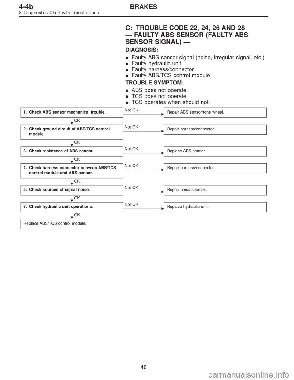
C: TROUBLE CODE 22, 24, 26 AND 28
—FAULTY ABS SENSOR (FAULTY ABS
SENSOR SIGNAL)—
DIAGNOSIS:
�Faulty ABS sensor signal (noise, irregular signal, etc.)
�Faulty hydraulic unit
�Faulty harness/connector
�Faulty ABS/TCS control module
TROUBLE SYMPTOM:
�ABS does not operate.
�TCS does not operate.
�TCS operates when should not.
1. Check ABS sensor mechanical trouble.
OK
�Not OK
Repair ABS sensor/tone wheel.
2. Check ground circuit of ABS/TCS control
module.
OK
�Not OK
Repair harness/connector.
3. Check resistance of ABS sensor.
OK
�Not OK
Replace ABS sensor.
4. Check harness connector between ABS/TCS
control module and ABS sensor.
OK
�Not OK
Repair harness/connector.
5. Check sources of signal noise.
OK
�Not OK
Repair noise sources.
6. Check hydraulic unit operations.
OK
�Not OK
Replace hydraulic unit.
Replace ABS/TCS control module.
�
�
�
�
�
�
40
4-4bBRAKES
8. Diagnostics Chart with Trouble Code
Page 1726 of 2248
5. CHECK SOURCES OF SIGNAL NOISE.
1) Check that the mobile phone, personal radio and other
wireless apparatus are correctly installed.
2) Check that the antenna and other possible noise
sources are distant enough from the sensor harness.
3) Check that the sealed wires of the front harness sensor
(in the engine room) are securely grounded.
4) Check that between ABS/TCS control module and the
rear sensor harness has the correct twist pitch.
Twist pitch:
25 mm (0.98 in) or less
6. CHECK HYDRAULIC UNIT OPERATIONS.
1) Operate the ABS sequence control and check that the
brake fluid pressure at the malfunctioning brake line
increases and decreases properly.
45
4-4bBRAKES
8. Diagnostics Chart with Trouble Code
 Check that the mobile phone, personal radio and other
wireless apparatus are correctly installed.
2) Check that the antenna and other possible noise
sources are di")