1995 NISSAN ALMERA N15 engine oil
[x] Cancel search: engine oilPage 774 of 1701
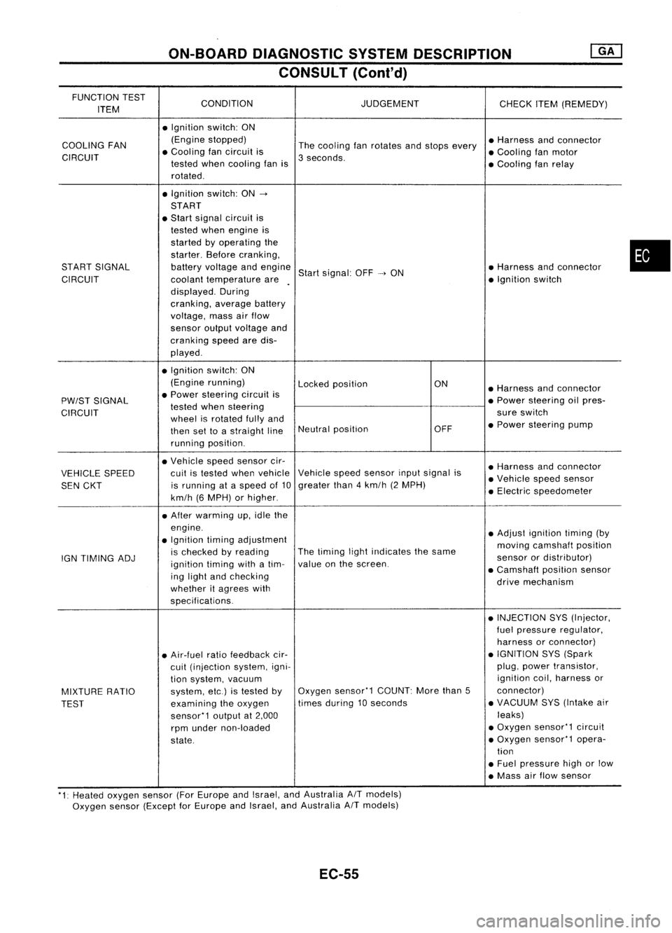
ON-BOARDDIAGNOSTIC SYSTEMDESCRIPTION
CONSULT (Conl'd)
FUNCTION TEST
CONDITION JUDGEMENT
ITEM CHECK
ITEM(REMEDY)
• Ignition switch:ON
COOLING FAN (Engine
stopped)
Thecooling fanrotates andstops every •
Harness andconnector
CIRCUIT •
Cooling fancircuit is
3seconds. •
Cooling fanmotor
tested whencooling fanis
•Cooling fanrelay
rotated .
• Ignition switch:ON-.
START
• Start signal circuit is
tested whenengine is
started byoperating the
starter. Beforecranking,
START SIGNAL batteryvoltage andengine
Startsignal: OFF-.ON •
Harness andconnector
CIRCUIT coolanttemperature are •
Ignition switch
displayed. During
cranking, averagebattery
voltage, massairflow
sensor outputvoltage and
cranking speedaredis-
played .
• Ignition switch:ON
(Engine running)
Lockedposition ON
•Harness andconnector
PW/ST SIGNAL •
Power steering circuitis
•Power steering oilpres-
tested whensteering
CIRCUIT wheelisrotated fullyand sure
switch
then settoastraight lineNeutral
position OFF•
Power steering pump
running position.
• Vehicle speedsensor cir-
•Harness andconnector
VEHICLE SPEED cuit
istested whenvehicle Vehicle
speedsensor inputsignal is
•Vehicle speedsensor
SEN CKT is
running ataspeed of10 greater
than4km/h (2MPH)
•Electric speedometer
km/h (6MPH) orhigher .
• After warming up,idle the
engine. •Adjust ignition timing(by
• Ignition timingadjustment
movingcamshaft position
IGN TIMING ADJ is
checked byreading The
timing lightindicates thesame
sensorordistributor)
ignition timingwithatim- value
onthe screen.
•Camshaft positionsensor
ing light andchecking
drivemechanism
whether itagrees with
specifications.
•INJECTION SYS(Injector,
fuel pressure regulator,
harness orconnector)
• Air-fuel ratiofeedback cir- •
IGNITION SYS(Spark
cuit (injection system,igni- plug,
power transistor,
tion system, vacuum ignition
coil,harness or
MIXTURE RATIO system,
etc.)istested byOxygen
sensor'1 COUNT:Morethan5 connector)
TEST examining
theoxygen times
during 10seconds •
VACUUM SYS(Intake air
sensor'1 outputat2,000 leaks)
rpm under non-loaded •
Oxygen sensor'1 circuit
state. •
Oxygen sensor'1 opera-
tion
• Fuel pressure highorlow
• Mass airflow sensor
'1: Heated oxygen sensor(ForEurope andIsrael, andAustralia AITmodels)
Oxygen sensor(Except forEurope andIsrael, andAustralia
A/T
models)
EC-55
•
Page 775 of 1701

ON-BOARDDIAGNOSTIC SYSTEMDESCRIPTION
CONSULT (Cont'd)
FUNCTION TEST
CONDITION JUDGEMENTCHECKITEM(REMEDY)
ITEM
•After warming up,idle the
engine .
• Injector operation ofeach •Injector circuit(Injector,
cylinder isstopped one harnessorconnector)
after another, andresult-
Difference inengine speedisgreater •
Ignition circuit(Spark
POWER BALANCE ant
change inengine rota-
than25rpm before andafter cutting off plug,
power transistor,
lion isexamined toevalu-
theinjector ofeach cylinder. ignition
coil,harness or
ate combustion ofeach connector)
cylinder. (Thisisonly dis- •Compression
played formodels wherea •
Valve timing
sequential multiportfuel
injection systemisused.)
• After warming up,idle the
•Harness andconnector
engine. •IACV-AAC valve
• IACV-AAC valvesystem is
Difference inengine speedisgreater •
Air passage restriction
IACV-AACIV testedbydetecting change
than150rpm between whenvalveopen- betweenairinlet and
SYSTEM inengine speedwhen
ingisat 80% andat20%. IACV-AACvalve
IACV-AAC valveopening
•IAS (Idle adjusting screw)
is changed to0%, 20%
and 80%. adjustment
EC-56
Page 791 of 1701
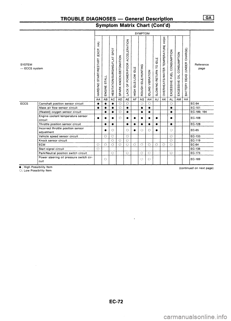
TROUBLEDIAGNOSES -General Description
Symptom MatrixChart(Cont'd)
SYMPTOM
:I:
Z
C)
~
0
I
:I:
i=
UJ
c.:
I-
«
a:
[ij'
a:
:J
u
0
UJ
I-
Z
C)
X
ll.
--l
«
0
z
a:
~
(f)
UJ
a:i=
0
«
I-
z
U
UJ
ll.
i=
:I:
I-
«
0
u
UJ
ll.
:2
ll.
U
a:
--l
i=
«
--l
:2
9
:J
:2
«
u.
«
a:
UJ
(f)
a:
SYSTEM
I-
a
z
:J
UJ
Reference
(f)
0
C)
0
I-
Z
(f)
Cl
- ECCS system
UJ
z
0
0
w
Z
I-
a:
0
z
z
page
a:
c;
l-
ll.
--l
i=
w
u
0
UJ
9
z
z
2-
i==:
a:
Cl
ii:
z
0
a:
I-
--l
U
a::
:J
l2
UJ
~
:J
i=
:J
«
UJ
--l
Cl
«
--l
(f)
~
:I:
I-
~
:J
(5
«
I-
--l
Z
U
0
UJ
«
UJ
en
u.
UJ
«
00
--l
a::
(f)
l-
ll.
W
--l
[])
a::
I-
w
W
Cl
0
(f)
0
z
9
;;
0
«
>
>
>-
i=
::.::
u.
--l
Z
0
9
z
UJ
in in
a::
UJ
«
:I:
:I:
a
z
I-
::.::
C)C)
~
(f)
(f)
UJ
a::
::.::
:I:
z
a::
UJ UJ
I-
a::
c;
in
«
u
C)
:J
:J
0
UJ
U U
I-
«
z
UJ
ll.
«
i
0
9
--l
>
X X
«
:I:
w
:I:(f)
--l
a::
(f)
0
UJ UJ
[])
AA ASAC AD AEAFAG AH AJAK ALAM HA
ECCS Camshaft
positionsensorcircuit
•••
0
0
()
0 0
EC-94
Mass airflow sensor circuit
••
•
0
•
••
•
EC-101
(Heated) oxygensensorcircuit
••
0
• •
•
•
EC-189,194
Engine coolant temperature sensor
••
•
0
••
•
•
•
•
EC-108
circuit
Throttle position sensorcircuit
•• ••• ••
•
EC-128
Incorrect throttleposition sensor
•
()
()
•
0
0
•
()
EC-65
adjustment
Vehicle speedsensor circuit
0
C)
()
0
EC-133
Knock sensor circuit
000 0
EC-119
ECM
0
()
0 0
()
0
()
()()
0 0
EC-64
Start signal circuit
0
EC-138
Park/Neutral positionswitchcircuit
0
0
0
0
0
EC-173
Power steering oilpressure switchcir-
0
(J
0
EC-169
cuit
• ;High Possibility Item
0;
Low Possibility Item
EC-72
(continued
onnext page)
Page 792 of 1701
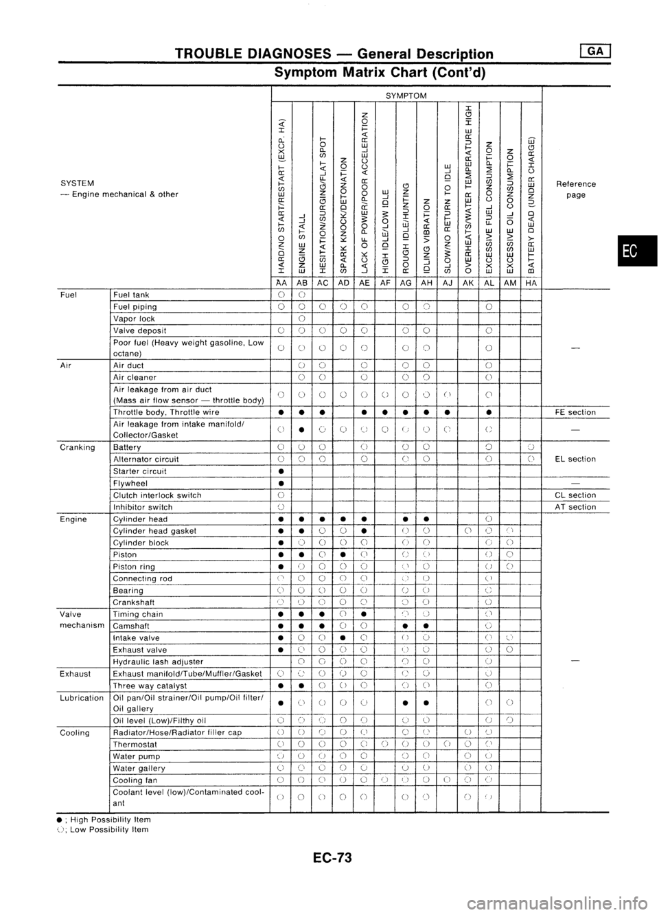
TROUBLEDIAGNOSES -General Description
Symptom MatrixChart(Cont'd)
SYMPTOM
J:
Z
CJ
~
0
I
J:
i=
LU
cL
I-
«
a:
a: ::J
UJ
0
0
LU
I-
Z
CJ
><
D..
-'
«
0
z
a:
~
LU
i=
0
z
0
a:
«
I-
0
0
LULU
D..
i=
J:
I-
«
-'
D..
:2
D..
0
0:
-'
i=
«
9
:2
::J
:2
SYSTEM
«
LL
«
0:
LU
C/J
a:
I-
0
Z
0
CJ
0
I-
Z
::J
LU
Reference
C/J
0
C/J
0
- Engine mechanical
&
other
z
0
LU
Z
I-
0
LU
I-
-'
0:
Z
Z
page
0:
(3
LU
D..
9
i=
z
Z
LU
0
0
2-
;:::
a:
0
a:
z
0
a:
I-
-'
0
0:
::J
~
LU
5:
::J
i=
::J
«
LU
-'
0
-'
J:
5:
«
-'
C/J
0
5:
0
«
I-
::J
(5
«
I-
Z
W
LU
en
LL
LU
C/J
«
00
-'
-'
a:
a:
0
I-
0
Z
D..
W
CD
I-
LU
LU
0
C/J
i=
~
LL
-'
9
:>
0
«
>
~
>-
z
0
Z
LU
(ij
C/J
a:
LU
«
~
9
J:
J:
0
Z
CJ
~
C/J
C/J
LU
I-
0:
~
CJ
Z
a:
LU LU
I-
(3
(jj
J:
a:
«
0
CJ
::J
:J
0
LU
0 0
I-
«
z
LU
D..
«
0
-'
>
><><
«
J:
LU
J:
C/J
-'
J:
a:
9
C/J
0
LU LU
CD
AA ASAC AD
AEAF
AG AH AJAK ALAM HA
Fuel Fueltank
0
U
Fuel piping
00 0
()
0 00 0
Vapor lock
U
Valve deposit
00 000 00
0
Poor fuel(Heavy weightgasoline, Low
0
C)
0 0
()
00
0
-
octane)
Air Airduct
00 0
00
0
Air cleaner
00
0
0
0
0
Air leakage fromairduct
()
(J
()
()
0
0
0 0
("
)
C'
(Mass airflow sensor -throttle body)
Throttle body,Throttle wire
••• •
••
•• •
FE
section
Air leakage fromintake manifold/
0
•
(~)
0
tJ
0
U
C;
U
-
Collector/Gasket
Cranking Battery
0
U
()
(J
00 0
':J
Alternator circuit
()
0
0
0
(J
0 0
(J
ELsection
Starter circuit
•
Flywheel
•
-
Clutch interlock switch
0
CL
section
Inhibitor switch
()
ATsection
Engine Cylinderhead
••
• •
• •
•
()
Cylinder headgasket
••
0
0
•
U
()
0
()
C'
Cylinder block
•
0
0 0
0
()
(J
0
0
Piston
••
0
•
(J
()
()
()
0
Piston ring
•
U
00
0
U
()
U
()
Connecting rod
('
0
0
00
)
U
(
)
Bearing
(i
0
()
0
()
U
0
C
Crankshaft
Cl
(~)
0 0
()
()
0
0
Valve Timingchain
•••
CJ
•
n
()
('
mechanism Camshaft
•••
0
0
•
•
0
Intake valve
•
0
0
•
0
()
':J
0
l~'
Exhaust valve
•
C)
0
()
()
U
u
()
0
HydraUlic lashadjuster
00
0
0
()
()
0
-
Exhaust Exhaust
manifoldlTube/Muffler/Gasket
C)
c:
()
()
0
U
()
U
Three waycatalyst
••
0
U
0 0
()
0
Lubrication Oil
pan/Oil strainer/Oil pump/Oilfilter/
•
Ci
0 0
0
•
•
()
0
Oil gallery
Oil level (Low)/Filthy oil
()
0
()
()()
(J
0
U
()
Cooling Radiator/Hose/Radiator
fillercap
()
0 0
()
()
C)
U
U
()
Thermostat
00
0
0
C)
0
()
00
0
Cl
Water pump
u
0
U
0
0
()
Ci
C)
U
Water gallery
U
()
0
()
0 0
U
0
U
Cooling fan
0
()
CJ
U
0
U
I)
U
()
CJ
(i
Coolant level(low)/Contaminated cool-
U
0
0 0
0
00
()
)
ant
• ;High Possibility Item
U;
Low Possibility Item
EC-73
•
Page 799 of 1701
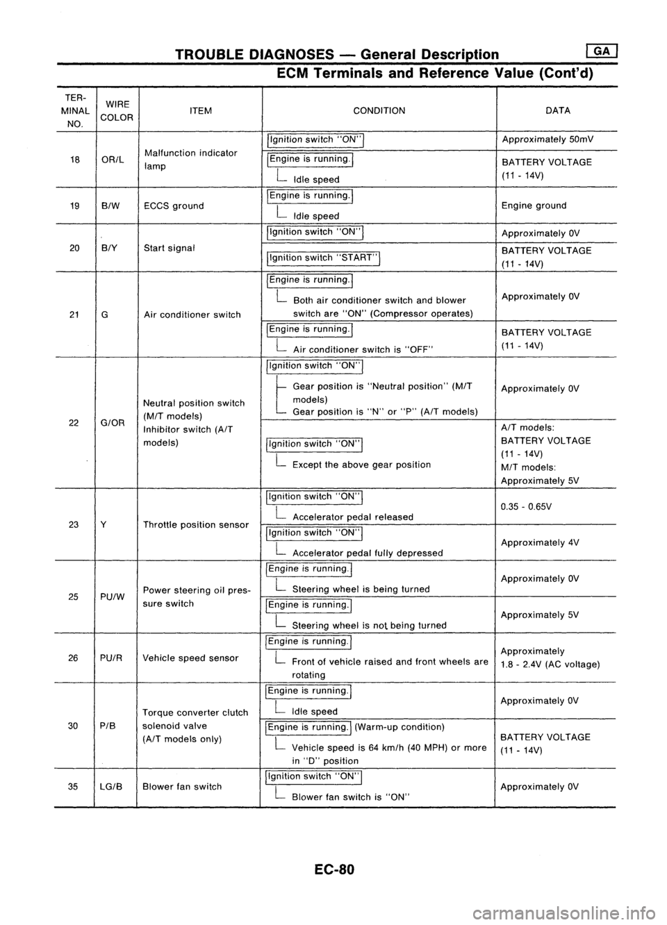
TROUBLEDIAGNOSES -General Description ~
ECM Terminals andReference Value(Cont'd)
TER- WIRE
MINAl ITEM CONDITION DATA
NO. COLOR
/'gnitionswitch"ON'" Approximately
50mV
18 OR/l Malfunction
indicator
I
Engine isrunning.
I
lamp BATTERY
VOLTAGE
L
Idle speed (11.14V)
19 BIW ECCS
ground
I
Engine isrunning.
I
Engineground
L
Idle speed
I'gnition switch"ON"
I
ApproximatelyOV
20 BIY
Startsignal
BATTERYVOLTAGE
I'gnition switch"5TART"
I
(11-14V)
I
Engine isrunning.
I
L
Both airconditioner switchandblower Approximately
OV
21 G Airconditioner switch switch
are"ON" (Compressor operates)
IEngine isrunning.
I
BATTERYVOLTAGE
L
Airconditioner switchis"OFF" (11
-14V)
I'gnition switch"ON'"
t
Ge.,
po,"'on "
"Ne"".1
po,ltlon"
(MIT
Approximately OV
Neutral position switch models)
(M/T
models) Gear
position is"N" or"P"
(A/T
models)
22
G/OR
Inhibitorswitch
(A/T AIT
models:
models) llgnitionswitch"ON'" BATTERY
VOLTAGE
L
Except theabove gearposition (11
-14V)
M/T
models:
Approximately 5V
Ilgnition switch"ON"
I
0.35-0.65V
L
Accelerator pedalreleased
23 Y Throttleposition sensor
!'gnitionswitch"ON"
I
L
Accelerator pedalfullydepressed Approximately
4V
/Engine isrunning.1
ApproximatelyOV
25 Pu/W Power
steering oilpres-
L
Steering wheelisbeing turned
sure switch
IEngineisrunning.1
L
Steering wheelisnot being turned Approximately
5V
I
Engine isrunning.
I
Approximately
26 PUIR Vehiclespeedsensor
L
Front ofvehicle raisedandfront wheels are
1.8-2.4V (ACvoltage)
rotating
I
Engine isrunning.
I
ApproximatelyOV
Torque converter clutch
L
Idle speed
30 PIB
solenoidvalve
I
Engine isrunning.
I
(Warm-up condition)
(A/T
models only)
L
Vehicle speedis64 km/h (40MPH) ormore BATTERY
VOLTAGE
(11-14V)
in "D" position
35 lG/B Blower
fanswitch I,gnition
switch"ON",
ApproximatelyOV
L
Blower fanswitch is"ON"
EC-80
Page 804 of 1701
![NISSAN ALMERA N15 1995 Service Manual TROUBLEDIAGNOSES -General Description @K]
ECM Terminals andReference Value(Conl'd)
TERMINAL WIRE
NO. COLOR ITEM
CONDITION
DATA
Ilgnition switch"ON"I
ApproximatelyOV
34 BIY Startsignal
pgn](/manual-img/5/57349/w960_57349-803.png "NISSAN ALMERA N15 1995 Service Manual TROUBLEDIAGNOSES -General Description @K]
ECM Terminals andReference Value(Conl'd)
TERMINAL WIRE
NO. COLOR ITEM
CONDITION
DATA
Ilgnition switch\"ON\"I
ApproximatelyOV
34 BIY Startsignal
pgn")
TROUBLEDIAGNOSES -General Description @K]
ECM Terminals andReference Value(Conl'd)
TERMINAL WIRE
NO. COLOR ITEM
CONDITION
DATA
Ilgnition switch"ON"I
ApproximatelyOV
34 BIY Startsignal
pgnitionswitch"START"I BATTERY
VOLTAGE
(11 -14V)
pgnition switch"ON"I
t
"N" or"P" position
(A/T)
OV
Neutral position
(M/T)
Neutral position switchl For
Europe andIsrael
35
G/OR
Approximately5V
Inhibitor switch
llgnitionswitch"ON"1
ExceptforEurope and
. L
Except theabove gearposition Israel
BATTERY VOLTAGE
(11 -14V)
Ilgnition switch"OFF"!
OV
36 B/R Ignition
switch(Except
for Europe)
!Ignitionswitch"ON"I BA
TTERY VOLTAGE
(11 •14V)
37 P/L Throttle
position sensor
Ilgnitionswitch"ON"I
Approximately5V
power supply
38
W/R
Powersupply forECM Ilgnition switch"ON"I BA
TTERY VOLTAGE
47 (11
-14V)
IEngine isrunning.1
L
Both airconditioner switchandblower Approximately
OV
41 Gor GY Air
conditioner switch fan
switch are"ON".
!Engine isrunning.1
BATTERYVOLTAGE
L
Airconditioner switchis"OFF". (11
-14V)
IEngine isrunning.!
OV
PU/W Power
steering oilpres-
L
Steering wheelisbeing turned.
43 sureswitch
IEngineisrunning.1
L
Steering wheelisnot being turned. Approximately
5V
jlgnition switch"OFF"I OV
Ignition switch
44 B/R
(ForEurope) BA
TTERY VOLTAGE
pgnition switch"ON"I
(11-14V)
IEngine isrunning.1
Thermo controlamp.
L
Both airconditioner switchandblower fanApproximately
OV
44 R/L (Except
forEurope and switch
are"ON".
Israel) IEngineisrunning.1
BATTERYVOLTAGE
L
Airconditioner switchis"OFF". (11
-14V)
IEngine isrunning.1
ApproximatelyOV
L
Blower fanswitch is"ON".
45 LG/B
or
Blower fanswitch
G/Y
IEngineisrunning.!
L
Blower fanswitch is"OFF". Approximately
5V
EC-85
•
Page 832 of 1701
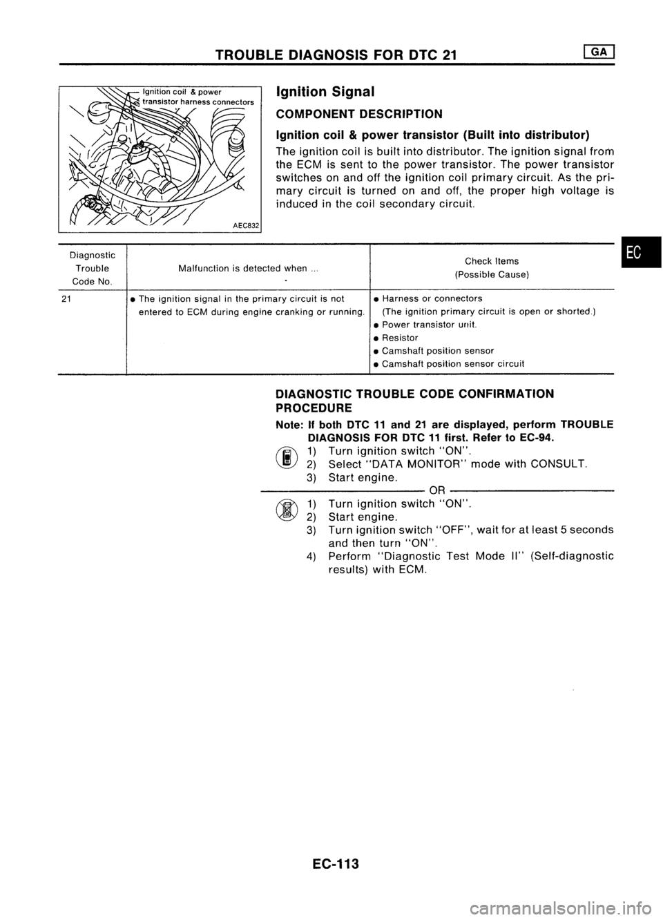
TROUBLEDIAGNOSIS FORDTC21
Malfunction isdetected when...
Diagnostic
Trouble
Code No.
Ignition
coil
&
power
transistor harnessconnectors
AEC832 Ignition
Signal
COMPONENT DESCRIPTION
Ignition coil
&
power transistor (Builtintodistributor)
The ignition coilisbuilt intodistributor. Theignition signalfrom
the ECM issent tothe power transistor. Thepower transistor
switches onand offthe ignition coilprimary circuit.Asthe pri-
mary circuit isturned onand off,the proper highvoltage is
induced inthe coil secondary circuit.
Check Items
(Possible Cause)
•
21
•
The ignition signalinthe primary circuitisnot
entered toECM during engine cranking orrunning. •
Harness orconnectors
(The ignition primary circuitisopen orshorted.)
• Power transistor unit.
• Resistor
• Camshaft positionsensor
• Camshaft positionsensorcircuit
DIAGNOSTIC TROUBLECODECONFIRMATION
PROCEDURE
Note: Ifboth DTC11and 21are displayed, performTROUBLE
DIAGNOSIS FORDTC11first. Refer toEC-94.
(F.i\ 1)Turn ignition switch"ON".
~ 2)Select "DATA MONITOR" modewithCONSULT.
3) Start engine.
----------OR ----------
1) Turn ignition switch"ON".
2) Start engine.
3) Turn ignition switch"OFF", waitforatleast 5seconds
and then turn"ON".
4) Perform "Diagnostic TestMode II"(Self-diagnostic
results) withECM.
EC-113
Page 835 of 1701
Repairharness orcon-
nectors.
Check
thefollowing.
• Harness connectors
QD,@orGD.
@
• Harness connectors
@.
• Harness foropen or
short between ignition
coil and ignition switch
If
NG, repair harness or
connectors.
Repair harness orcon-
nectors.
NG Yes
NG
NG
CHECK
GROUND CIRCUIT.
1. Turn ignition switch"OFF".
2. Disconnect powertransistor harness
connector.
3. Check harness continuity between
terminal
@
and engine ground.
Continuity shouldexist.
If OK, check harness forshort.
OK OK
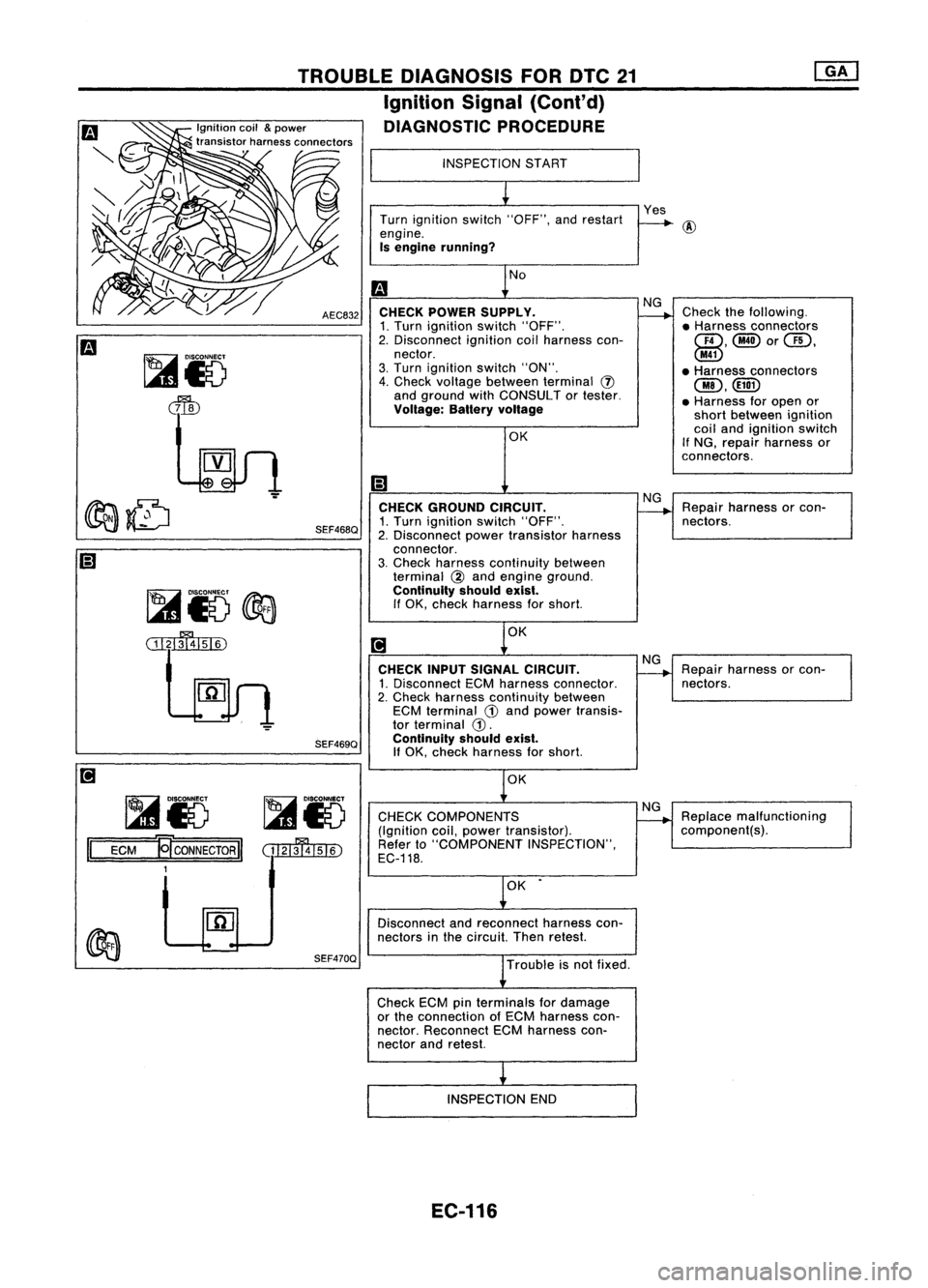
INSPECTION
START
Turn ignition switch"OFF", andrestart
engine.
Is engine running?
No
CHECK POWER SUPPLV.
1. Turn ignition switch"OFF".
2. Disconnect ignitioncoilharness con-
nector.
3. Turn ignition switch"ON".
4. Check voltage between terminal
(J)
and ground withCONSULT ortester.
Voltage: Balteryvoltage
CHECK INPUTSIGNAL CIRCUIT.
1. Disconnect ECMharness connector.
2. Check harness continuity between
ECM terminal
G)
and power transis-
tor terminal
G).
Continuity shouldexist.
If
OK, check harness forshort.
AEC832
SEF468Q
TROUBLE
DIAGNOSIS FORDTC21
Ignition Signal(Cont'd)
DIAGNOSTIC PROCEDURE
SEF469Q
~15
@3
ill~
~85 ~85
II
ECM
~CONNECTORII
(tI2IffllsI6)
1 OK
CHECK COMPONENTS
(Ignition coil,power transistor).
Refer to"COMPONENT INSPECTION",
EC-118. NG
Replace malfunctioning
component(s).
OK •
Disconnect andreconnect harnesscon-
nectors inthe circuit. Thenretest.
SEF470Q
Troubleisnot fixed.
Check ECMpinterminals fordamage
or the connection ofECM harness con-
nector. Reconnect ECMharness con-
nector andretest.
INSPECTION END
EC-116