Page 639 of 1701
LOCATIONOFELECTRICAL UNITS
Passenger Compartment
LHD MODELS
Rearwindow defogger timer
(With daytime lightsystem)
Warning buzzerunit
Combination flasherunit
Junction boxNO.2 (Joint connectors)
Stop lamp switch
Mirror defogger relay
(With daytime lightsystem)
Sun roofrelay (Without powerwindow)
Power window relay(With power window)
Front foglamp relay
SMJ (Main harness-
engine roomharness) NATS
IMMU (Gasoline engine)
Door locktimer
ABS control unit
Front wiper amplifier
SMJ (Main harness-
front doorharness)
SMJ (Main harness-
front doorharness)
Rear wiper amplifier
Daytime lightunit
Circuit breaker
Fuel pump relay
(Gasoline engine)
Fuse block
(JIB)
Ignition relay
Blower relay
Accessory relay Air
bag diagnosis sensorunit
(With dualairbag system)
ECM (ECCS control module) (Gasoline engine)
ECM (Engine controlmodule) (Dieselengine)
ECCS relay(Gasoline engine)
EL-267 HEL
150
•
Page 755 of 1701
ADJUSTING VALUE BASIC
SERVICE PROCEDURE @K]
Idle Speed/Ignition TiminglldleMixtureRatio
Adjustment (Cont'd)
Engine GA14DE,GA16DE
GA16DEGA16DE
models (ForEurope andIsrael) GA15DE
(ForAustralia) (Except
forEurope and
Israel, andAustralia)
MfT
(Without AfT
AfT AfTAfT
Transaxle (With
day-
daytime (in
"N"
MfT(in
"N" MfT(in"N" MfT(in
"N"
time light
lightsys- position)
position) position)position)
system) tem)
Base idle
speed 625::t50 625::t50 725::t50 580::t50
700::t50 625::t50
725::t50600::1:50 750::t50
(rpm)
Idle speed
800::t50 700::t50 800::t50630::t50 750::t50 675::t50 800::t50 650::1:50 800::t
50
(rpm)
Ignition timing 10::t2
10::t2
10::t2 6::t26::t2 8::t28::t210::t2 10::t2
CBTDC)
EC-36
Page 783 of 1701

TROUBLEDIAGNOSIS -General Description
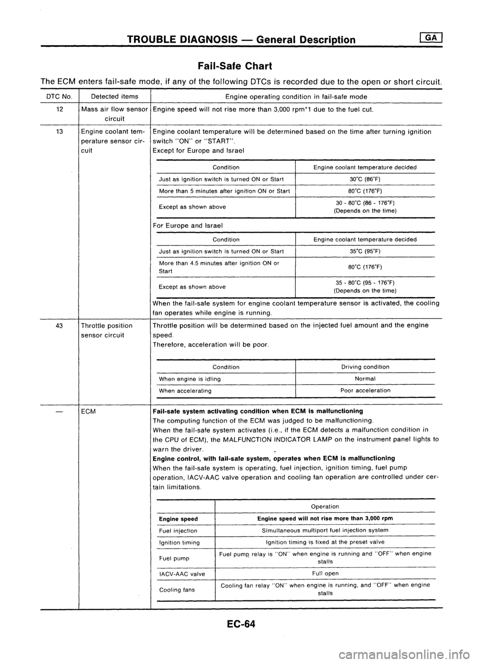
Fail-Safe Chart
The ECM enters fail-safe mode,ifany ofthe following DTCsisrecorded duetothe open orshort circuit.
DTC No. Detected
items
Engineoperating conditioninfail-safe mode
12 Massairflow sensor
Enginespeedwillnotrise more than3,000 rpm*1 duetothe fuel cut.
circuit
13 Engine
coolant tem-
Engine coolant temperature willbedetermined basedonthe time after turning ignition
perature sensorcir-switch "ON"or"START".
cuit ExceptforEurope andIsrael
Condition Enginecoolant temperature decided
Just asignition switchisturned ONorStart 30'C(B6'F)
More than5minutes afterignition ONorStart BO'G
(176'F)
Except asshown above 30
-BO'C (B6-176'F)
(Depends onthe time)
For Europe andIsrael
Condition Enginecoolant temperature decided
Just asignition switchisturned ONorStart 35'C
(95'F)
More than4.5minutes afterignition ONor
BO'G(176'F)
Start
Except asshown above 35
-BO'C (95-176'F)
(Depends onthe time)
When thefail-safe systemforengine coolant temperature sensorisactivated, thecooling
fan operates whileengine isrunning.
43 Throttle position Throttle
position willbedetermined basedonthe injected fuelamount andtheengine
sensor circuit speed.
Therefore, acceleration willbepoor.
Condition Driving
condition
When engine isidling Normal
When accelerating Poor
acceleration
-
ECM
Fail-safe
systemactivating conditionwhenECMismalfunctioning
The computing functionofthe ECM wasjudged tobe malfunctioning.
When thefail-safe systemactivates (i.e.,ifthe ECM detects amalfunction conditionin
the CPU ofECM), theMALFUNCTION INDICATORLAMPonthe instrument panellightsto
warn thedriver.
Engine control, withfail-safe system,operates whenECMismalfunctioning
When thefail-safe systemisoperating, fuelinjection, ignitiontiming,fuelpump
operation, IACV-AACvalveoperation andcooling fanoperation arecontrolled undercer-
tain limitations.
Operation
Engine speed Engine
speed
will
notrise more than3,000 rpm
Fuel injection Simultaneous
multipartfuelinjection system
Ignition timing Ignition
timingisfixed atthe preset valve
Fuel pump Fuel
pump' relayis"ON" when engine isrunning and"OFF" whenengine
stalls
IACV-AAG valve Full
open
Cooling fans Cooling
fanrelay "ON" whenengine isrunning, and"OFF" whenengine
stalls
EC-64
Page 875 of 1701

TROUBLEDIAGNOSIS FORNON-DETECTABLE ITEMS
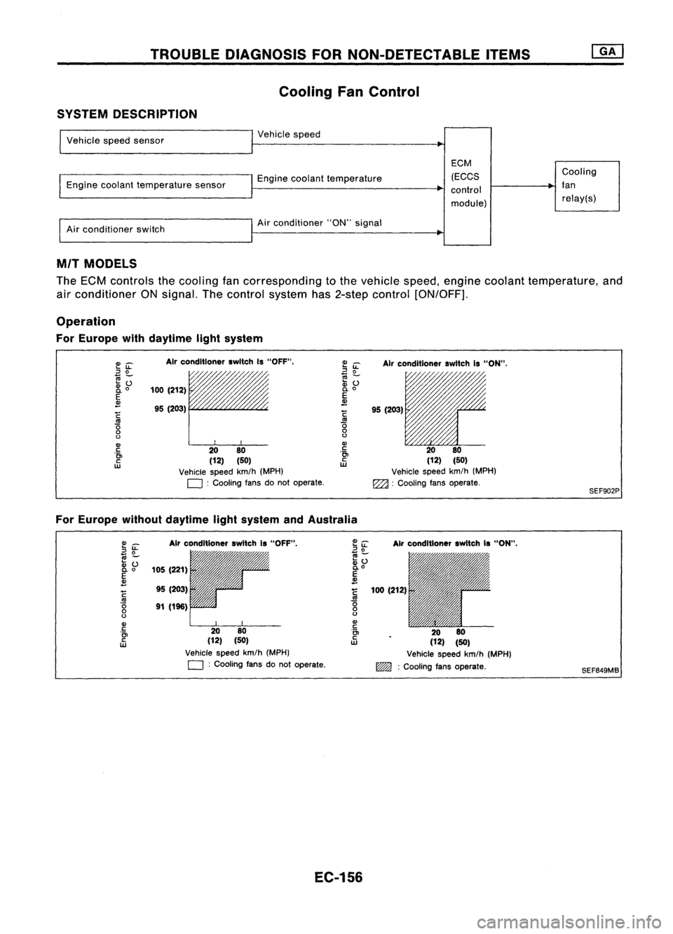
Cooling FanControl
SYSTEM DESCRIPTION
Vehicle speedsensor
Engine coolant temperature sensor
Air conditioner switch Vehicle
speed
Engine coolant temperature
Air conditioner "ON"signal
EGM
(EGGS
control
module) Gooling
fan relay(s)
MIT MODELS
The ECM controls thecooling fancorresponding tothe vehicle speed,engine coolant temperature, and
air conditioner ONsignal. Thecontrol system has2-step control [ON/OFF].
Operation
For Europe withdaytime lightsystem
E~
::J
0
~Z;
2i
o
E
~
~
'0
o
o
Gl
c
'0>
c
w
Air
conditioner switchIs"OFF".
/,
100 (212)
95 (203)
rr
20 80
(12) (50)
Vehicle speedkm/h(MPH)
D :
Cooling fansdonot operate.
~
iL
Airconditioner switchIs"ON".
~ ~ 11'l1/1~~~
:v
() /'/"
0.
0
E
~
!
95(203)
.~ 2080
ill
(12)(50)
Vehicle speedkm/h(MPH)
EZ2l :
Cooling fansoperate.
SEF902P
For Europe withoutdaytime lightsystem andAustralia
Gl_
2~
.,
-
:v ()
0.0
E
~
~
'0
o
o
Gl
c
'0>
c
w
Air
conditioner switchIs"OFF",
105 (221)
95 (203)
91 (196)
2080
(12) (50)
Vehicle speedkm/h(MPH)
D :
Cooling fansdonot operate.
Air
conditioner switchIs"ON",
100 (212)
2080
(12) (50)
Vehicle speedkm/h(MPH)
~ :Cooling fansoperate.
SEF649MB
EC-156
Page 876 of 1701

TROUBLEDIAGNOSIS FORNON-DETECTABLE ITEMS
Cooling FanControl (Cont'd)
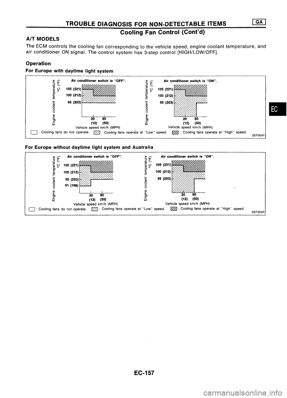
AIT MODELS
The ECM controls thecooling fancorresponding tothevehicle speed,engine coolant temperature, and
air conditioner ONsignal. Thecontrol system has3-step control
[HIGH/LOW/OFF],
Operation
For Europe withdaytime lightsystem
•
SEF904P
Air
conditioner switchIs"ON".
105 (221)
100 (212)
95 (203)
Air
conditioner switchIs"OFF".
95 (203)
105
(221)
100 (212)
C
'0
o
()
Q)
c
'0>
c
UJ
~
iL
::J
0
e;-
~o
E
~
C
'0
o
()
Q)
~ 00
i~
00
(12) (50)
tD
(12)(50)
Vehicle speedkm/h(MPH) Vehiclespeedkm/h(MPH)
o :
Cooling fansdonot operate. ~:Cooling fansoperate at"Low" speed. ~:Cooling fansoperate at"High" speed.
For Europe withoutdaytime lightsystem andAustralia
SEF905P
Air
conditioner switchis"ON",
105 (221)
100 (212)
95 (203)
Air
conditioner switchIs"OFF".
95 (203)
91 (196)
105
(221)
100 (212)
~
'0
o
()
Q)
c
'0>
c
UJ
~~
::J
0
(;j-
.... 0
~o
E
2
C
'0
o
()
Q)
~ 00
i~
00
(12) (50)
tD
(12)(50)
Vehicle speedkm/h(MPH) Vehiclespeedkm/h(MPH)
o :
Cooling fansdonot operate.
l22a:
Cooling fansoperate at"Low" speed. ~:Cooling fansoperate at"High" speed.
EC-157
Page 877 of 1701
TROUBLEDIAGNOSIS FORNON-DETECTABLE ITEMS
Cooling FanControl (Cont'd)
EC-COOL/F-01
BATTERY (Via
fusible link)
IGNITION
SWITCH
ON or START
10A
1251
FUSE
BLOCK
(JIB)
(E106)
30A
IT]
Refer
to
EL-POWER.
(1):
(8):
@:
@:
LHD
models
RHO models
LHD AIT models
for Europe without
daytime lightsystem
Except
@
page
GY
t:}
Nextpage
BR ~
-: Detectable line
for DTC
-: Non-detectable
line forDTC
I
ECM (ECCS
CONTROL
MODULE)
-----------CED
IQ~OI
GY
- I-
BR
-----0--<\])----------
9-I--@-------------
SR GY
I!'
'$1
COOLING
n
FAN
U
RELAY-1
lki=U~rn>
LG/R
G/B
I ..
'
--------0--<1»-------
G/B
-i9>
Next page
1$
T---
00
L~ ~(E10t) G~BG!B
1I1¥J1
I~I
rFh
m
LG/R LG/R
COOLING ~COOLING
FAN FAN
~~ M
MOTOR-1
M
MOTOR-2
"t
m:@@:@
L
0 ~
ll4JI
I
BB
LG/R~g
I------~-=
B
-I9>}
r:::!::,
'l:!::!3' _
-@>
Nex
t
Iml •..
-~@-----------
LGE
'-i-'@
LG/R LG
m
ldoll
RFRL RFRH
+
@
2 1L
5
@)
@~
W
@
GY,GY
Refer
tolast page
(Foldout page).
(E10t)
,
(E106)
HEC044
EC-158
Page 878 of 1701
TROUBLEDIAGNOSIS FORNON-DETECTABLE ITEMS
Cooling FanControl (Cont'd)
EC-COOL/F-02
•
LHD
A/T
models
for Europe without
daytime lightsystem
Except@
Detectable line
for DTC
Non-detectable line forDTC
-:
@:
-:
@:
-
Preceding {:::
~L: ..
page _
<&SR~
SRGYLG/S
COOLING
II!II~II:!rI
~~~AY-2 ~~
rn:@ ~~
I4J
I
GCB_
-j--T=====I,
(E10f)
n
l!F
Ii
GISG/Y GISG/Y
CHID
LG
IcP~-t~1 :~~~ IcP~-~$I :~~~
I
t
GISG/Y GISG/Y
rt=n
m rmm
LG
La
HiCOOLING
La
HiCOOLING
(M49)
II:II
(+)(+)FAN (+)(+)FAN
@
6 MOTOR-1MOTOR-2
Hi
La
(E303):
/LA'
Hi
L~
/i'"A'..
LG H(-)~H (~~: ~
~ ~ ~~
LG/B B LG/BB
IYJr --1$1
(E3Ot)
iCiJr-i$1
(E302)
~
LG/B S LG/BB
.!_! -
I~
----0------0-'.
BB
-!- -!-
~ (E51)
lmf
2
57
rn
3 6 BR
~
@
@Z)(E303) (E304)
\mJ
GY,GY ,GY ,GY
Refer
tolast page
(Foldout page).
(El0t)
,
HEC045
EC-159
Page 887 of 1701
Terminals
Speed
(EB)
(8)
Cooling fan Low
G)
@
motor-1 High
@
@
Cooling fan Low
G)
@
motor-2 High
@
@
SEF500QA
TROUBLE
DIAGNOSIS FORNON-DETECTABLE ITEMS
@]
Cooling FanControl (Cant'd)
~ IDISCD~
AfTmodels forAustralia andLHD AfTmodels forEurope with-
~ c'J
outdaytime lightsystem
1. Disconnect coolingfanmotor harness connectors.
2. Supply cooling fanmotor terminals withbattery voltage and
check operation.
Cooling fanmotor should operate.
If NG, replace coolingfanmotor.
EC-168