Page 488 of 1701
INTERIORLAMP
Illumination/Wiring Diagram-ILL -
EL-ILL-01
Refer toEL-PDWER.
:
RHOmodels
@: LHDmodels without
daytime lightsystem
@):
Except@
@: LHDmodels withdaytime
light system
@:
ForEurope andIsrael
@:
Except
@
*1'" @R/B.@R/Y.
<])RIL
LIGHTING
SWITCH
~:@
75A
W
W
LE
R
LIGHTING
SWITCH
~:@)
DAYTIME
LIGHT
UNIT
I
BATTERY
I
•
~
::.
1361
BIR
I
DL
O~------
I.-
BIR~ Next page
•
BIR
rr=m
o
L
BIR RIL
rmwfnJ
TAIL TAIL/L
FUSE SW
TAILIL
OUTPUT
~
RIB
I._-:~)I __
.IO~O-
*1
II@>
Next page
r------------------------~
~
~GY
L ~
HEL053
EL-116
Page 489 of 1701
INTERIORLAMP
Illumination/Wiring Diagram-ILL -(Cont'd)
EL-ILL-02
IN.81 IN.81
*2. RIG
I
t
I ~
0- -(C:-
RIG
~TO EL-ILL-05
o
EI
FUSE
BLOCK
(JIB)
@
(E106)
,
C
Next page
Preced
ing
{<&
~f!
page ~
~ BIR
B/R~
I~I BIR
CHID
RIG
I!I,
FRONT
FOG
LAMP
SWITCH (ILLUMINA nON)
~([@:@
B
JOINT
E Next page CONNECTOR-1
~
FRONT
FOG LAMP
SWITCH
([@:
@)
EI
To
EL-F
IFOG
.OR/B
To
EL-F/FOG. OR
:
LHOmode Is
:
RHOmodels
@:
LHOmodels without
daytime lightsystem
@:
Models withdaytime
light system
@:
ForEurope andIsrae 1
@:
Except
@
if! ...
RIB.
@
R/Y.
RIL
*2'"
~(fITQ)
rnJm] B
CillIIITIIITIII
~
~ BR
Refer
tolast page
(Foldout page).
•
HEL054
EL-117
Page 524 of 1701

WARNINGLAMPSANDBUZZER
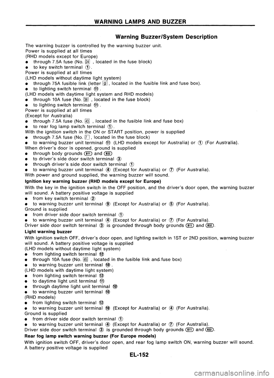
Warning Buzzer/System Description
The warning buzzeriscontrolled bythe warning buzzerunit.
Power issupplied atall times
(RHD models exceptforEurope)
• through 7.5Afuse (No.
[fA],
located inthe fuse block)
• tokey switch terminal
CD.
Power issupplied atall times
(LHD models withoutdaytime lightsystem)
• through 75Afusible link(letter
[.9J,
located inthe fusible linkand fuse box).
• tolighting switchterminal
@.
(LHD models withdaytime lightsystem andRHD models)
• through 10Afuse (No.
~J,
located inthe fuse block)
• tolighting switchterminal
@.
Power issupplied atall times
(Except forAustralia)
• through 7.5Afuse (No.~,located inthe fusible linkand fuse box)
• torear foglamp switch terminal
CD.
With theignition switchinthe ONorSTART position, powerissupplied
• through 7.5Afuse (No.
11J,
located inthe fuse block)
• towarning buzzerunitterminal
@
(LHD models exceptforAustralia) or
CD
(For Australia).
When driver's doorisopened, groundissupplied
• through bodygrounds
@
and
@
• todriver's sidedoor switch terminal
@
• through driver'ssidedoor switch terminal
G)
• towarning buzzerunitterminal
@
(Except forAustralia) or
(J)
(For Australia).
With power andground supplied, thewarning buzzerwillsound.
Ignition keywarning buzzer(RHOmodels exceptforEurope)
With thekey inthe ignition switchinthe OFF position, andthedriver's dooropen, thewarning buzzer
will sound. Abattery positive voltageissupplied
• from keyswitch terminal
CID
• towarning buzzerunitterminal
CID
(Except forAustralia) or
@)
(For Australia).
Ground issupplied
• from driver sidedoor switch terminal
G)
• towarning buzzerunitterminal
@
(Except forAustralia) or
(J)
(For Australia).
Driver sidedoor switch terminal
@
isgrounded throughbodygrounds
@
and
@.
Light warning buzzer
With ignition switchOFF,driver's dooropen, andlighting switchin1ST or2ND position, warningbuzzer
will sound. Abattery positive voltageissupplied
(LHD models withoutdaytime lightsystem)
• from lighting switchterminal
@
• through 10Afuse (No.
@ID,
located inthe fusible linkand. fuse box)
• towarning buzzerunitterminal
@>.
(LHD models withdaytime lightsystem)
• from lighting switchterminal
@
• todaytime lightunitterminal
@
• through daytime lightunitterminal
@>
• towarning buzzerunitterminal
@>
(RHD models)
• from lighting switchterminal
@
• towarning buzzerunitterminal
@>
(Except forAustralia) or
@
(For Australia).
Ground issupplied
• from driver sidedoor switch terminal
G)
• towarning buzzerunitterminal
@
(Except forAustralia) or
(J)
(For Australia).
Driver sidedoor switch terminal
@
isgrounded throughbodygrounds
(!ill
and
@.
Rear foglamp switch warning buzzer(ForEurope models)
With ignition switchOFF,driver's dooropen, andrear foglamp switch ON,warning buzzerwillsound.
A battery positive voltageissupplied
EL-152
Page 526 of 1701
WARNINGLAMPSANDBUZZER
Warning Buzzer/Wiring Diagram-BUZZER -
LHD MODELS
EL-BUZZER-01
DOOR
SWITCH
DRIVER'S
SIDE
(]ID
OPEN
Refer
to
EL-POWER.
CLOSED
IJ:i=n
B
•
f.
B B
~ ~
@ll)@
FUSE
BLOCK
(JIB)
~
m
IN~41
@:
Withdaytime lightsystem
G1@:WithoutdaytimelightsYstem
*1".@B/R @W
,
G *2...
@
RIL @W/R
•
~ *3".@R/B @R/Y
1I1DI •
IGN WARNING
SW BUZZER
RR FOG DOORUNIT
SW SW(DR)
@
lbjdJ ~
PU/R R
[ttl ']'t4IJUNCTION
BOX NO.2
(JOINT
CONNECTORS)
~------1I~41
PU/R
t
~@)
m
REAR
[jJ
(]V
IND FOG R
LAMP ~
SWITCH II1II
~
OFF
7.5A
1431
B/R
rm
TAIL/L FUSE
I!JjJJ
*2
I
O~ DL W/R
[iJt~:1
R/Y
t
I_-.I~o
tt
RIB
Ii1'on
TAILIL
OUTPUT
RIL
will
TAILIL
SW
\bj::tl
B
rn~
I
JOINT
CONNECTOR-3
I
lU ....,
DAYTIME
=jF
I
LIGHT B
UNIT BB
@ ~~
I..-.--
---J~~
I
BATTERY
I
•
~-17-5A-~'
10.
m
1361
W B/R P
!
I.-",
1$1
~~1)
*1 P
will
L
LIGHTING
SWITCH
~
~~
~BR
IIITIillIIITIIT
@
~BR
~~@)
56j8191OU12 W
r1TmCW
TIT'
B
Refer
tolast page
(Foldout page).
(BID ~
•
~ (106)
•
~~
~GY
HEL083
EL-154
Page 602 of 1701

REARWINDOW DEFOGGER ANDDOOR MIRROR DEFOGGER
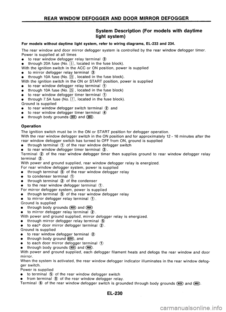
System Description (Formodels withdaytime
light system)
For models withoutdaytime lightsystem, refertowiring diagrams, EL-233and234.
The rear window anddoor mirror defogger systemiscontrolled bythe rear window defogger timer.
Power issupplied atall times
• torear window defogger relayterminal
@
• through 20Afuse (No.[[],located inthe fuse block).
With theignition switchinthe ACC orON position, powerissupplied
• tomirror defogger relayterminal
@
• through 10Afuse (No.
InJ,
located inthe fuse block).
With theignition switchinthe ONorSTART position, powerissupplied
• torear window defogger relayterminal
CD
• through 10Afuse (No.
[2ID,
located inthe fuse block)
• torear window defogger timerterminal
CD
• through 7.5Afuse(No.[[],located inthe fuse block).
Ground issupplied
• torear window defogger switchterminal
@
and
• torear window defogger timerterminal
@
• through bodygrounds
@
and
@ID.
Operation
The ignition switchmustbeinthe ONorSTART position fordefogger operation.
With therear window defogger switchinthe ONposition andforapproximately 12-16 minutes afterthe
rear window defogger switchhasturned toOFF from ON,ground issupplied
• through terminal
CD
ofthe rear window defogger switch
• torear window defogger timerterminal
@.
Terminal
@
ofthe rear window defogger timerthensupplies groundtorear window defogger relay
terminal
@.
With power andground supplied, rearwindow defogger relayisenergized.
For rear window defogger system,powerissupplied
• through terminal
CID
ofthe rear window defogger relay
• tocondenser terminal
CD
• through terminal
@
ofthe condenser
• tothe rear window defogger terminal
CD.
For mirror defogger system,powerissupplied
• through terminal
CID
ofthe rear window defogger relay
• tomirror defogger relayterminal
CD.
Ground issupplied
• through bodygrounds
@
and
@ID
• tomirror defogger relayterminal
@.
With power andground supplied, mirrordefogger relayisenergized.
• through mirrordefogger relayterminal
CID
• toeac
r
doormirror defogger terminal
@.
Ground issupplied
• torear window defogger terminal
@
• through bodyground
and
• toeach doormirror defogger terminal
CD
• through bodygrounds
@
and
@ID.
With power andground supplied, eachdefogger filamentheatsanddefogs therear window anddoor
mirror.
When thesystem isactivated, therear window defogger indicatorilluminates inthe rear window defog-
ger switch.
Power issupplied
• toterminal
CID
ofthe rear window defogger switch
• from terminal
CID
ofthe rear window defogger relay.
Terminal
@
ofthe rear window defogger switchisgrounded throughbodygrounds
@
and
@.
EL-230
Page 603 of 1701
REARWINDOW DEFOGGER ANDDOOR MIRROR DEFOGGER
Wiring Diagram -DEF -
LHD MODELS WITHDAYTIME LIGHTSYSTEM
EL-DEF-01
Gasoline engine
Diesel engine
@:
@) :
Refer
toEL-POWER.
FUSE
BLOCK
(JIB)
CM15)
~06)
CE120)
20A
W
II
P•2
1
LIB
! ~
~¥~~OW
I
J
12~r~~GER
~ 1!:iJI~:@
G/R L/R~:
@
JOINT
~ ~ ~ CONNECTOR-2
I~~-----~ ~
G/R
L/R ~
1. L/R-[J
Et
L/R - L/R~} Nextpage
!di
L/R - L/R~
~ ~~
1-------
Lf
I
RIG
+
ToEL-ILL
G/B
L/R
RIG
B
n1il ~
n=tD (!J1
~f} ~¥~~OW INDILL ~¥~~OW JOINT
SW DEFOGGER DEFOGGERCONNECTOR-3
TIMER OFF SWITCH~
GND ~ ~
11111
11211 9F
~ ~t
B.
B BBB
I--ll-l-l 11
(M"2B)
G/R
~
OUT PUT
G
IftlJ
IGN
+
~:@
2 1
5
~:@
L
r1ITr1l~
ITITITJ
GY
ITIIIII:illTIIi
~
~BR
Refer
tolast page •
(Foldout page).
F.ffi1
tm::l
W
fffffi~
rn:mrn
W
HEL136
EL-231
Page 605 of 1701
REARWINDOW DEFOGGER ANDDOOR MIRROR DEFOGGER
Wiring Diagram -DEF -(Conl'd)
LHD MODELS WITHOUT DAYTIMELIGHTSYSTEM
EL-DEF-03
•
Refer
tolast page
(Foldout page).
~
L/R~
... B
~1
B
@QD
=
r:
j
:'I~
CONDENSER
REAR
WINDOW
DEFOGGER
lbjJJ~
B
!-
~
-
~:
Sedanmodels
~ :Hatchback models
~----------------~
: F.=1
@
,(0104) B~ :
'WB B@B
I
I I
L ~
filllaID
@g]
W
-----------------
RIG.
ToEL-ILL
r1TTI1l@
IT1IITI
GY
~~g~K
RefertoEL-POWER.
(JIB)
~
i
L/R JOINT
. CONNECTOR-2
[¥
1 ~
REAR
~~~gg~ER ~L/R
---I
SWITCH L/R
~ II
J
II
I"TI'A\
~ ~ ~~
~ ~ L/R ICIJI
(]I)
L/R B
B
I
t
LIR
Ll:!
~!
s
I
L/R
B
IcIJlm~~
rn~
I
L/R~
JOINT
L~
CONNECTOR-3 L/R~
II UI ...B~
~ B~
=
I
m~
CONOENsrn
REAR
WINDOW
tt
ll
DEFOGGER
lbjJJ~
B
-!- -!-
1
~ (868)
ffiill1~
~ W
I1III1IIIIIIIII ~
~BR r-------------.,
: F.=1~
B~:
I
W
B
@
B
I
I I
L
j
HEL138
EL-233
Page 638 of 1701
LOCATIONOFELECTRICAL UNITS
Engine Compartment
Front wiper motor (LHDmodels)
Fusible linkand relay box ASS
relay boxand actuator (RHOmodels)
Front wiper motor (RHOmodels)
Glow relay(CDengine models)
Fusible linkand fuse box
Cooling fan
relay-2 Rear
foglamp relay
• Cooling fanrelay-3 (SRengine
AT models andCDengine)
Rear window defogger relay
(GA engine withdaytime lightsystem)
EL-266 Fusible
linkand fuse box
Fusible linkand relay box
Rear window defogger relay
(CD engine withdaytime lightsystem)
HEL149