1995 NISSAN ALMERA N15 lights
[x] Cancel search: lightsPage 989 of 1701
TROUBLEDIAGNOSIS -General Description
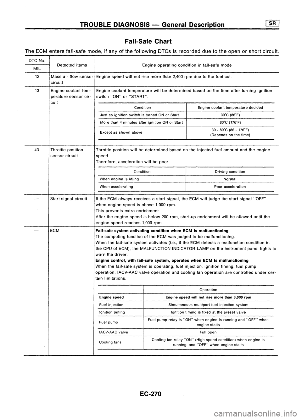
Fail-Safe Chart
The ECM enters fail-safe mode,ifany ofthe following DTCsisrecorded duetothe open orshort circuit.
DTC No.
Detected items Engineoperating conditioninfail-safe mode
MIL
12 Massairflow sensor Enginespeedwillnotrise more than2,400 rpmduetothe fuel cut.
circuit
13 Enginecoolant tem-Engine coolant temperature willbedetermined basedonthe time after turning ignition
perature sensorcir-switch "ON"or"START".
cuit ConditionEnginecoolant temperature decided
Just asignition switchisturned ONorStart 30'C(86'F)
More than4minutes afterignition ONorStart 80'C(176'F)
Except asshown above 30
-80'C (86-176'F)
(Depends onthe time)
43 Throttle position
Throttleposition willbedetermined basedonthe injected fuelamount andtheengine
sensor circuit
speed.
Therefore, acceleration willbepoor.
Condition Drivingcondition
When engine i$idling
Normal
When accelerating Pooracceleration
-
Start
signal circuit
If
the ECM always receives astart signal, theECM willjudge thestart signal "OFF"
when engine speedisabove 1,000rpm.
This prevents extraenrichment.
After theengine speedisbelow 200rpm, start-up enrichment willbeallowed untilthe
engine speedreaches 1,000rpm.
-
ECM
Fail-safesystemactivating conditionwhenECMismalfunctioning
The computing functionofthe ECM wasjudged tobe malfunctioning.
When thefail-safe systemactivates (i.e.,ifthe ECM detects amalfunction conditionin
the CPU ofECM), theMALFUNCTION INDICATORLAMPonthe instrument panellightsto
warn thedriver.
Engine control, withfail-safe system,operates whenECMismalfunctioning
When thefail-safe systemisoperating, fuelinjection, ignitiontiming,fuelpump
operation, IACV-AACvalveoperation andcooling fanoperation arecontrolled undercer-
tain limitations.
Operation
Engine speed Enginespeedwillnotrise more than3,000 rpm
Fuel injection
Simultaneousmultiportfuelinjection system
Ignition timing Ignitiontimingisfixed atthe preset valve
Fuel pump Fuel
pump relayis"ON" whenengine isrunning and"OFF" when
engine stalls
IACV-AAC valve
Fullopen
Cooling fans Cooling
fanrelay "ON" (Highspeed condition) whenengine is
running, and"OFF" whenengine stalls
EC-270
Page 1136 of 1701
SERVICEDATAANDSPECIFICATIONS (SOS)
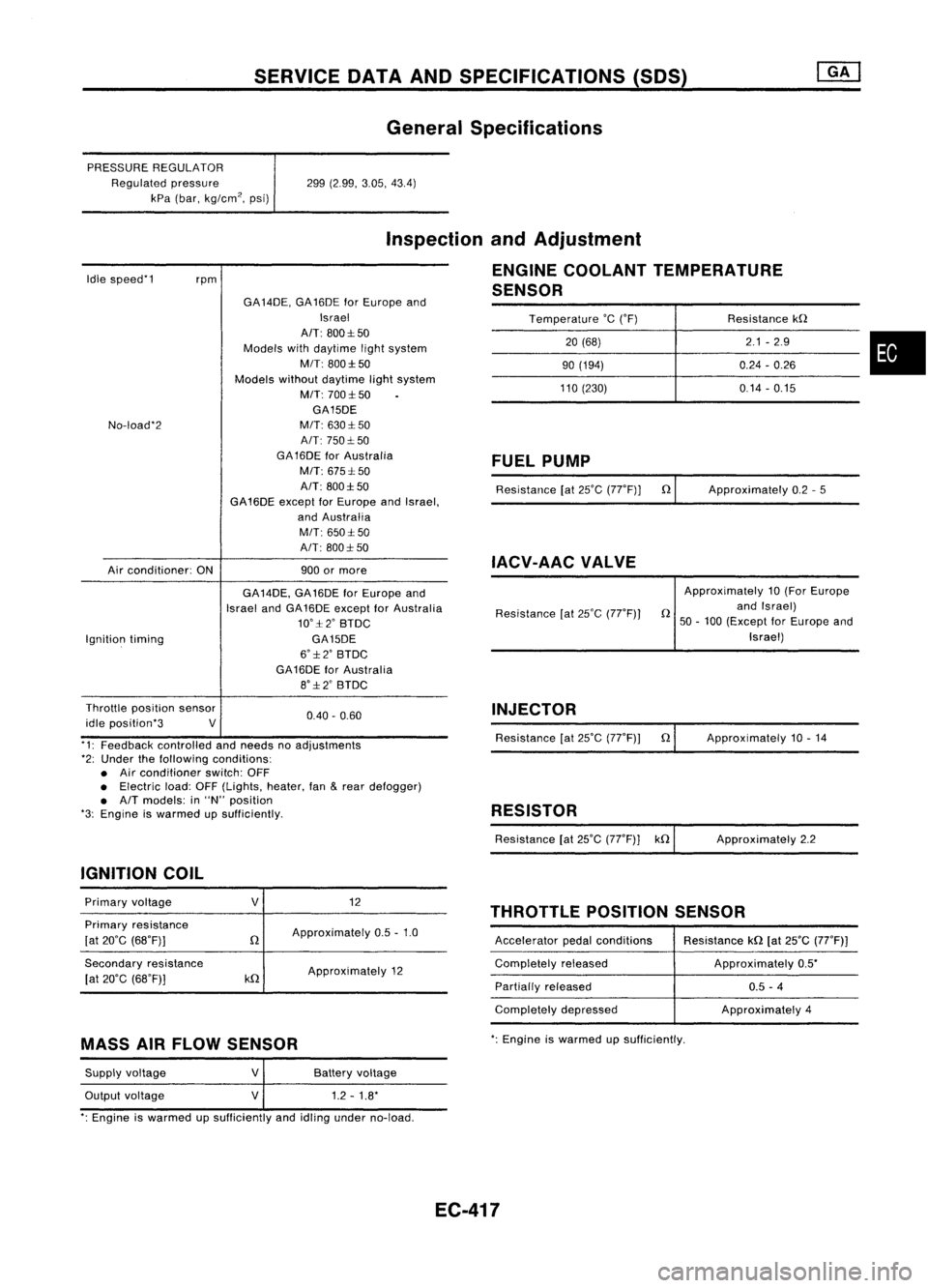
General Specifications
PRESSURE REGULATOR
Regulated pressure
kPa (bar, kg/cm
2,
psi) 299
(2.99, 3.05,43.4)
Idle speed'1
rpm
Inspection
andAdjustment
ENGINE COOLANT TEMPERATURE
SENSOR
Temperature
'c
('F) Resistancekn
20 (68) 2.1
-2.9
•
90
(194) 0.24-0.26
110 (230) 0.14-0.15
No-load'2
Air conditioner: ONGA
14DE, GA16DE forEurope and
Israel
AIT: 800:1:50
Models withdaytime lightsystem
MIT: 800:1:50
Models withoutdaytime lightsystem
M/T: 700:1:50
GA15DE
M/T: 630:1: 50
A/T: 750:1: 50
GA 16DE forAustralia
M/T: 675:1: 50
A/T: 800:1:50
GA16DE exceptforEurope andIsrael,
and Australia
M/T: 650:1:50
A/T: 800:1: 50
900 ormore
FUEL
PUMP
Resistance [at25'C (77'F)] n
IACV-AAC VALVE
Approximately
0.2-5
Ignition timing GA
14DE, GA16DE forEurope and
Israel andGA16DE except forAustralia
10':1:2' BTDC
GA15DE
6':1:2' BTDC
GA16DE forAustralia
8':1:2' BTDC Resistance
[at25'C (77'F)) Approximately
10(For Europe
n andIsrael)
50 -100 (Except forEurope and
Israel)
0.40. 0.60
Throttle
position sensor
idle position'3 V
'1: Feedback controlled andneeds noadjustments
'2: Under thefollowing conditions:
• Air conditioner switch:OFF
• Electric load:OFF(Lights, heater,fan
&
rear defogger)
• A/T models: in"N" position
'3: Engine iswarmed upSUfficiently.
IGNITION COIL INJECTOR
Resistance [at25'C (77'F)) n
RESISTOR
Resistance [at25'C (77'F)] kn Approximately
10.14
Approximately 2.2
THROTTLE POSITIONSENSOR
Primary
voltage
Primary resistance
[at 20'C (68'F)]
Secondary resistance
[at 20'C (68'F)]
V
n
kn
12
Approximately 0.5-1.0
Approximately 12 Accelerator
pedalconditions
Completely released
Partially released
Completely depressed Resistance
kn[at25'C (77'F))
Approximately 0.5'
0.5 -4
Approximately 4
MASS AIRFLOW SENSOR
':
Engine iswarmed upsufficiently.
Supply voltage
Output voltage
V
V
Battery
voltage
1.2 -1.8'
': Engine iswarmed upSUfficiently andidling under no-load.
EC-417
Page 1137 of 1701
SERVICEDATAANDSPECIFICATIONS (SOS)
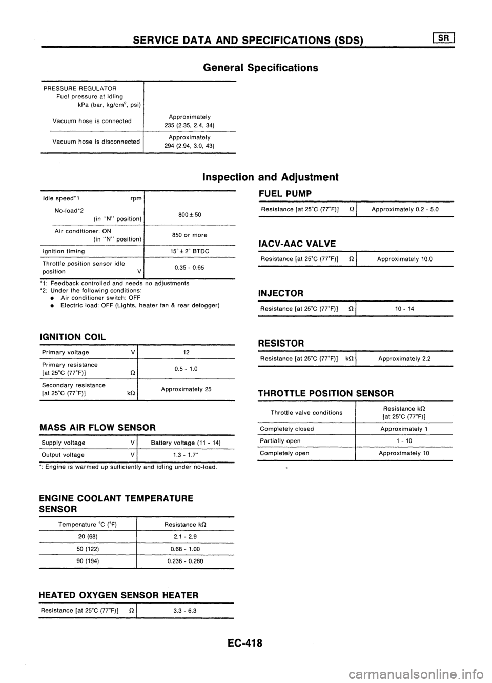
General Specifications
PRESSURE REGULATOR
Fuel pressure atidling
kPa (bar, kg/cm
2,
psi)
Vacuum hoseisconnected
Vacuum hoseisdisconnected Approximately
235 (2.35. 2.4.34)
Approxi mately
294 (2.94, 3.0,43)
Idle speed'1
No-load'2 rpm
(in "N" position) 800:1:50
Inspection
andAdjustment
FUEL PUMP
Resistance [at25'C (77'F)] n
Approximately 0.2-5.0
Air conditioner: ON
(in "N" position)
Ignition timing
Throttle position sensoridle
position V850
ormore
IACV-AACVALVE
15':1:2' BTDC
Resistance[at25'C (77'F)] n
0.35 -0.65 Approximately
10.0
'1: Feedback controlled andneeds noadjustments
'2: Under thefollowing conditions:
• Air conditioner switch:OFF
• Electric load:OFF(Lights, heaterfan
&
rear defogger)
IGNITION COIL INJECTOR
Resistance [at25'C (77'F)) n'
1_0_-_1_4 _
RESISTOR
Primary voltage
Primary resistance
[at 25'C (77'F))
V
12
0.5 -1.0 Resistance
[at25'C (77'F)) kn ApproXimately 2.2
Secondary resistance
[at 25'C (77'F))
kn
Approximately
25
THROTTLEPOSITIONSENSOR
MASS AIRFLOW SENSOR
Supply voltage
Output voltage
V
V
Battery
voltage (11-14)
1.3 -1.7'
Throttle
valveconditions
Completely closed
Partially open
Completely open Resistance
kn
[at 25'C (77'F)]
Approximately 1
1 - 10
Approximately 10
': Engine iswarmed upsufficiently andidling under no-load.
ENGINE COOLANT TEMPERATURE
SENSOR
Temperature
'c
('F)
20 (68)
50 (122)
90 (194) Resistance
kn
2.1-2.9
0.68 -1.00
0.236 -0.260
HEATED OXYGEN SENSOR HEATER
Resistance [at25'C (77'F)] n
I
3.3-6.3
EC-418
Page 1382 of 1701
HOWTOPERFORM EFFICIENT DIAGNOSIS FORANELECTRICAL INCIDENT
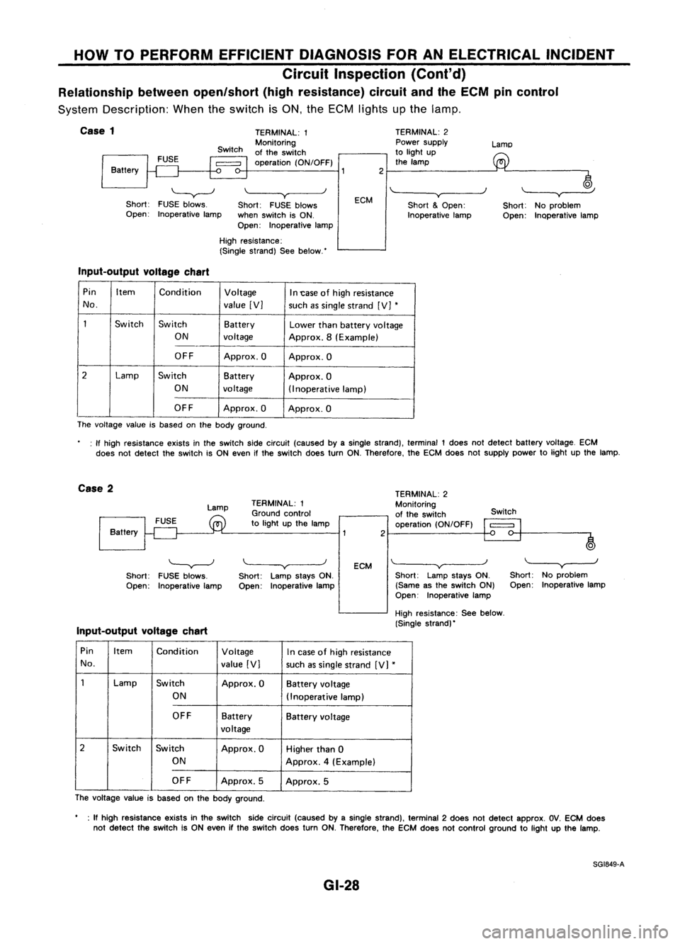
Circuit Inspection (Cont'd)
Relationship betweenopen/short (highresistance) circuitandtheECM pincontrol
System Description: Whentheswitch isON, theECM lights upthe lamp.
j
Case
1
Battery
'-----v--J
Short: FUSEblows.
Open: Inoperative lamp TERMINAL:
1
Monitoring
of the switch
operation (ON/OFF)
\~--~y
Short: FUSEblows
when switch isON.
Open: Inoperative lampECM
2
TERMINAL:
2
Power supply
to light up
the lamp
'"-----v~----)
Short
&
Open:
Inoperative lampLamo
~
Short: Noproblem
Open: Inoperative lamp
High resistance:
(Single strand) Seebelow.'
Input-output voltagechart
Pin Item
Condition Voltage
In1:ase ofhigh resistance
No. value[V]
suchassingle strand [V]
*
1
Switch
Switch Battery
Lowerthanbattery voltage
ON voltage Approx.8(Example)
OFF Approx.O Approx.O
2
Lamp
Switch Battery
Approx.O
ON voltage
(Inoperativelamp)
OFF Approx.O Approx.O
The voltage valueisbased onthe body ground.
: If high resistance existsinthe switch sidecircuit (caused byasingle strand), terminal 1does notdetect battery voltage. ECM
does notdetect theswitch isON even ifthe switch doesturnON.Therefore. theECM does notsupply powertolight upthe lamp.
Case 2
Lamp
Battery TERMINAL:
1
Ground control
to light upthe lamp
2TERMINAL:
2
Monitoring
of the switch
operation (ON/OFF) Switch
o
)
'---v---J
Short: FUSEblows.
Open: Inoperative lamp
Input-output voltagechart
\.----v
Short: LampstaysON.
Open: Inoperative lamp
ECM
\~--~v~--_.J
Short: LampstaysON.
(Same asthe switch ON)
Open: Inoperative lamp
High resistance: Seebelow.
(Single strand)'
"---y-----.J
Short: Noproblem
Open: Inoperative lamp
Pin Item Condition Voltage
Incase ofhigh resistance
No. value[V]
suchassingle strand [V]
*
1
Lamp
Switch
Approx.OBatteryvoltage
ON (Inoperat ivelamp)
OFF Battery
Batteryvoltage
voltage
2
Switch Switch Approx.OHigherthan0
ON Approx.4(Example)
OFF Approx.5
Approx.5
The voltage valueisbased onthe body ground.
• :If high resis1ance existsinthe switch sidecircuit (caused byasingle strand), terminal 2does notdetect approx. OV.ECM does
not detect theswitch isON even ifthe switch doesturnON.Therefore, theECM does notcontrol ground tolight upthe lamp.
SG1849-A
GI-28
Page 1419 of 1701
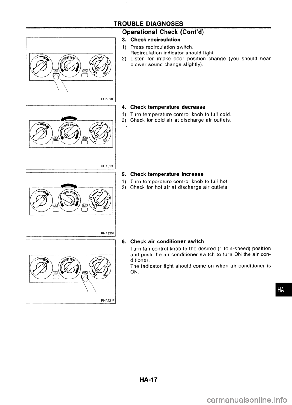
RHA318F
4.Check temperature decrease
~~ ~~~nC~ef~~~~~~ur~ cont:olknobtofull cold.
air atdischarge airoutlets.
TROUBLE
DIAGNOSES
Operational Check(Cont'd)
3. Check recirculation
1) Pre~s recirculation switch.
2) ~.eclrculati~n indicatorshouldlight
Isten forIntake doorposition ch'an
blower soundchange slightly). ge(you should hear
RHA319F
5.Check temperature increase
~~ ~~rn ~efmperatu:e controlknobtofull hot
ec orhot airatdischarge airoutlets:
RHA320F
6.Check airconditioner switch
Turn fancontrol knobtothe desired 1
a~? push theairconditioner 'th (to 4-speed) position
dltlOner.
SWI
ctoturn ONtheaircon-
The indicator lightshould com .
ON. eon when airconditioner is
•
RHA321F
HA-17
Page 1436 of 1701
TROUBLEDIAGNOSES
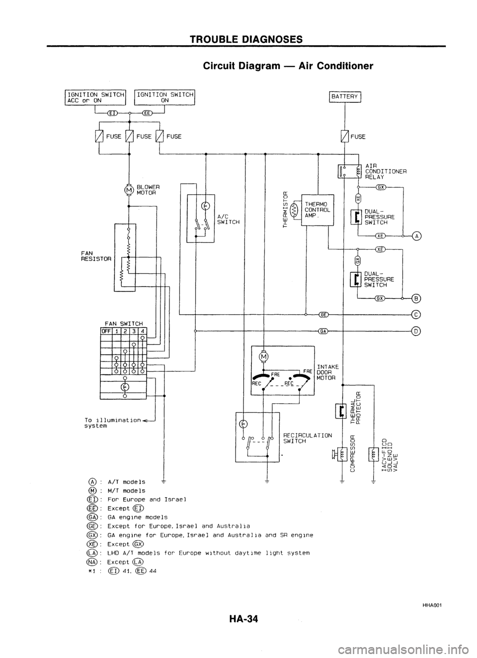
Circuit Diagram -Air Conditioner
DUAL-PRESSURE
SWITCH
AIR
CONDITIONER
RELAY
THERMO
CONTROL
AMP.
IT
o
f-
U1
H
~
IT
W
I
f-
AIC
SWITCH
M
BLOWER
MOTOR
FAN
RESISTOR
GE
C
FAN SWITCH
OFF1234
GA
D
o
uo
HH
[LO
IZW
>w>
U..J....J
404
HUJ>
IT
o
..JI-
«u
~w
IT
I-
wo
IIT
f-(L
IT
o
U1
U1
W
IT
(L
~
o
u
RECIRCULA
nON
SWITCH
1
AIT models
MIT
models
For Europe andIsrael
Except
@
GA engine models
Except
f
or Europe, Israe 1and Austra 1ia
GA eng ine
f
or Europe, Israe1and Austra 1ia and SReng Ine
Except
@
LHD
AIT
models forEurope without daytIme lightsystem
Except
@
41.
@
44
@:
@:
@:
@:
@:
@:
@:
@:
@:
*1
To
illumination
system
HHA001
HA-34
Page 1448 of 1701
TROUBLEDIAGNOSES
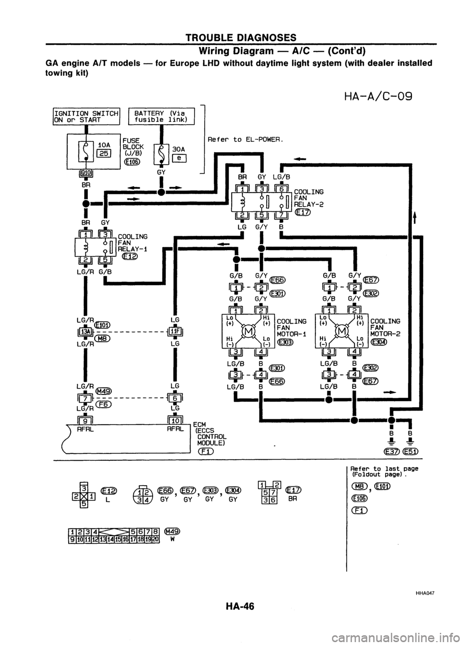
Wiring Diagram -
A/C -
(Cont'd)
GA engine AfTmodels -for Europe LHDwithout daytime lightsystem (withdealer installed
towing kit)
HA-A/C-09
BATTERY (Via
fusible link)
t
COOLING
FAN
MOTOR-2
~
•
I
GIS
G/Y
ID
$-$@g)
GIS
G/Y
mrn
La Hi
1+) 1+)
-
COOLING
FAN
MOTOR-1
Hi La~ HiLa
H H~ HH
IkjJJ ~ ~~
LG/S S
@D
LG/SS~
IrjJ~ -
$
66
IrjJ~-
i$/
6
LG/S S
@
LG/SS
ID
I-I
&-_I!__~.,
S S
~ ~
~~
SR
GYLG/S
~ ~RELAY-2
~~~rn> LG
G/Y
S
I '
-
.
i
I
T-
GIS G/Y@
IciJ~ -
t~J1@D
GIS G/Y
mm
La Hi
1+) (+)
Refer
toEL-POWER.
I
ECM
(ECCS
CONTROL
MODULE)
em
FUSE
BLOCK 30A
(JIB)
r-e-t
(El06) ~
IQ;OI
GY
BR _
1_
f-p:=_e:::::-
BR GY
1:Jt1 :lJIICOOLING
n
FAN
U
RELAY-1
IbjJJ
ILi=U
LG/R G/B
I
LG/R~ LG
~\EJQ!I ~
~M8----------~
Li~
I
LG/R~ LG
Iqp~-~~---------~qpl
LG/R
CEID
LG
m
ffiJl
2
RFRL RFRL
¥
@
2 1L
5
rffi\
@ID,
@?),
(f303), ~
t:]JY
GYGYGY GY
"2
57
@
36 SR
Refer
tolast page
(Foldout page).
CHID,
(El06)
em
@
W
HHA047
HA-46
Page 1491 of 1701
PRE-DELIVERYINSPECTIONITEMS
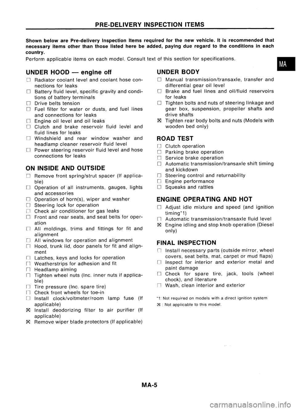
Shown belowarePre-delivery InspectionItemsrequired forthe new vehicle. Itis recommended that
necessary itemsotherthanthose listedherebeadded, payingdueregard tothe conditions ineach
country.
Perform applicable itemsoneach model. Consult textofthis section forspecifications .
UNDER HOOD-engine off
o
Radiator coolantlevelandcoolant hosecon-
nections forleaks
o
Battery fluidlevel, specific gravityandcondi-
tions ofbattery terminals
o
Drive beltstension
D
Fuel filter forwater ordusts, andfuel lines
and connections forleaks
[] Engine oillevel andoilleaks
D
Clutch andbrake reservoir fluidlevel and
fluid lines forleaks
o
Windshield andrear window washerand
headlamp cleanerreservoir fluidlevel
D
Power steering reservoir fluidlevel andhose
connections forleaks
ON INSIDE ANDOUTSIDE
D
Remove frontspring/strut spacer(Ifapplica-
ble)
D
Operation ofall instruments, gauges,lights
and accessories
o
Operation ofhorn(s), wiperandwasher
[] Steering lockforoperation
[] Check airconditioner forgas leaks
o
Front andrear seats, andseat belts foroper-
ation
n
All moldings, trimsandfittings forfitand
alignment
[J
Allwindows foroperation andalignment
n
Hood, trunklid,door panels forfitand align-
ment
[1
Latches, keysandlocks foroperation
rl
Weatherstrips foradhesion andfit
[l
Headlamp aiming
I~ Tighten wheelnuts(Inc. inner nutsifapplica-
ble)
IJ Tire pressure (Inc.spare tire)
Il
Check frontwheels fortoe-in
IJ Install clock/voltmeter/room lampfuse(If
applicable)
~ Install deodorizing filtertoair purifier (If
applicable)
~ Remove wiperbladeprotectors (Ifapplicable)
UNDER
BODY
o
Manual transmission/transaxle, transferand
differential gearoillevel
D
Brake andfuel lines andoil/fluid reservoirs
for leaks
D
Tighten boltsandnuts ofsteering linkageand
gear box,suspension, propellershaftsand
drive shafts
~ Tighten rearbody boltsandnuts (Models with
wooden bedonly)
ROAD TEST
D
Clutch operation
D
Parking brakeoperation
[J
Service brakeoperation
D
Automatic transmission/transaxle shifttiming
and kickdown
[] Steering controlandreturnability
o
Engine performance
D
Squeaks andrattles
ENGINE OPERATING ANDHOT
D
Adjust idlemixture andspeed (andignition
timing*1)
n
Automatic transmission/transaxle fluidlevel
~ Engine idlingandstop knob operation (Diesel
only)
FINAL INSPECTION
n
Install necessary parts(outside mirror,wheel
covers, seatbelts, mat,carpet ormud flaps)
[1
Inspect forinterior andexterior metaland
paint damage
[] Check forspare tire,jack, tools (wheel
chock), andliterature
n
Wash, cleaninterior andexterior
"1: Not required onmodels withadirect ignition system
~ :Not appiicable tothis model.
•
MA-5