Page 356 of 1701
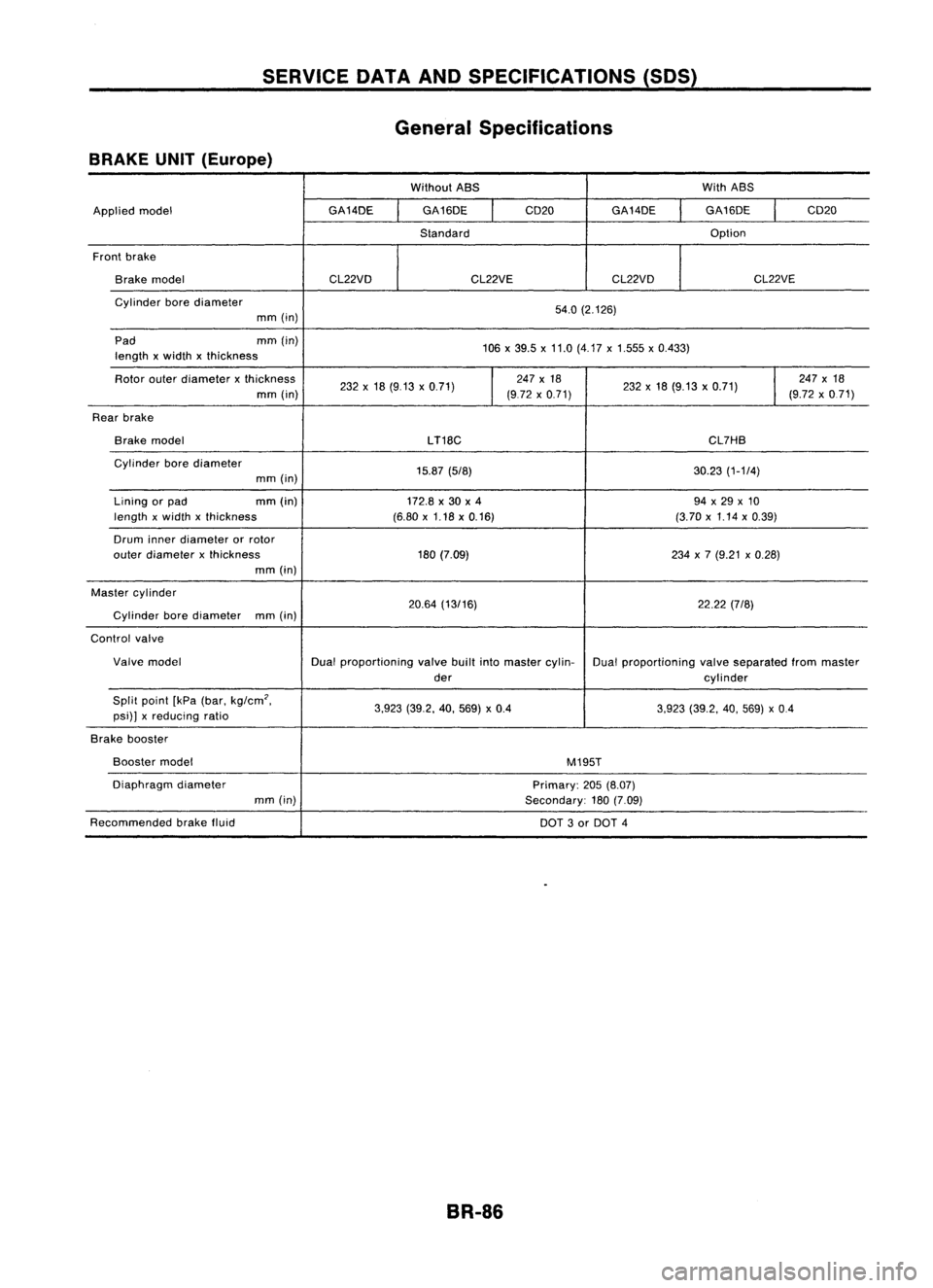
SERVICEDATAANDSPECIFICATIONS (SOS)
General Specifications
BRAKE UNIT(Europe)
WithoutABS WithABS
Applied model GA14DE
GA16DE
I
CD20
GA14DE GA16DE
I
CD20
Standard Option
Front brake
Brake model CL22VDCL22VECL22VD CL22VE
Cylinder borediameter
54.0(2.126)
mm (in)
Pad mm(in)
106x39.5 x11.0 (4.17 x1.555 x0.433)
length xwidth xthickness
Rotor outerdiameter xthickness
232x18 (9.13 x0.71)
I
247
x18
232x18 (9.13 x0.71)
I
247
x18
mm (in) (972x0.71) (9.72x0.71)
Rear brake
Brake model
LT18C CL7HB
Cylinder borediameter
15.87(5/8) 30.23(1-1/4)
mm (in)
Lining orpad mm
(in)
172.8x30 x4 94x29 x10
length xwidth xthickness (6.80x1.18 x0.16) (3.70x1.14 x0.39)
Drum innerdiameter orrotor
outer diameter xthickness 180(7.09) 234x7 (9.21 x0.28)
mm (in)
Master cylinder
20.64(13/16) 22.22(7/8)
Cylinder borediameter
mm(in)
Control valve
Valve model Dualproportioning valvebuiltintomaster cylin-
Dualproportioning valveseparated frommaster
der cylinder
Split point [kPa(bar. kg/cm
2•
3.923(39.2. 40.569) x0.4
3.923(39.2. 40.569) x0.4
psi)] xreducing ratio
Brake booster
Booster model
M195T
Diaphragm diameter
Primary:205(8.07)
mm (in)
Secondary:180(7.09)
Recommended brakefluid
DOT3or DOT 4
BR-86
Page 357 of 1701
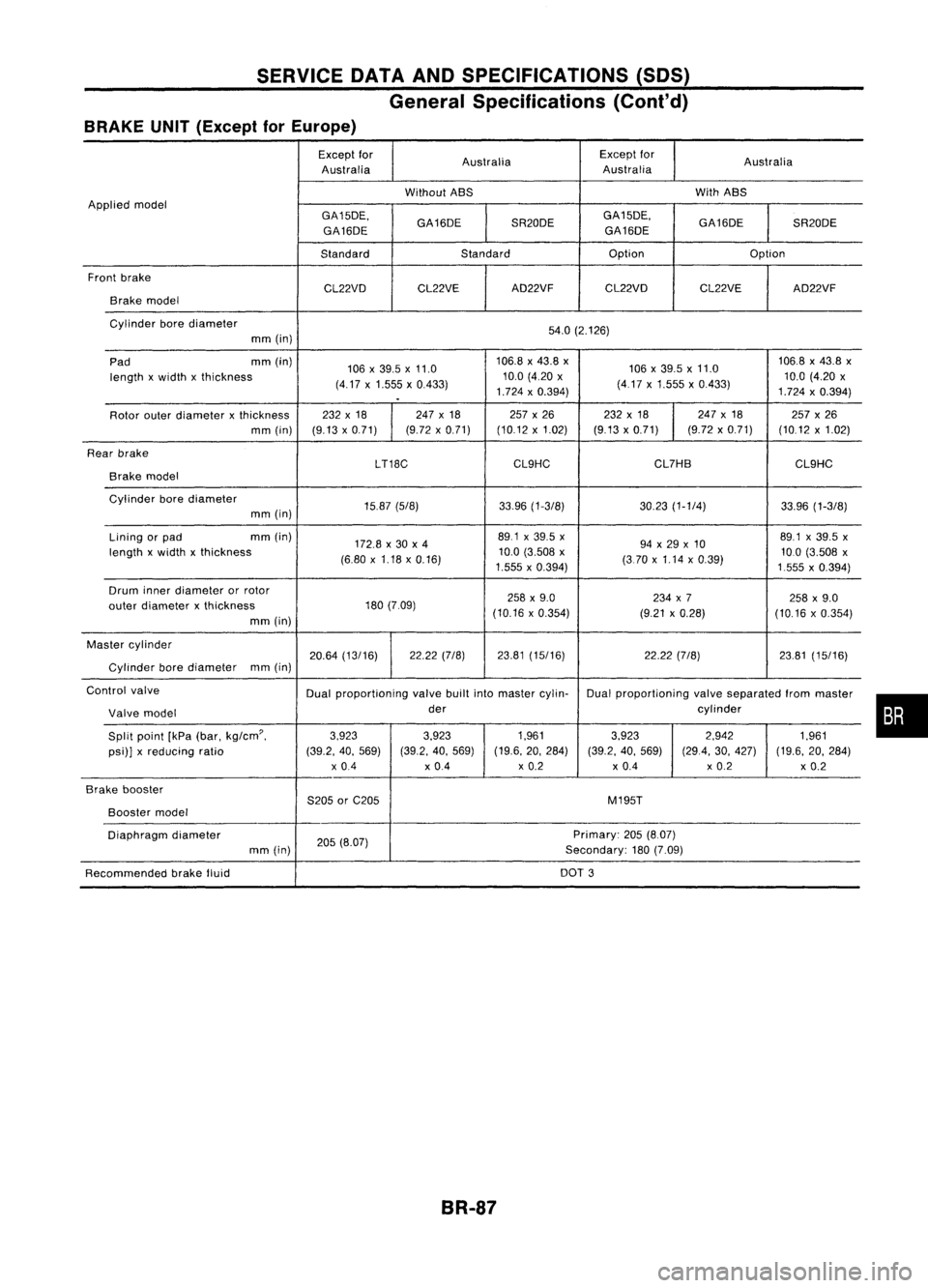
SERVICEDATAANDSPECIFICATIONS (SDS)
General Specifications (Cont'd)
BRAKE UNIT(Except forEurope)
Except for
Australia Except
for
Australia
Australia Australia
Without ABS With
ABS
Applied model
GA15DE.GA16DESR20DEGA15DE.
GA16DESR20DE
GA16DE GA16DE
Standard Standard Option
Option
Front brake
CL22VDCL22VE AD22VF
CL22VD CL22VEAD22VF
Brake model
Cylinder borediameter
54.0(2.126)
mm (in)
Pad mm
(in)
106x39.5 x11.0 106.8
x43.8 x
106x39.5x11.0 106.8
x43.8 x
length xwidth xthickness
(4.17x1.555 x0.433) 10.0
(4.20 x
(417x1.555 x0.433) 10.0
(4.20 x
.
1.724
x0.394)
1.724x0.394)
Rotor outerdiameter xthickness 232
x18 247x18 257x26 232x18 247
x18
257x26
mm (in) (9.13x0.71) (9.72
x0.71) (10.12x1.02) (9.13x0.71) (9.72x0.71) (10.12x1.02)
Rear brake
LT18CCL9HC CL7HB
CL9HC
Brake model
Cylinder borediameter
15.87(5/8) 33.96(1-3/8) 30.23(1-1/4) 33.96(1-3/8)
mm (in)
Lining orpad mm
(in)
172.8x30 x4 89.1
x39.5 x
94x29 x10 89.1
x39.5 x
length xwidth xthickness
(6.80x1.18 x0.16) 10.0
(3.508 x
(370x1.14 x0.39) 10.0
(3.508 x
1.555 x0.394)
1555x0.394)
Drum innerdiameter orrotor
258x9.0 234x7
258x9.0
outer diameter xthickness 180
(7.09)
(10.16x0.354) (9.21x0.28)
(10.16x0.354)
mm (in)
Master cylinder
20.64(13/16) 22.22
(7/8) 23.81(15/16) 22.22(7/8) 23.81(15/16)
Cylinder borediameter mm
(in)
Control valve
Dualproportioning valvebuiltintomaster cylin- Dualproportioning valveseparated frommaster
Valve model der
cylinder
Split point [kPa(bar.
kg/cm'.
3.923
3.923 1.9613.923 2.942
1.961
psi)] xreducing ratio (39.2.40.569) (39.2.40.569) (19.6.
20.284)
(39.2.40.569) (29.4.30.427) (19.6.20.284)
x 0.4 x0.4 x
0.2
x0.4 x
0.2
x0.2
Brake booster
S205orC205 M195T
Booster
model
Diaphragm diameter
205(8.07) Primary:
205(8.07)
mm (in) Secondary:180(7.09)
Recommended brakefluid DOT
3
BR-87
•
Page 360 of 1701
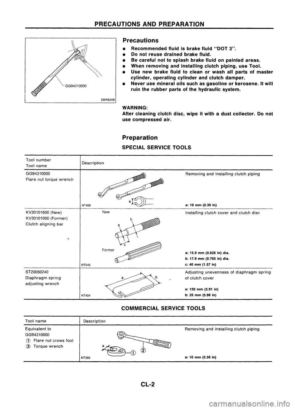
PRECAUTIONSANDPREPARATION
Precautions
• Recommended fluidisbrake fluid"DOT 3".
• Donot reuse drained brakefluid.
• Becareful nottosplash brakefluidonpainted areas.
• When removing andinstalling clutchpiping, useTool.
• Use new brake fluidtoclean orwash allparts ofmaster
cylinder, operating cylinderandclutch damper.
• Never usemineral oilssuch asgasoline orkerosene. Itwill
ruin therubber partsofthe hydraulic system.
Tool number
Tool name
SBR820B
WARNING:
After cleaning clutchdisc,wipe itwith adust collector. Donot
use compressed air.
Preparation
SPECIAL SERVICE TOOLS
Description
New
GG94310000
Flare nuttorque wrench
KV30101600 (New)
KV30101000 (Former)
Clutch aligning bar
ST20050240 Diaphragm spring
adjusting wrench
NT406
NT645
NT404
Removing
andinstalling clutchpiping
a:
10
mm
(0.39
in)
Installing clutchcoverandclutch disc:
a:
15.9
mm
(0.626 In)dia.
b: 17.9 mm(0.705 in)dia.
c: 40 mm (1.57 in)
Adjusting unevenness ofdiaphragm spring
of clutch cover
a: 150 mm (5.91 in)
b: 25
mm
(0.98
in)
Tool name
Description
COMMERCIAL
SERVICETOOLS
Equivalent to
GG9431 0000
CD
Flare nutcrows foot
@
Torque wrench
NT360
Removing
andinstalling clutchpiping
a: 10 mm (0.39 in)
CL-2
Page 363 of 1701
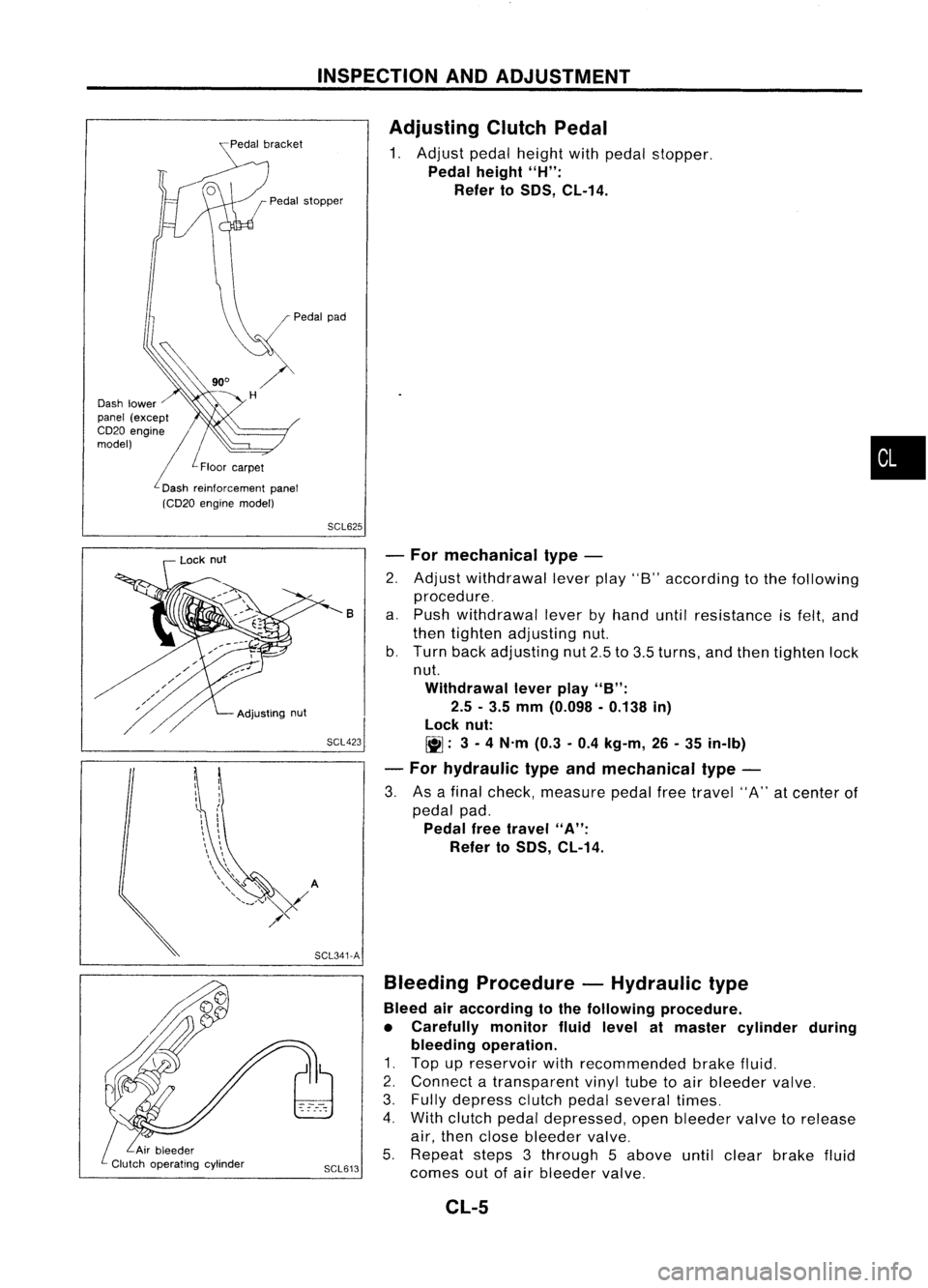
INSPECTIONANDADJUSTMENT
Pedal stopper
Dash lower
panel (except
CD20 engine //
model)
/L
Floor car-pet
L
Dash reinforcement panel
(CD20 engine model)
Adjusting
ClutchPedal
1. Adjust pedalheight withpedal stopper.
Pedal height
"H":
Refer to
50S,
CL-14.
•
SCL625
SCL423 -
For mechanical type-
2. Adjust withdrawal leverplay"8"according tothe following
procedure_
a. Push withdrawal leverbyhand untilresistance isfelt, and
then tighten adjusting nut.
b. Turn backadjusting nut2.5to3.5 turns, andthen tighten lock
nut.
Withdrawal leverplay
"B":
2.5 -3.5 mm (0.098 -0.138 in)
lock nut:
~: 3-
4 N'm (0.3-0.4 kg-m, 26-35 in-Ib)
- For hydraulic typeandmechanical type-
3. Asafinal check, measure pedalfreetravel "A"atcenter of
pedal pad.
Pedal freetravel
"A":
Refer to
50S,
CL-14.
B
Bleeding Procedure -Hydraulic type
Bleed airaccording tothe following procedure.
• Carefully monitorfluidlevel atmaster cylinder during
bleeding operation.
1. Top upreservoir withrecommended brakefluid.
2. Connect atransparent vinyltubetoair bleeder valve.
3. Fully depress clutchpedalseveral times.
4. With clutch pedaldepressed, openbleeder valvetorelease
air, then close bleeder valve.
5. Repeat steps3through 5above untilclear brake fluid
SCL613
comesoutofair bleeder valve.
SCL341-A
Adjusting
nut
Lock
nut
CL-5
Page 364 of 1701
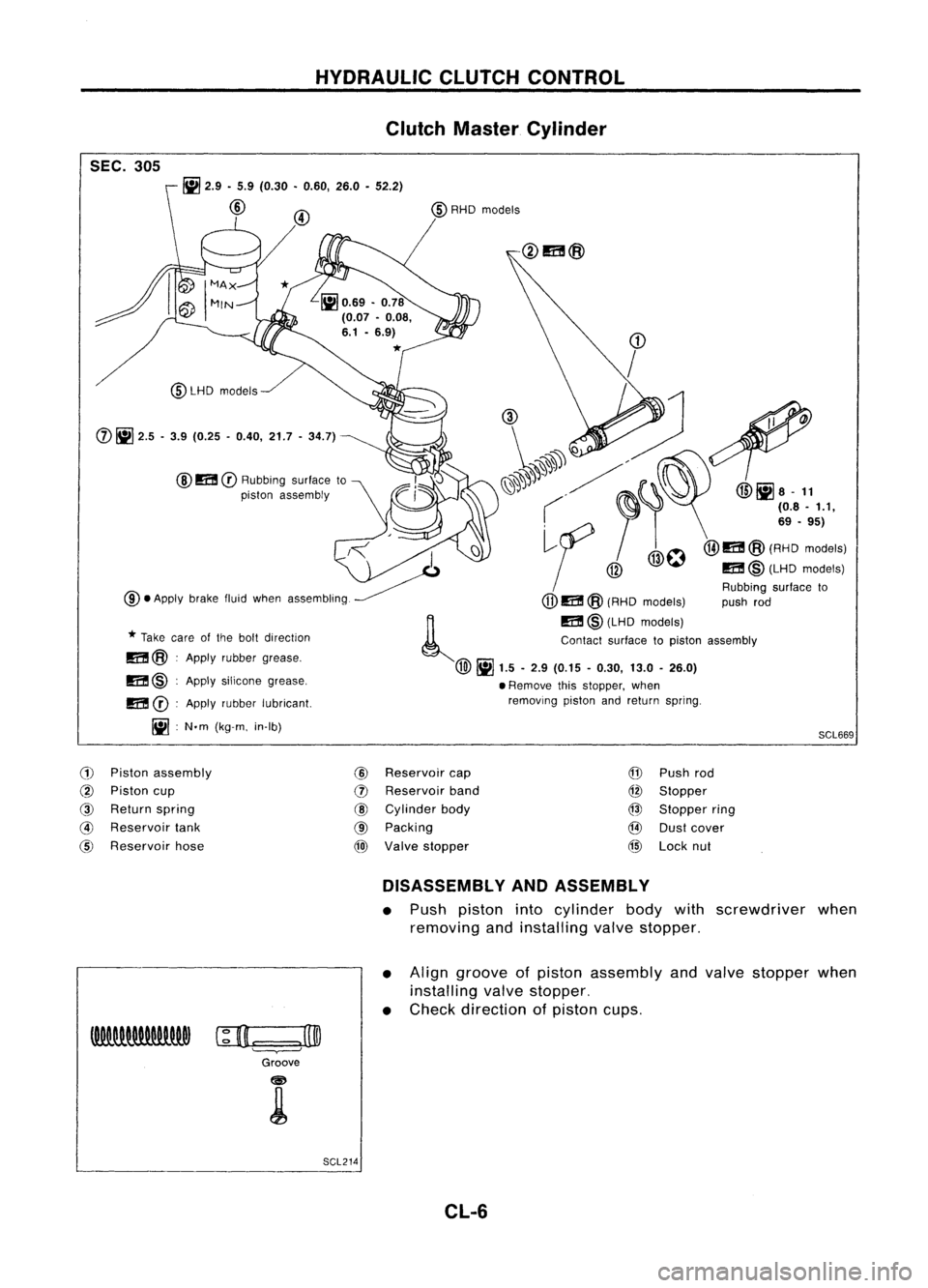
HYDRAULICCLUTCHCONTROL
Clutch Master Cylinder
SEC. 305
SCL669
~
2.9 •5.9 (0.30 •0.60, 26.0•52.2)
@
@
m
CD
Rubbing surfaceto
piston assembly
@LHD
models
m @:Apply silicone grease,
m
CD:
Apply rubber lubricant.
Iil :
N.m (kg-m. in-Ib)
CD
/
(1), ~
1'.
~'. ~". @liJa-
11
( ~I'
(08.'.1,
,<
I
~f
/@O@I1I!@(A':o'::"'1
~ @
m@(LHDmodels)
Rubbing surfaceto
@.
Apply brakefluidwhen assembling.
(jJ)
m @(RHD models) pushrod
~ m@(LHD models)
*
Take careofthe bolt direction Contactsurfacetopiston assembly
m@ :Apply rubber grease.
@~
1.5-2.9 (0.15 -0.30, 13.0-26.0)
• Remove thisstopper, when
removing pistonandreturn spring.
(j)
~
2.5 -3.9 (0.25 -0.40, 21.7-34.7)
(1)
Piston assembly
@
Reservoir
cap
@
Piston cup
(])
Reservoir
band
@
Return spring
@
Cylinder body
@
Reservoir
tank
@
Packing
@
Reservoir hose
@)
Valve stopper
@
Push rod
@
Stopper
@
Stopper ring
@
Dustcover
@
Lock nut
DISASSEMBLY ANDASSEMBLY
• Push piston intocylinder bodywithscrewdriver when
removing andinstalling valvestopper.
• Align groove ofpiston assembly andvalve stopper when
installing valvestopper.
• Check direction ofpiston cups.
c;D.=:
=.J3@
Groove
SCL214 CL-6
Page 392 of 1701

GROUNDDISTRIBUTION
GROUND CONNECTTO CONN.
NO. CELLCORD
E37/E51 AIRBAG DIAGNOSIS SENSORUNIT(Single
E108 RS-SRS
air bag system)
BRAKE FLUIDLEVEL SWITCH E2EL-WARN
CLEARANCE LAMPLH E50EL-TAILIL
CLEARANCE LAMPRH E33EL-TAILIL
COOLING FANMOTOR-1 (1-modetype) E45 EC-COOLIFHA-A/C
COOLING FANMOTOR-1 (2-modetype-GA
E66 EC-COOLIF
HA-A/C
engine forEurope)
COOLING FANMOTOR-1 (2-modetype-ex-
E46 EC-COOLIF
HA-A/C
eept GAengine forEurope)
COOLING FANMOTOR-2 (1-modetype)
E39 EC-COOLIFHA-A/C
-
COOLING FANMOTOR-2 (2-modetype-GA
E67 EC-COOLiF
HA-A/C
engine forEurope)
COOLING FANMOTOR-2 (2-modetype-ex-
E40 EC-COOLIFHA-A/C
eept GAengine forEurope)
COOLING FANRELAY-1 E12
EC-COOLIFHA-A/C
COOLING FANRELAY-2 E17
EC-COOLIFHA-A/C
COOLING FANRELAY-3 E18EC-COOLIF
HA-A/C
DAYTIME LIGHTUNIT E119EL-DTRL
FRONT FOGLAMP LH E52EL-F/FOG
FRONT FOGLAMP RH
E36EL-F/FOG
FRONT TURNSIGNAL LAMPLH E53EC-TURN
FRONT TURNSIGNAL LAMPRH E32EC-TURN
FRONT WIPERANDWASHER SWITCH E113
EL-WIPER
FUEL FILTER SWITCH
E5EL-WARN
HEADLAMP AIMINGMOTOR UNITLH E48
EL-AIM
HEADLAMP AIMINGMOTOR UNITRH E35 EL-AIM
HEADLAMP LH E49EL-H/LAMP
EL-DTRL
HEADLAMP RH E34EL-H/LAMP
EL-DTRL
HEADLAMP WIPERMOTOR LH E44
EL-HLC
HEADLAMP WIPERMOTOR RH E41EL-HLC
IACV-FICD SOLENOID VALVE(LHDmodels
.
E65 EC-A/CCUTHA-A/C
with CD20 engine)
INHIBITOR SWITCH E222EC-PNP/SWAT-A
IT EL-START
NEUTRAL POSITION SWITCH E220EC-PNP/SW
POWER STEERING OILPRESSURE SWITCH
E3 EC-PST/SW
(RHO models withgasoline engine)
REAR FOGLAMP RELAY E20EL-R/FOG
REAR WIPER ANDWASHER SWITCH E112EL-WIP/R
REAR WIPER RELAY E15EL-WIP/R
SIDE TURN SIGNAL LAMP(Driver side) E1 EL-TURN
WASHER FLUIDLEVEL SWITCH E30EL-WARN
EL-20
Page 510 of 1701
WARNINGLAMPSANDBUZZER
Warning Lamps/Schematic
>-
[[
W
f-
f-
CD
w
(f)
:J
l.L
UG
NATS
SECURITY
INDICATOR
NATSIMMU
ABS ABS
CONTROL
UNIT
OIL OILPRESSURE SWITCH
FUEL
FUELTANKGAUGE UNIT
WASHER
WASHERFLUIDLEVELSWITCH
DOOR
FRONTDOORSWITCH
(Driver's side)
FRONT DOORSWITCH
(Passenger side)
REAR ODOR SWITCH LH
ALTERNATOR PARKING
BRAKESWITCH
FUEL FILTER SWITCH
=
BRAKE
FLUIDLEVEL SWITCH
REAR
ODORSWITCH RH
=
WARNING
BUZZER
UNIT
=
ECM (ECCS
CONTROL
MODULE)
ECM
(ENGINE
CONTROL
MODULE)
I
U
f- W
H (f)
3:f-
:J
(f)[[
l.L
Zf-
O(f)
H
f-L
HO
Z
BELT
C!JZ
HO
BRAKE
Q)
(I)
D.
rl
0
Q)
L
D
::J
0
W
E
L
C
0
ro
""-
D
Q)
(I)
(f)
rl
Q)
ro
D
D
'M
C
0
rl
ro
E
ro
L
~
Q) Q)
.....
u
C C
(I)
ro
.M
Q)
.M
ro
::J
.0
OJ
C
OJ
.M
.c
c
.M
C
rl
U
Q)
OJ
Q)
ro
L
+'
C
L
0
ro
Q) Q) Q)
.....
""-
I
C C
(I)
GLOW
.M
rl
.
M
::J
.....
L
rl
Q)
rl
D.
0
0
(I)
0
Q)
0
(I)
Q)
(I)
L
u
D
ro
.M
ro
0
x
I
C!J
0
C!J
l.L
W
lD
MALFUNCTION
@@~@@@
INDICATOR
AIRBAG
AIRBAG
DIAGNOSIS
SENSOR
UNIT
HEL082
EL-138
Page 513 of 1701
WARNINGLAMPSANDBUZZER
Warning Lamps/Wiring Diagram-WARN -
(Cont'd)
EL-WARN-03
~: Gasoline engine
~: Diesel engine
COMBINATIONMETER~~
•
Refer
tolast page
(Foldout page).
CHID
(E10
1)
(M19)
FILTER
~~
IIDID:IID
B
~~
tml
GY
BRAKE
....
_-
HIGH
ITIillJIIIIIIII ~
~BR
4=U
~
llWJ
Y
IB
ORILY
IR
Y
IR
~20 JUN~TION
I
~2
m
JOINT
~ BOXNO.2
r
Y
IB
~O (JOINT
CD
~ONNECTOR
CONNECTORS) ~
I
2..a
I
2
~@
Y/B
CBID
ORIL Y/R
I~I
@g)
I$~-- -CEl0l)- -- --
~$~ ----- --- -- ----
~ufJl
Y
IB
Y
IB
ORIL Y
IR
I
II~~~
Y/B Y/R~ Y/R@Z)
m1 I~II~I
'=r ~ '=rCE2Q1)
PARKING Y
IR
Y
IR
BRAKE •_ _.
SWITCH
~O~
~ BRAKE
I
FLUID FUEL
LOW LEVEL HIGHFILTER Y/R
~~~~CH LOW~-- ~~~~~H
@)
rn11:"1
II 2 II II2 II ALTERNATOR
T T
E
@@@)
f---t, ~
B B B
..... ..... -l
(E205)
Preceding
B
page
F.=I~
L.!J
B
....
_-
RELEASED
~-------------------------------~
L ~
Ii\Clli
tg)
GY
@
GY
r-----------.,
I I
I
,.hh
(E206) ~(E233)
I
Ilh,@
GY~
1
I I
L. -'
HEL073
EL-141