Page 17 of 1701

Fluidleakage TROUBLE
DIAGNOSES
Preliminary Check(PriortoRoad Testing)
AIT FLUID CHECK
Fluid leakage check
1. Clean areasuspected ofleaking, -for example, mating
surface ofconverter housingandtransmission case.
2. Start engine, applyfootbrake, placeselector leverin"0"
position andwait afew minutes.
3. Stop engine.
4. Check forfresh leakage.
SAT288G
Fluidcondition check
Fluid levelcheck -Refer toMA section (CHASSIS AND
BODY MAINTENANCE).
Fluid
color
Oark orblack withburned odor
Milky pink
Varnished fluid,lighttodark brown
and tacky Suspected
problem
Wear offrictional material
Water contamination
- Road water entering through
filler tubeorbreather
Oxidation
- Over orunder filling
- Overheating
•
Road Testing
Perform roadtests using "Symptom" chart.Refertopage
AT-20.
"P"
POSITION
1. Place selector leverin"P" position andstart engine. Stop
engine andrepeat theprocedure inall positions, including
neutral position.
2. Stop vehicle onaslight upgrade andplace selector leverin
"P" position. Releaseparkingbraketomake surevehicle
remains locked.
"R"
POSITION
1. Manually moveselector leverfrom"P"to"R", andnote
shift quality.
2. Drive vehicle inreverse longenough todetect slippage or
other abnormalities.
"N"
POSITION
1. Manually moveselector leverfrom"R"and"0"to"N" and
note shift quality.
2. Release parkingbrakewithselector leverin"N" position.
Lightly depress accelerator pedaltomake surevehicle
does notmove. (When vehicle isnew orsoon afterclutches
have been replaced, vehiclemaymove slightly. Thisisnot
a problem.)
AT-17
Page 24 of 1701
TROUBLEDIAGNOSES
Stall Tasting
STALL TESTPROCEDURE
1. Check
AIT
and engine fluidlevels. Ifnecessary, addfluid.
2. Drive vehicle forabout 10minutes untilengine oiland ATF
reach operating temperature.
ATF operating temperature:
50 -80
0
e (122-176°F)
SAT6478
3.Set parking brakeandblock wheels.
4. Install atachometer whereitcan beseen bydriver during
test.
SAT513G 5.
~ ~ID
•
~c;>
SAT7678
Start
engine, applyfootbrake, andplace selector leverin
"0"
position.
6. Accelerate towide-open throttlegradually whileapplying
foot brake.
7. Quickly notetheengine stallrevolution andimmediately
release throttle.
• During test,never holdthrottle wide-open formore than5
seconds. Stall revolution .standard:
Refer toSDS, AT-166.
SAT514G
8.Move selector leverto"N" position.
9. Cool offATF.
• Run engine atidle foratleast oneminute.
10. Repeat steps5through 9with selector leverin"2", "1"and
"R
n
positions.
SAT7718 AT-24
Page 26 of 1701
TROUBLEDIAGNOSES
Pressure Testing
• Location ofpressure testport.
• Always replace pressure plugsasthey areself-sealing
bolts.
Test portfor
line pressure governor
pressure
SAT565D
LINEPRESSURE TESTPROCEDURE
1. Check AfTand engine fluidlevels. Ifnecessary, addfluid.
2. Drive vehicle forabout 10minutes untilengine oiland ATF
reach operating temperature.
ATF operating temperature:
50 -80°C (122-176°F)
SAT647B
3.Install pressure gaugetoline pressure port.
4. Set parking brakeandblock wheels.
Continue todepress brakepedalfullywhile performing line
pressure testatstall speed.
SAT513G
5.Start engine andmeasure linepressure atidle and stall
speed. Line pressure:
Refer toSOS, AT-166.
JUDGEMENT OFLINE PRESSURE TEST
• Ifline pressure doesnotrise, firstcheck tomake surethat
throttle wireisconnected properly.
1) When linepressure whileidling
is
low atall positions ("D",
"2", "1", "R"and"P"), theproblem maybedue to:
SAT494G •
Wear oninterior ofoil pump
AT-26
Page 27 of 1701

'-)
(
~)o
Front
SAT498GTROUBLE
DIAGNOSES
Pressure Testing(Cont'd)
• Oilleakage ator around oilpump, control valvebody, trans-
mission caseorgovernor
• Sticking pressure regulator valve
• Sticking pressure modifiervalve
2) When linepressure whileidling islow ataparticular
position, checkthefollowing.
• Ifoil leaks ator around low
&
reverse brakecircuit, line
pressure becomes lowin"R" position. Butline pressure is
normal in"P", "D", "2"or"1" position.
3) When linepressure ishigh while idling, pressure regulator
valve mayhave stuck.
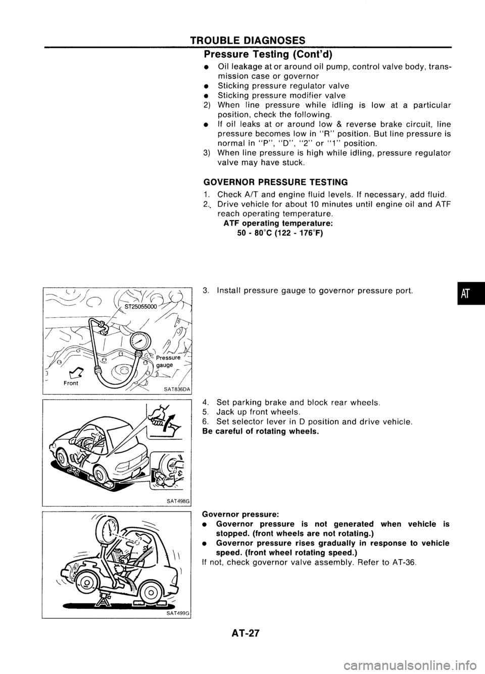
GOVERNOR PRESSURETESTING
1. Check
AIT
and engine fluidlevels. Ifnecessary, addfluid.
2 .. Drive vehicle forabout 10minutes untilengine oiland ATF
reach operating temperature.
ATF operating temperature:
50 -80°C (122-176°F)
3. Install pressure gaugetogovernor pressureport.
4. Set parking brakeandblock rearwheels.
5. Jack upfront wheels.
6. Set selector leverinDposition anddrive vehicle.
Be careful ofrotating wheels.
•
Governor pressure:
• Governor pressureisnot generated whenvehicle is
stopped. (frontwheels arenotrotating.)
• Governor pressurerisesgradually inresponse tovehicle
speed. (frontwheel rotating speed.)
If not, check governor valveassembly. RefertoAT-36.
AT-27
Page 41 of 1701
Boltlength
'T'
mm (in)
55 (2.17)
50 (1.97)
65 (2.56)
25 (0.98)
40 (1.57)
Tightening
torque
N'm (kg-m, ft-Ib)
70 -79 (7.1 -8.1,51 -59)
70 -79 (7.1 -8.1, 51-59)
70 -79 (7.1 -8.1,51 -59)
30 -40 (3.1 -4.1, 22-30)
30 -40 (3.1 -4.1, 22-30)
CD
@
@
@
@
Bolt
No.
• Reinstall anypart removed.
• Adjust throttle wireandcontrol cable.Referto"ON-VEHI-
CLE SERVICE", AT-33,35.
•. Check inhibitor switch.Referto"Electrical Components
Inspection", AT-3D.
• Refill transaxle withATFandcheck fluidlevel, AT-17.
• Move selector leverthrough allpositions tobe sure that
transaxle operatescorrectly. Withparking brakeapplied,
idle engine. Moreselector leverthrough "N"to"D", to"2",
to "1" and "R". Aslight shock should befelt through the
hand gripping theselector eachtimethetransaxle is
shifted. •
• Perform roadtest-Refer to"ROAD TESTING", AT-17.
i
REMOVAL
ANDINSTAllATION
Installation (Cont'd)
SR engine models
SAT638A
SAT558DA
AIT
toengine
@
Engine to
AIT
AT-41
Page 108 of 1701
REPAIRFOR
COMPONENT PARTS
Low
&
Reverse Brake
SAT943HA
Dish
plate
Drive
plate
Retaining
plate
*
Driven plate
Retaining plate
Driven plate
Drive
plate
* :
Select
~: Applyx~~per thickness.
SEC.
315
For the numb
refer tothe b:~O~ clutch sheets (dri
cross-section
veplates anddI
,
rven plates),
DISASSEMBL Y
1. Check operat'
a. Apply co Ionoflow
&
r
b. Check tmpressed airtoo,el vherse brake
c If
0
see that
I
ole oft .
. retaining platdretaining plateransmission ca
• D-rin .eoes n
t
moves
t
se.
• Oil gmight bedama
0
contact snap
.0
snap ring.
seal might
be
ged. ring,
• FluId might bdamaged
e leak' .
Ing past piston h
c eck ball
2. Stand trans .,
3. Remove sn~l1IS~lOn case.
4. Remov .p nng.
d' ednve plate
Ish plates fromts,~riven plate
ransmlssio s,
n case. retaining
platesand
AT-108
Page 271 of 1701

BRAKESYSTEM
SECTION
CONTENTS BR
PRECAUTIONS ANDPREPARATION
3
Precautions 3
Special Service Tools 4
Commercial ServiceTools 4
CHECK ANDADJUSTMENT 5
Checking BrakeFluidLevel 5
Checking BrakeLine 5
Changing BrakeFluid 5
AIR
BLEEDING 6
Bleeding Procedure 6
BRAKE HYDRAULIC LINE 7
Removal 8
Inspection 8
Installation 8
CONTROL VALVE 9
Proportioning Valve 9
BRAKE PEDALANDBRACKET 11
Removal andInstallation 11
Inspection 11
Adjustment 11
MASTER CYLINDER 12
Removal 12
Disassembly 12
Inspection 13
Assembly 13
Installation 14
BRAKE BOOSTER 15
On-vehicle Service 15
Removal 15
Inspection 16
Installation 16
VACUUM HOSE 17
Removal andInstallation 17
Inspection 17
FRONT DISCBRAKE 19
Pad Replacement.. 19
Removal 22
Disassembly 22Inspection
-Caliper 22
Inspection -Rotor 23
Assembly '".23
Installation 24
REAR DRUM BRAKE 25
Removal 25
Inspection -Wheel Cylinder 26
Wheel Cylinder Overhaul 27
Inspection -Drum 27
Inspection -Lining 27
Installation 27
REAR DISCBRAKE 29
Pad Replacement 29
~~s:~::~'~I~':::::::::::'::: ::.::::::::.::::::.::::::::::.::::::.::::::::~~ •••
Inspection -Caliper 32
Inspection -Rotor 33
Assembly 33
Installation 35
PARKING BRAKECONTROL 36
Removal andInstallation 36
Inspection 36
Adjustment ." 37
ANTI-LOCK BRAKESYSTEM 38
Purpose 38
Operation 38
ABS Hydraulic Circuit 38
System Components 39
System Description 39
Removal andInstallation .40
Wiring Diagram -ABS - .45
TROUBLE DIAGNOSES
52
Contents 52
Component PartsandHarness Connector
Location 64
SERVICE DATAANDSPECIFICATIONS (SDS)86
General Specifications 86
Inspection andAdjustment 88
Page 274 of 1701

GG94310000or
commercial equivalent
SBR820BA
For
tightening flarenut
Tool number
Tool name
PRECAUTIONS
ANDPREPARATION
Precautions (Conl'd)
BRAKE SYSTEM
• Recommended fluidisbrake fluid"DOT 3"or"DOT 4".
• Never reusedrained brakefluid.
• Donot mix different typesofbrake fluids (DOT3,DOT 4).
• Becareful nottosplash brakefluidonpainted areas;itmay
cause paintdamage. Ifbrake fluidissplashed onpainted
areas, washitaway withwater immediately.
• Toclean master cylinder parts,discbrake caliper partsor
wheel cylinder parts,useclean brake fluid.
• Never usemineral oilssuch asgasoline orkerosene. They
will ruin rubber partsofhydraulic system.
• Use flare nutwrench whenremoving andinstalling brake
tubes.
• Always torquebrakelineswhen installing.
WARNING:
• Clean brakes withavacuum dustcollector tominimize risk
of health hazard frompowder causedbyfriction.
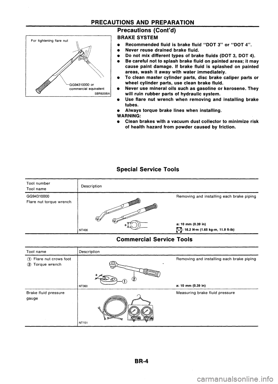
Special Service Tools
Description
GG9431 0000
Flare nuttorque wrench
NT406
Removing
andinstalling eachbrake piping
a: 10 mm (0.39 in)
~: 16.2N'm(1.65 kg-m, 11.9f1-lb)
Commercial ServiceTools
Description
Tool name
CD
Flare nutcrows foot
@ Torque wrench
Brake fluidpressure
gauge
NT360
NT151
Removing
andinstalling eachbrake piping
a: 10 mm (0.39 in)
Measuring brakefluidpressure
BR-4