Page 1500 of 1701
RECOMMENDEDLUBRICANTSANDFLUIDS
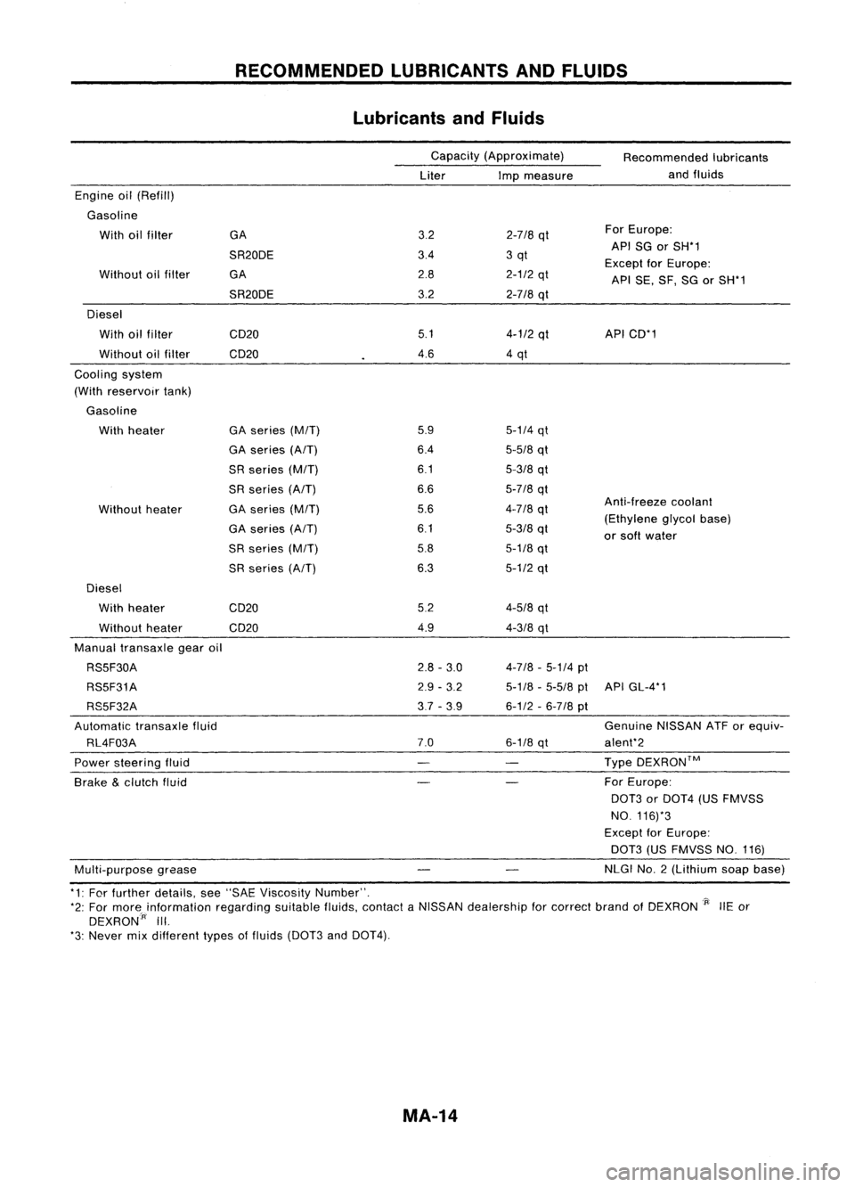
Lubricants andFluids
Capacity (Approximate)
Liter Impmeasure Recommended
lubricants
and fluids
Anti-freeze coolant
(Ethylene glycolbase)
or soft water
5-1/4
qt
5-5/8
qt
5-3/8
qt
5-7/8
qt
4-7/8
qt
5-3/8
qt
5-1/8
qt
5-1/2
qt
3.2
2-7/8
qt For
Europe:
3.4 3qt API
SGorSH*1
Except forEurope:
2.8
2-1/2
qt
APISE,SF,SGorSH*1
3.2
2-718
qt
5.1
4-1/2
qt API
CD*1
4.6 4qt
5.9
6.4
6.1
6.6
5.6
6.1
5.8
6.3
GA
SR20DE GA
SR20DE
GA series
(M/T)
GA series
(A/T)
SR series
(M/T)
SR series
(A/T)
GA series
(M/T)
GA series
(A/T)
SR series
(M/T)
SR series (AfT)
Without
heater
Without
oilfilter
Engine
oil(Refill)
Gasoline With oilfilter
Diesel With oilfilter CD20
Without oilfilter CD20
Cooling system
(With reservoir tank)
Gasoline With heater
Diesel With heater
Without heater CD20
CD20 5.2
4.9
4-5/8
qt
4-3/8
qt
Manual transaxle gearoil
RS5F30A
RS5F31A
RS5F32A
Automatic transaxlefluid
RL4F03A
Power steering fluid
Brake
&
clutch fluid
Multi-purpose grease
2.8
-3.0
2.9 -3.2
3,7 -3.9
7.0
4-7/8
-5-1/4
pt
5-1/8 -5-5/8
ptAPIGL-4*1
6-1/2 -6-7/8
pt
Genuine NISSANATForequiv-
6-1/8
qt alent*2
Type DEXRON™
For Europe:
0013
orDOT4 (USFMVSS
NO. 116)*3
Except forEurope:
DOT3 (USFMVSS NO.116)
NLGI NO.2 (Lithium soapbase)
*1: For further details, see"SAE Viscosity Number". _
*2: For morainformation regardingsuitablefluids,contact aNISSAN dealership forcorrect brandofDEXRON
'P:
liE or
DEXRON:
A
III.
*3: Never mixdifferent typesoffluids (DOT3 and
0014).
MA-14
Page 1532 of 1701
CHASSISANDBODY MAINTENANCE
Changing
MIT
Oil
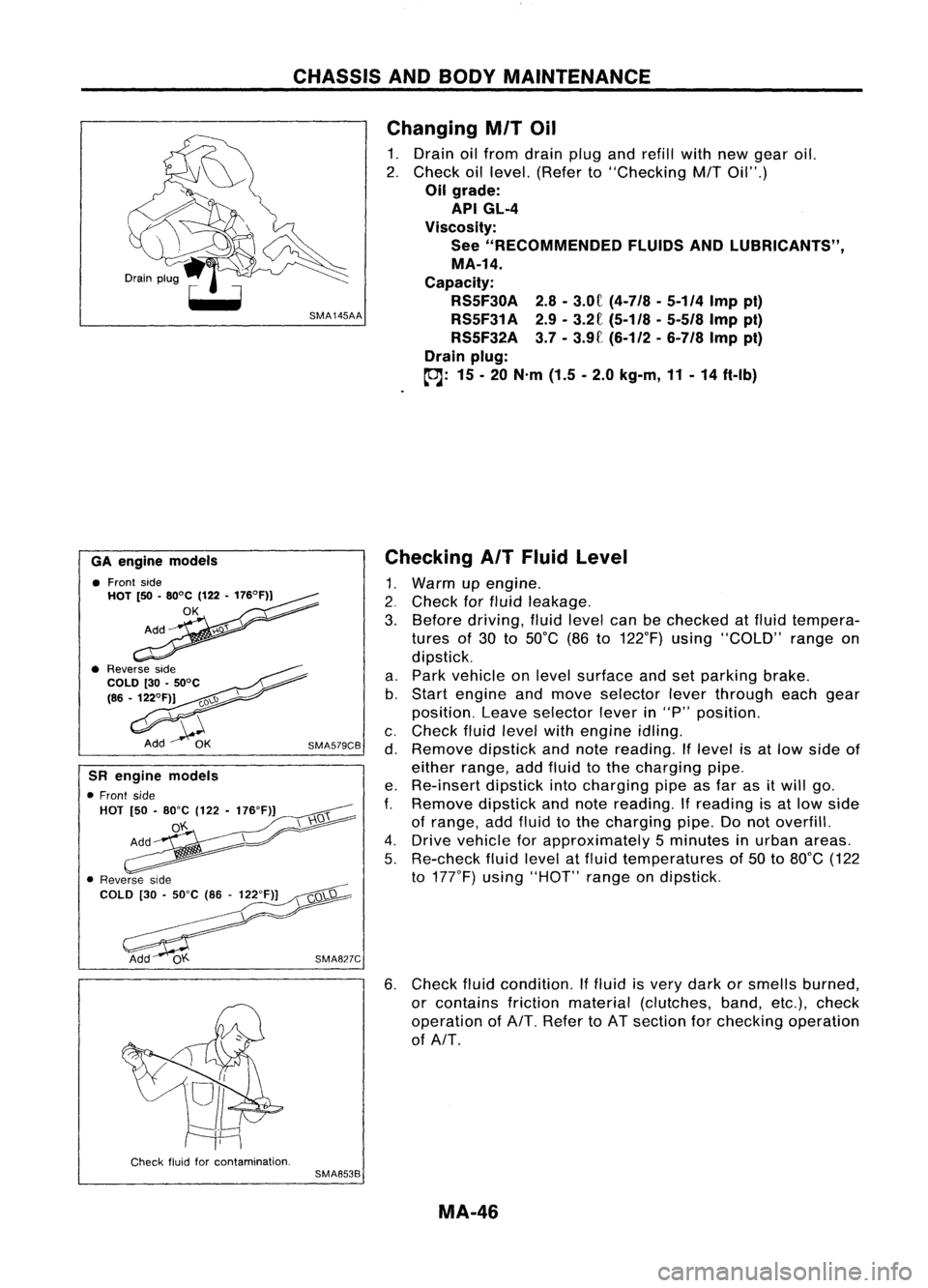
1. Drain oilfrom drain plugandrefill withnewgear oil.
2. Check oillevel. (Refer to"Checking
M/T
Oil".)
Oil grade:
API GL-4
Viscosity: See "RECOMMENDED FLUIDSANDLUBRICANTS",
MA-14.
Capacity: RS5F30A 2.8-3.0f
(4-7/8 -5-114
Imppi)
RS5F31A 2.9-3.2£
(5-1/8 -5-518
Imppt)
RS5F32A 3.7-3.9£ (6-112 -
6-7/8
Imppt)
Drain plug:
(OJ:
15-20 N'm (1.5-2.0 kg-m, 11-14 ft-Ib)
6. Check fluidcondition. Iffluid isvery dark orsmells burned,
or contains frictionmaterial (clutches, band,etc.),check
operation ofAlT. Refer toAT section forchecking operation
of AlT.
Checking
AIT
Fluid Level
1. Warm upengine .
2. Check forfluid leakage.
3. Before driving, fluidlevel canbechecked atfluid tempera-
tures of30 to50°C (86to122°F) using"COLD" rangeon
dipstick.
a. Park vehicle onlevel surface andsetparking brake.
b. Start engine andmove selector leverthrough eachgear
position. Leaveselector leverin"P" position.
c. Check fluidlevel withengine idling.
d. Remove dipstickandnote reading. Iflevel isat low side of
either range, addfluid tothe charging pipe.
e. Re-insert dipstickintocharging pipeasfar asitwill go.
f.
Remove dipstickandnote reading.
If
reading isat low side
of range, addfluid tothe charging pipe.Donot overfill.
4. Drive vehicle forapproximately 5minutes inurban areas.
5. Re-check fluidlevel atfluid temperatures of50 to80°C (122
to 177°F) using"HOT" rangeondipstick.
SMA827C
SMA579CB
GA
engine models
• Front side
HOT [50•80°C (122•176°F))
OK
SR engine models
• Front side
HOT [50•80"C (122-176"F)]
o'f..
Check fluidforcontamination.
SMA853B
MA-46
Page 1533 of 1701
CHASSISANDBODY MAINTENANCE
OK MINMax,
line
Min, line
SBR418C Changing
AITFluid
1. Warm up
AIT
fluid.
2. Stop engine.
3. Drain
AIT
fluid from drain plugandrefill withnew
AIT
fluid .•
Always refillwithsame volume asdrained fluid.
i
Fluid grade:
Genuine NissanATForequivalent
See "RECOMMENDED FLUIDSANDlUBRICANTS",
MA-14.
Fluid capacity (Withtorque converter):
7.0£
(6-1/8
Impqt)
Drain plug:
toJ:
29.39
N'm
(3.0-4.0
kg-m,
22-29
ft-Ib)
4. Run engine atidle speed forfive minutes.
5. Check fluidlevel andcondition. Referto"Checking
AIT
Fluid". Iffluid isstill dirty, repeat steps2through 5.
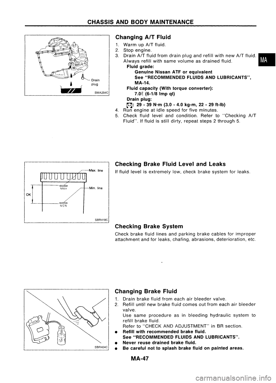
Checking BrakeFluidLevel andLeaks
If
fluid level isextremely low,check brakesystem forleaks.
Checking BrakeSystem
Check brakefluidlines andparking brakecables forimproper
attachment andforleaks, chafing, abrasions, deterioration, etc.
SBR404C Changing
BrakeFluid
1. Drain brake fluidfrom each airbleeder valve.
2. Refill untilnewbrake fluidcomes outfrom each airbleeder
valve. Use same procedure asinbleeding hydraulic systemto
refill brake fluid.
Refer to"CHECK ANDADJUSTMENT" inBR section.
• Refill withrecommended brakefluid.
See "RECOMMENDED FLUIDSANDlUBRICANTS".
• Never reusedrained brakefluid.
• Becareful nottosplash brakefluidonpainted areas.
MA-47
Page 1617 of 1701
SRA696A
SRA697A
S
Control rod
Lateral link
~H";""I"
ITorsion
beam
SRA698AREAR
SUSPENSION
Removal andInstallation
CAUTION:
• Before removing therear suspension assembly,disconnect
the ABS wheel sensor fromtheassembly. Failuretodo so
may result indamage tothe sensor wiresandthesensor
becoming inoperative.
• Remove suspension assembly.
1. Disconnect brakehydraulic linesandparking brakecableat
toggle lever.(Models withdrum brakes.)
• Drain brake fluidbefore disconnecting brakelines.
2. Disconnect parkingbrakecablefromcaliper andremove
brake caliper androtor. (Models withdiscbrakes.)
Suspend caliperassembly withwire soasnot tostretch brake
hose.
Be careful nottodepress brakepedal, orpiston willpop out.
Make surebrake hoseisnot twisted.
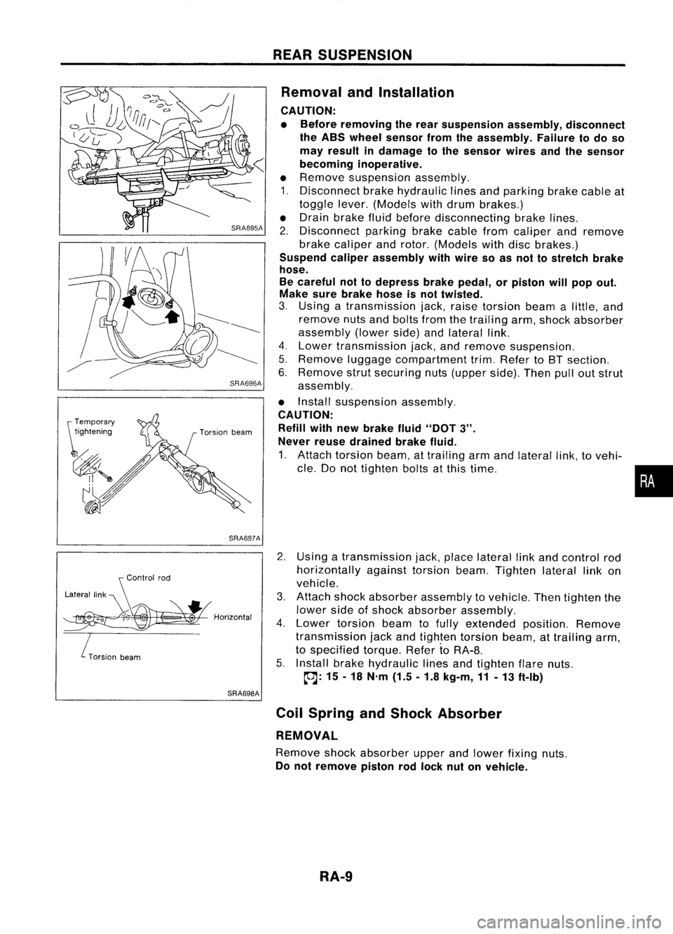
3. Using atransmission jack,raise torsion beamalittle, and
remove nutsandbolts fromthetrailing arm,shock absorber
assembly (lowerside)andlateral link.
4. Lower transmission jack,andremove suspension.
5. Remove luggagecompartment trim.Refer toBT section.
6. Remove strutsecuring nuts(upper side).Thenpulloutstrut
assembly.
• Install suspension assembly.
CAUTION: Refill withnewbrake fluid"DOT
3".
Never reusedrained brakefluid.
1. Attach torsion beam,attrailing armandlateral link,tovehi-
cle. Donot tighten boltsatthis time.
2. Using atransmission jack,place lateral linkand control rod
horizontally againsttorsionbeam.Tighten laterallinkon
vehicle.
3. Attach shockabsorber assembly tovehicle. Thentighten the
lower sideofshock absorber assembly.
4. Lower torsion beamtofully extended position.Remove
transmission jackandtighten torsion beam,attrailing arm,
to specified torque.RefertoRA-8.
5. Install brakehydraulic linesandtighten flarenuts.
~: 15-18 N'm (1.5.1.8 kg-m,11-13 ft-Ib)
Coil Spring andShock Absorber
REMOVAL
Remove shockabsorber upperandlower fixing nuts.
Do not remove pistonrodlock nutonvehicle.
RA-9
•
Page 1673 of 1701
SST491B
SST090B ON-VEHICLE
SERVICE
Bleeding Hydraulic System
1. Raise frontendofvehicle untilwheels areclear ofthe
ground.
2. Add fluid intooiltank tospecified level.Thenquickly turn
steering wheelfullytoright andleftand lightly touchsteer-
ing stoppers.
Repeat steering wheeloperation untilfluid level nolonger
decreases.
3. Start engine.
Repeat step2.above.
• Incomplete airbleeding willcause thefollowing tooccur.
When thishappens, bleedairagain.
a. Air bubbles inreservoir tank
b. Clicking noiseinoil pump
c. Excessive buzzinginoil pump
Fluid noise mayoccur inthe valve oroil pump. Thisiscommon
when thevehicle isstationary orwhile turning thesteering
wheel slowly. Thisdoes notaffect theperformance ordurabil-
ity ofthe system.
Checking SteeringWheelTurning Force(For
power steering)
1. Park vehicle onalevel, drysurface andsetparking brake.
2. Start engine.
3. Bring power steering fluiduptoadequate operating temper-
ature. [Make suretemperature offluid isapproximately 60
to 80°C (140to176°F).]
Tires needtobe inflated tonormal pressure.
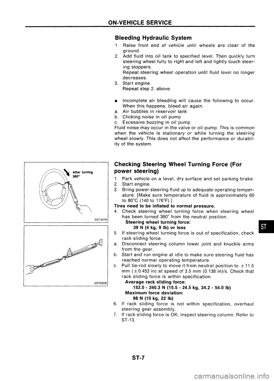
4. Check steering wheelturning forcewhen steering wheel
has been turned 360°from theneutral position.
Steering wheelturning force: •
39 N(4 kg, 9Ib) orless
5.
If
steering wheelturning forceisout ofspecification, check
rack sliding force.
a. Disconnect steeringcolumnlowerjointandknuckle arms
from thegear.
b. Start andrunengine atidle tomake suresteering fluidhas
reached normaloperating temperature.
c. Pull tie-rod slowlytomove itfrom neutral position to
::l::
11.5
mm
(::l::
0.453 in)atspeed of3.5 mm (0.138 in)/s.Check that
rack sliding forceiswithin specification.
Average racksliding force:
152.0 -240.3 N(15.5 -24.5 kg,34.2 -54.0 Ib)
Maximum forcedeviation:
98 N(10 kg, 22Ib)
6.
If
rack sliding forceisnot within specification, overhaul
steering gearassembly.
7. Ifrack sliding forceisOK, inspect steering column.Referto
ST-13.
ST-7