Page 302 of 1701

l
--,II
~//
SBR656
SBR026D REAR
DISCBRAKE
Disassembly (Cont'd)
c. Remove pistonseal.
Be careful nottodamage cylinderbody.
4. Remove returnspring, toggleleverandcable guide.
Inspection -Caliper
CAUTION: Use brake fluidtoclean cylinder. Neverusemineral
oil.
CYLINDER BODY
• Check insidesurface ofcylinder forscore, rust,wear, dam-
age orpresence offoreign objects. Ifany ofthe above con-
ditions areobserved, replacecylinder body.
• Minor damage fromrustorforeign objects maybeelimi-
nated bypolishing surfacewithafine emery paper.
Replace cylinder bodyifnecessary.
TORQUE MEMBER
Check forwear, cracks orother damage. Replaceifnecessary.
PISTON
CAUTION:
Piston sliding surface ;splated. Donot polish withemery paper
even ifrust orforeign objects isstuck tosliding surface.
Check pistonforscore, rust,wear, damage orpresence offor-
eign objects. Replace ifany ofthe above conditions are
observed.
SLIDE PIN,PINBOLT, ANDPINBOOT
Check forwear, cracks orother damage.
Replace ifany ofthe above conditions areobserved.
BR-32
Page 305 of 1701
SBR646REAR
DISCBRAKE
Assembly (Cont'd)
8. Insert piston sealintogroove oncylinder body.
9. With piston bootfitted topiston, insertpiston bootinto
groove oncylinder bodyandfitpiston byturning itclock-
wise withlong nose pliers, orsuitable tool.
Commercial
service
1001
SBR868C
10.Fittoggle lever,return spring andcable guide.
Installation
CAUTION:
• Refill withnewbrake fluid"DOT 3"or"DOT
4".
• Never reusedrained brakefluid.
• Donot mix different typesofbrake fluids(DOT3,DOT
4).
1. Install caliper assembly.
2. Install brakehosetocaliper securely.
3. Install allparts andsecure allbolts.
4. Bleed air.Refer to"Bleeding Procedure", BR-6.
BR-35
•
Page 313 of 1701
ANTI-LOCKBRAKESYSTEM
Removal andInstallation (Cont'd)
1. Disconnect batterycable.
2. Drain brake fluid.Refer toSR-5.
3. Discharge airconditioner refrigerant.RefertoHA section
("R-134a ServiceProcedure", "SERVICEPROCEDURES").
4. Disconnect allconnectors fromASSrelay bracket.
5. Remove mounting boltforrelay bracket.
6. Remove ASSrelay boxwith bracket.
7. Remove airconditioner low-pressure tubes.RefertoHA
section, ("Refrigerant Lines","SERVICE PROCEDURES") .
8. Disconnect brakepipesandmove awayfromactuator.
It is not necessary toremove thesepipesfromvehicle.
9. Remove/loosen mountingnutsbetween actuatorand
bracket.
BR-43
•
Page 314 of 1701
ANTI-LOCKBRAKESYSTEM
Removal andInstallation (Cont'd)
10. Draw outASS actuator asshown.
ASS
actuator
SBR039D CAUTION:
After installation, payattention tothe following points:
• Refill brake fluidandbleed air.Refer to"CHECK AND
ADJUSTMENT", BR-5and"AIR BLEEDING", BR.6,respec-
tively.
• Charge airconditioner refrigerant.RefertoHA section,
("R-134a ServiceProcedure", "SERVICEPROCEDURES").
• The installation procedureisthe reverse ofremoval.
ASS
actuator
_-=--=--=--=--_-_-\,_~
""'~t"
b"ok.,
SBR040D
ABSRELAYS
1. Disconnect batterycable.
2. Remove ASSrelay cover.
BR-44
Page 322 of 1701

TROUBLEDIAGNOSES
Contents
How toPerform TroubleDiagnoses forQuick andAccurate Repair SR-52
Self-diagnosis SR-53
CONSULT BR-58
CONSULT Inspection Procedure BR-59
Component PartsandHarness Connector Location BR-64
Preliminary Check BR-65
Ground CircuitCheck BR-66
Circuit Diagram forQuick Pinpoint Check BR-67
Diagnostic Procedure1Warning lampdoes notcome on BR-68
Diagnostic Procedure2Warning lampstays on BR-69
Diagnostic Procedure3ABS actuator solenoid valve BR-72
Diagnostic Procedure 4Wheel sensor orrotor BR-74
Diagnostic Procedure5Motor relayormotor BR-76
Diagnostic Procedure6Solenoid valverelay BR-79
Diagnostic Procedure7Power supply BR-81
Diagnostic Procedure 8Control unit BR-82
Diagnostic Procedure9Pedal vibration andnoise BR-82
Diagnostic Procedure10Long stopping distance BR-83
Diagnostic Procedure11Unexpected pedalaction BR-83
Diagnostic Procedure12ABS does notwork BR-84
Diagnostic Procedure13ABS works frequently BR-84
Electrical Component Inspection BR-85
How toPerform TroubleDiagnoses forQuick
and Accurate Repair
INTRODUCTION
The ABS system hasanelectronic controlunittocontrol major
functions. Thecontrol unitaccepts inputsignals fromsensors
and instantly drivestheactuators. Itis essential thatboth kinds
of signals areproper andstable. Itis also important tocheck
for conventional problems:suchasair leaks inbooster lines,
lack ofbrake fluid,orother problems withthebrake system.
SEF233G
Itis much moredifficult todiagnose aproblem thatoccurs
intermittently ratherthancontinuously. Mostintermittent prob-
lems arecaused bypoor electric connections orfaulty wiring.
In this case, careful checking ofsuspicious circuitsmayhelp
prevent thereplacement ofgood parts.
A visual checkonlymaynotfind thecause ofthe problems, so
a road testshould beperformed.
Before undertaking actualchecks, takejustafew minutes to
talk with acustomer whoapproaches withaABS complaint. The
customer isavery good source ofinformation onsuch prob-
lems; especially intermittent ones.Through thetalks withthe
customer, findoutwhat symptoms arepresent andunder what
SEF234G
conditions theyoccur.
Start yourdiagnosis bylooking for"conventional" problems
first. Thisisone ofthe best ways totroubleshoot brakeprob-
lems onanABS controlled vehicle.
BR-52
Page 333 of 1701

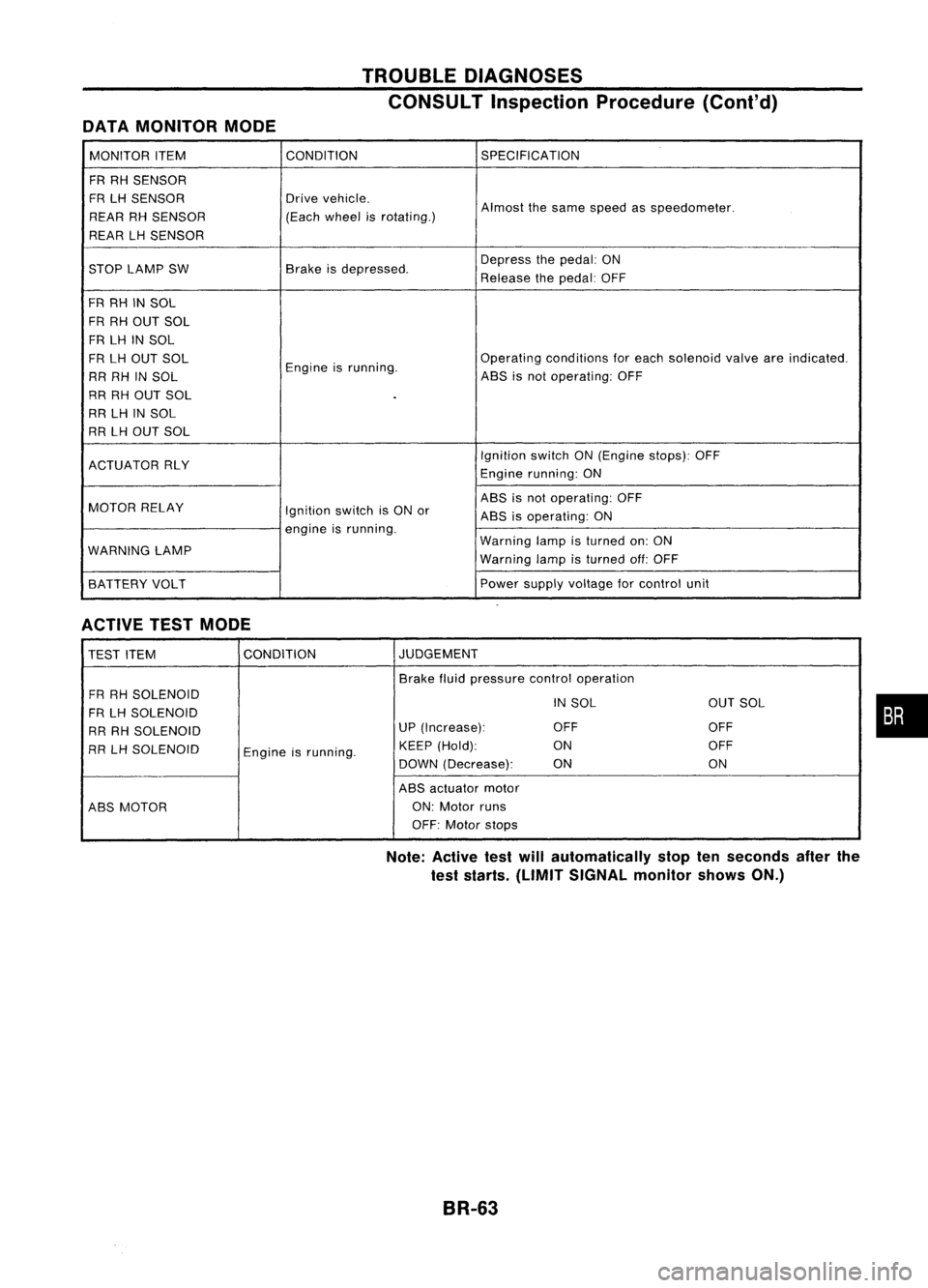
DATAMONITOR MODE TROUBLE
DIAGNOSES
CONSULT Inspection Procedure(Cont'd)
MONITOR ITEM CONDITION
SPECIFICATION
FR RH SENSOR
FR LHSENSOR Drive
vehicle.
Almostthesame speed asspeedometer.
REAR RHSENSOR (Each
wheel isrotating.)
REAR LHSENSOR
STOP LAMP SW Brake
isdepressed. Depress
thepedal: ON
Release thepedal: OFF
FR RH INSOL
FR RH OUT SOL
FR LH INSOL
FR LH OUT SOL
Engineisrunning. Operating
conditions foreach solenoid valveareindicated.
RR RH INSOL ABS
isnot operating: OFF
RR RH OUT SOL
.
RR LHINSOL
RR LHOUT SOL
IgnitionswitchON(Engine stops):OFF
ACTUATOR RLY
Enginerunning: ON
MOTOR RELAY ABS
isnot operating: OFF
Ignition switchisON or
ABSisoperating: ON
engine isrunning.
WARNING LAMP Warning
lampisturned on:ON
Warning lampisturned off:OFF
BATTERY VOLT Power
supply voltage forcontrol unit
ACTIVE TESTMODE
TEST ITEM CONDITION JUDGEMENT
Brake fluidpressure controloperation
FR RH SOLENOID
INSOL OUTSOL
FR LH SOLENOID
RR RH SOLENOID UP
(Increase): OFF OFF
RR LHSOLENOID
Engineisrunning. KEEP
(Hold): ON OFF
DOWN (Decrease): ON ON
ABS actuator motor
ABS MOTOR ON:
Motor runs
OFF: Motor stops
Note: Active testwillautomatically stoptenseconds afterthe
test starts. (LIMIT SIGNAL monitorshowsON.)
BR-63
•
Page 335 of 1701

TROUBLEDIAGNOSES
OK
Max
line
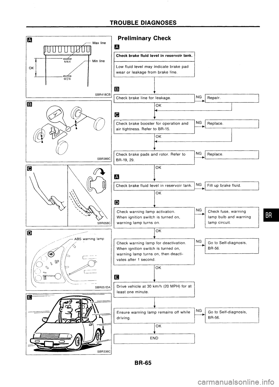
Min line Preliminary
Check
m
Check brakefluidlevel inreservoir tank.
Low fluid level mayindicate brakepad
wear orleakage frombrake line.
SBR418CB
Checkbrakelineforleakage. NG
Repair.
Check brakefluidlevel inreservoir tank.NGFillupbrake fluid.
OK
•
Check
fuse,warning
lamp bulbandwarning
lamp circuit.
Replace.
NG
NG
Replace.
NG
OK
OK OK
t
Check brakebooster foroperation and
air tightness. RefertoBR-15.
Check brakepadsandrotor. Referto
BR-19,29.
Check warning lampactivation.
When ignition switchisturned on,
SBR058C
warninglampturns on.
SBR389C
-~--
iii' -,/"
ASS,:"arnlng lamp
/~
,/~
/ //>Jf,
I
/' " /-..,J
C
~" ,J \)
003
i
,A',.!.,
(')
~---
(-ji=o -[--
~"
-,--
'-,--_ ..
OK
Check warning lampfordeactivation.
When ignition switchisturned on,
warning lampturns on,then deacti.
vates after1second.
OK NG
GotoSelf-diagnosis,
BR-56.
SBR051DA
Drivevehicle at30 km/h (20MPH) forat
least oneminute.
Ensure warning lampremains offwhile
driving.
OK
END
NG
GotoSelf-diagnosis,
BR-56.
BR-65
Page 354 of 1701

TROUBLEDIAGNOSES
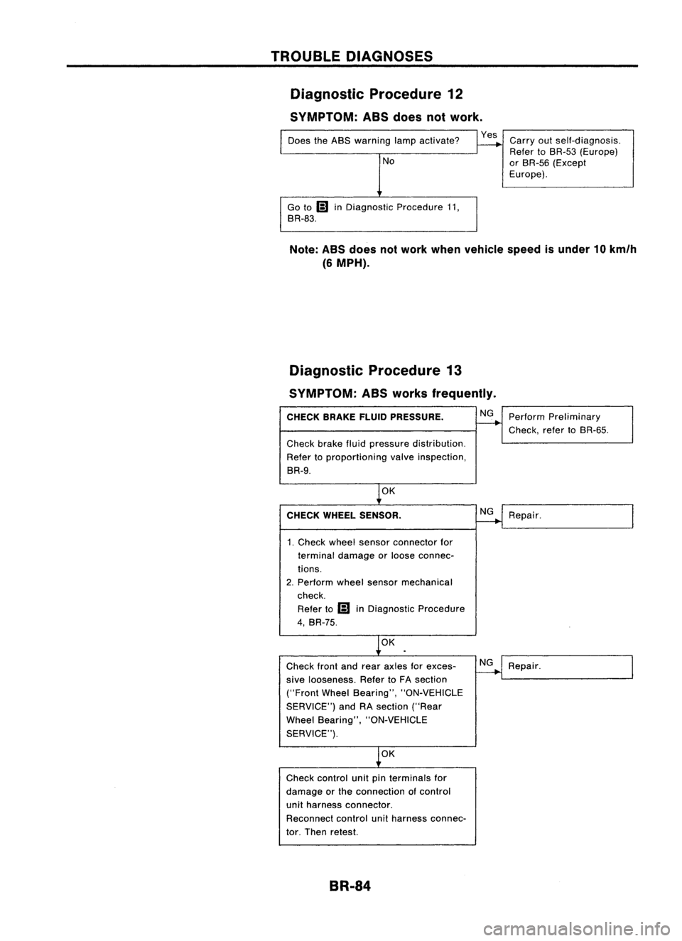
Diagnostic Procedure12
SYMPTOM: ASSdoes notwork.
Does theABS warning lampactivate?
No
Go to
Ii)
inDiagnostic Procedure11,
BR-83.
Yes
Carryoutself-diagnosis.
Refer toBR-53 (Europe)
or BR-55 (Except
Europe).
Note: ABSdoes notwork when vehicle speedisunder 10km/h
(6 MPH).
Diagnostic Procedure13
SYMPTOM: ASSworks frequently.
CHECK BRAKEFLUIDPRESSURE.
Check brakefluidpressure distribution.
Refer toproportioning valveinspection,
BR-9.
OK
CHECK WHEEL SENSOR.
1. Check wheelsensor connector for
terminal damage orloose connec-
tions.
2. Perform wheelsensor mechanical
check.
Refer to
Ii)
inDiagnostic Procedure
4, BR-75.
OK
Check frontandrear axles forexces-
sive looseness. RefertoFA section
("Front WheelBearing", "ON-VEHICLE
SERVICE") andRAsection ("Rear
Wheel Bearing", "ON-VEHICLE
SERVICE").
OK
Check control unitpinterminals for
damage orthe connection ofcontrol
unit harness connector.
Reconnect controlunitharness connec-
tor. Then retest.
BR-84 NG
NG
NG
Perform
Preliminary
Check, refertoBR-55.
Repair.
Repair.