Page 275 of 1701
CHECKANDADJUSTMENT
OK
MINMax.
line
Min. line
SBR418C
Checking
BrakeFluidLevel
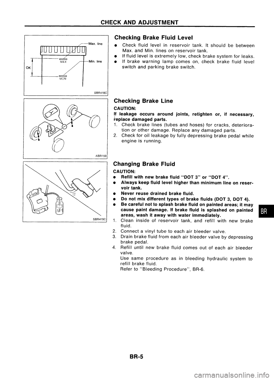
• Check fluidlevel inreservoir tank.Itshould bebetween
Max. andMin. lines onreservoir tank.
• Iffluid level isextremely low,check brakesystem forleaks.
• Ifbrake warning lampcomes on,check brakefluidlevel
switch andparking brakeswitch.
ABR159
SBR419C
Checking
BrakeLine
CAUTION: If leakage occursaround joints,retighten or,ifnecessary,
replace damaged parts.
1. Check brakelines(tubes andhoses) forcracks, deteriora-
tion orother damage. Replaceanydamaged parts.
2. Check foroilleakage byfully depressing brakepedalwhile
engine isrunning.
Changing BrakeFluid
CAUTION:
• Refill withnewbrake fluid"DOT 3"or"DOT 4".
• Always keepfluidlevel higher thanminimum lineonreser-
voir tank.
• Never reusedrained brakefluid.
• Donot mix different typesofbrake fluids(DOT3,DOT 4).
• Becareful nottosplash brakefluidonpainted areas;itmay •
cause paintdamage. Ifbrake fluidissplashed onpainted :•
areas, washitaway withwater immediately.
1. Clean inside ofreservoir tank,andrefill withnewbrake
fluid.
2. Connect avinyl tubetoeach airbleeder valve.
3. Drain brake fluidfrom each airbleeder valvebydepressing
brake pedal.
4. Refill untilnewbrake fluidcomes outofeach airbleeder
valve.
Use same procedure asinbleeding hydraulic systemto
refill brake fluid.
Refer to"Bleeding Procedure", BR-6.
BR-5
Page 276 of 1701
SBR995
SBR419C AIR
BLEEDING
Bleeding Procedure
CAUTION:
• Carefully monitorbrakefluidlevel atmaster cylinder during
bleeding operation.
• Ifmaster cylinder issuspected tohave airinside, bleedair
from master cylinder first.Refer to"Installation", "MASTER
CYLINDER", BR-12.
• Fill reservoir withnewbrake fluid"DOT 3"or"DOT
4".
Make sureitis full atall times whilebleeding airout of
system.
• Donot mix different typesofbrake fluids(DOT3,DOT 4).
• Place acontainer undermaster cylinder toavoid spillage of
brake fluid.
• For models withABS, turnignition switchOFFanddiscon-
nect ABS actuator connector orbattery cable.
• Bleed airinthe following order:
I
RHO models
I
Left rear brake-+Right frontbrake-+Right rearbrake-+Left
front brake
I
LAD models
I
Right rearbrake-+Left frontbrake-+Left rearbrake-+Right
front brake.
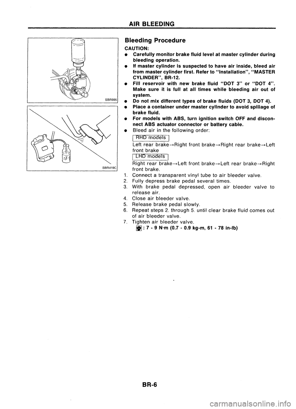
1. Connect atransparent vinyltubetoair bleeder valve.
2. Fully depress brakepedalseveral times.
3. With brake pedaldepressed, openairbleeder valveto
release air.
4. Close airbleeder valve.
5. Release brakepedalslowly.
6. Repeat steps2.through 5.until clear brake fluidcomes out
of air bleeder valve.
7. Tighten airbleeder valve.
~: 7-
9 N.m (0.7-0.9 kg-m, 61-78 in-Ib)
BR-6
Page 278 of 1701
BRAKEHYDRAULIC LINE
SBR419C
For tightening flarenut
~GG94310000
or
commercial equivalent
SBR820BA
Removal
CAUTION: • Becareful nottosplash brakefluidonpainted areas;itmay
cause paintdamage. Ifbrake fluidissplashed onpainted
areas, washitaway withwater immediately.
• Allhoses mustbefree from excessive bending,tWistingand
pulling.
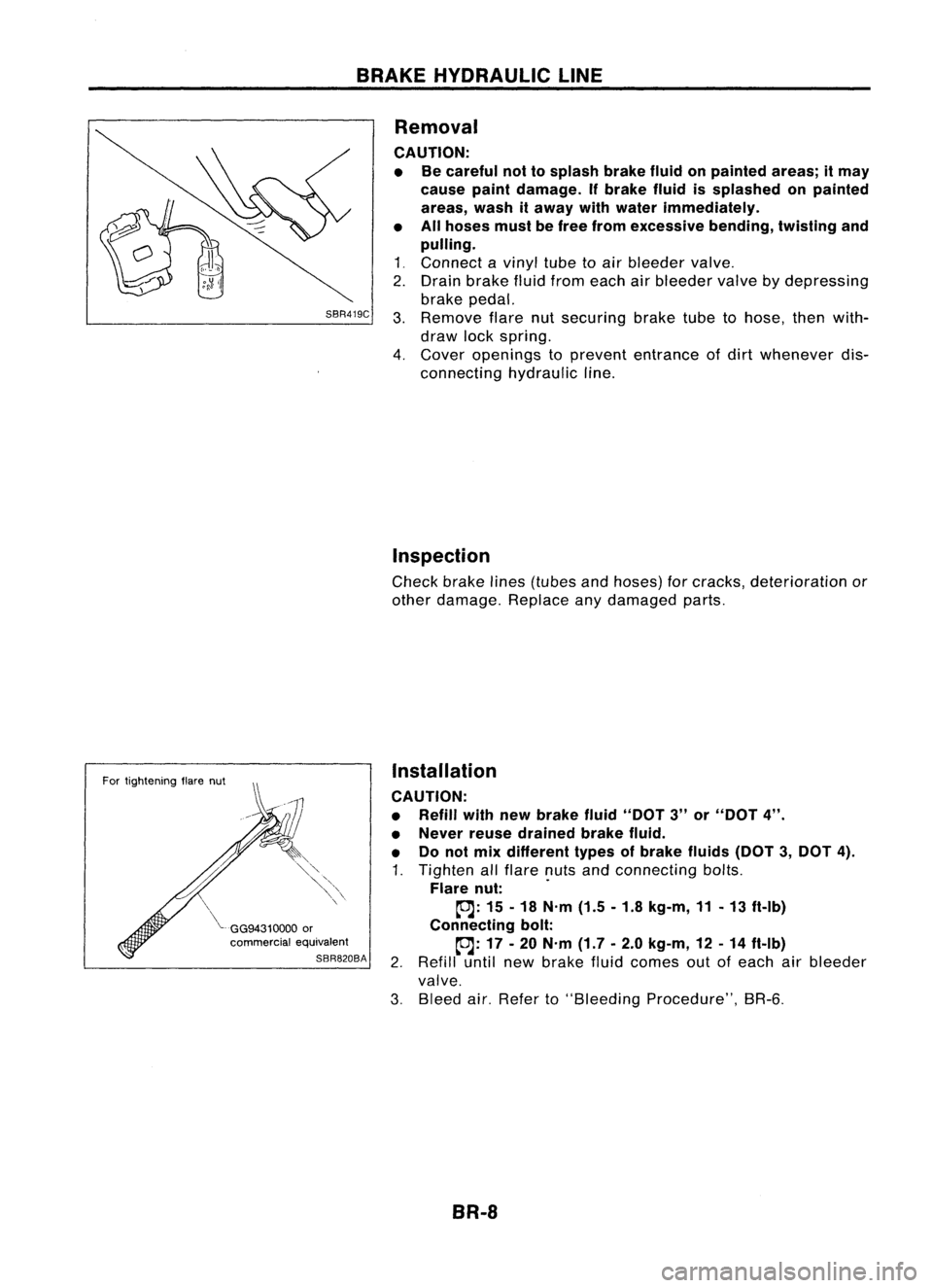
1 ~ Connect a
vinyl
tubetoair bleeder
valve~
2. Drain brake fluidfrom each airbleeder
valve
bydepressing
brake pedal.
3. Remove
flarenutsecuring braketubetohose, thenwith-
draw lockspring.
4. Cover
openings to
prevent
entrance ofdirt
whenever
dis-
connecting hydraulicline.
Inspection
Check brakelines(tubes andhoses) forcracks, deterioration or
other damage. Replaceanydamaged parts.
Installation
CAUTION:
• Refill withnewbrake fluid"DOT 3"or"DOT 4".
• Never reusedrained brakefluid.
• Donot mix different typesofbrake fluids(DOT3,DOT 4).
1. Tighten allflare nutsandconnecting bolts.
Flare nut: .
~: 15-18 N'm (1.5-1.8 kg-m, 11-13 ft-Ib)
Connecting bolt:
~: 17-20 N'm (1.7-2.0 kg-m, 12-14 ft-Ib)
2. Refill untilnewbrake fluidcomes outofeach airbleeder
valve.
3. Bleed air.Refer to"Bleeding Procedure", BR-6.
BR-8
Page 279 of 1701

CONTROLVALVE
Proportioning Valve
INSPECTION
CAUTION:
• Carefully monitorbrakefluidlevel atmaster cylinder.
• Use new brake fluid"DOT 3"or"DOT 4".
• Donot mix different typesofbrake fluids(DOT3,DOT 4).
• Becareful nottosplash brakefluidonpainted areas;itmay
cause paintdamage. Ifbrake fluidissplashed onpaint
areas, washitaway withwater immediately.
• Depress pedalslowly whenraising frontbrake pressure.
• Check rearbrake pressure 2seconds afterfront brake pres-
sure reaches specified value.
• For models withABS disconnect harnessconnectors from
ABS actuator relaybefore checking.
1.
Connect Tooltoair bleeders offront andrear brakes on
either
LH
or
RH
side.
2. Bleed airfrom theTool.
3. Check rearbrake pressure bydepressing brakepedal
(increasing frontbrake pressure).
Unit:kPa(bar, kg/cm
2,
psi)
Without ABS
I
With
ABS
Applied models
GA14DE,GA16DE,CD20 GA16DE'
SR20DE
Applied pressure 7.3556.375
5,394
(Front brake) (73.6,
75,1,067) (63.7,65,924)
(53.9,55,782)
3,432 -3,825 2,452-2,844
Output pressure 5,100
-5,492 (34.3-38.2, (245-28.4,
(Rear brake) (51.0
-54.9, 52-56, 739 -796) 35-39, 25-29,
498 -555) 356-412)
*
Models forAustralia
If
output pressure isout ofspecifications, replacedualpro- •••
portioning valve(separated type)ormaster cylinder assem-
bly (built-in type).
4. Bleed airafter disconnecting theTool. Refer to"Bleeding
Procedure", BR-5.
BR-9
Page 280 of 1701
CONTROLVALVE
Proportioning Valve(Cont'd)
REMOVAL (Separated type)
CAUTION:
• Becareful nottosplash brakefluidonpainted areas;itmay
cause paintdamage. Ifbrake fluidissplashed onpainted
areas, washitaway withwater immediately.
• Allhoses mustbefree from excessive bending,twistingand
pulling.
1. Connect avinyl tubetoair bleeder valve.
2. Drain brake fluidfrom each airbleeder valvebydepressing
brake pedal.
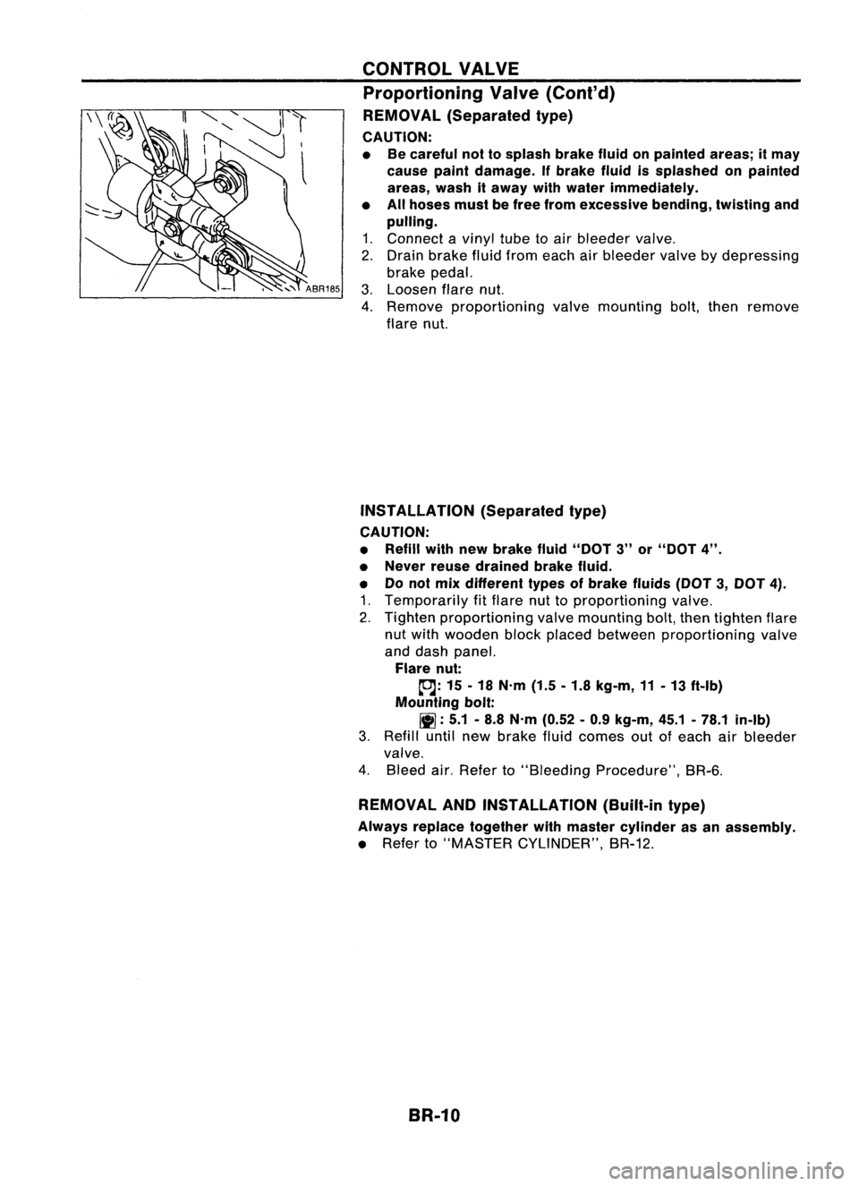
3. Loosen flarenut.
4. Remove proportioning valvemounting bolt,then remove
flare nut.
INSTAllATION (Separatedtype)
CAUTION:
• Refill withnewbrake fluid"DOT 3"or"DOT 4".
• Never reusedrained brakefluid.
• Donot mix different typesofbrake fluids(DOT3,DOT 4).
1. Temporarily fitflare nuttoproportioning valve.
2. Tighten proportioning valvemounting bolt,then tighten flare
nut with wooden blockplaced between proportioning valve
and dash panel.
Flare nut:
tDJ:
15-18 N'm (1.5-1.8 kg-m, 11-13 ft-Ib)
Mounting bolt:
11]:
5.1-8.8 N'm (0.52 -0.9 kg-m, 45.1-78.1 in-Ib)
3. Refill untilnewbrake fluidcomes outofeach airbleeder
valve.
4. Bleed air.Refer to"Bleeding Procedure", BR-6.
REMOVAL ANDINSTAllATION (Built-intype)
Always replace together withmaster cylinder asan assembly.
• Refer to"MASTER CYLINDER", BR-12.
BR-10
Page 282 of 1701
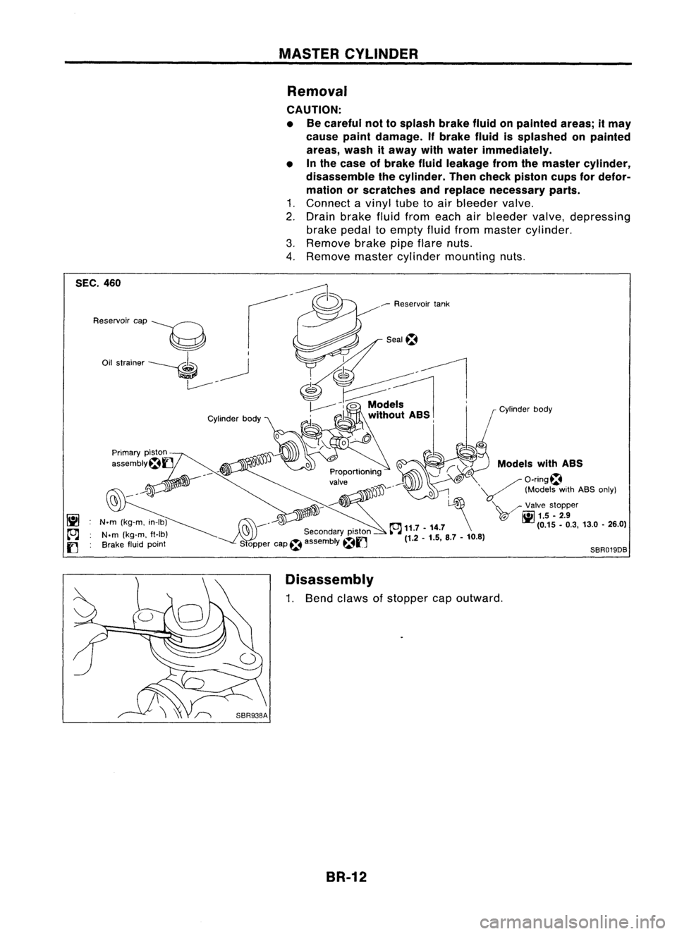
MASTERCYLINDER
Removal
CAUTION:
• Becareful nottosplash brakefluidonpainted areas;itmay
cause paintdamage. Ifbrake fluidissplashed onpainted
areas, washitaway withwater immediately.
• Inthe case ofbrake fluidleakage fromthemaster cylinder,
disassemble thecylinder. Thencheck piston cupsfordefor-
mation orscratches andreplace necessary parts.
1. Connect avinyl tubetoair bleeder valve.
2. Drain brake fluidfrom each airbleeder valve,depressing
brake pedaltoempty fluidfrom master cylinder.
3. Remove brakepipeflare nuts.
4. Remove mastercylinder mounting nuts.
Models withASS
/O-ring~
'V
(ModelswithABS only)
'\~ /'Valve stopper
T@" ~
1.5.2.9
(0.15.0.3, 13.0•26.0)
o
l-~
~ 11.7 -14.7 \
(1.2 -1.5, 8.7-10.8)
SBR019DB
Seal~
___
Reservoir tank
jJ'JD~----
~ ..-:'J
C'9 ---
Secondarypiston
Stopper cap~assembly
~f]
Cylinder
body
N.m (kg-m, in-Ib)
N.m (kg-m. ft-Ib)
Brake fluidpoint
Reservoir
cap
----g
Oil strainer ----. ~
L------- -
SEC.
460
Disassembly
1. Bend claws ofstopper capoutward.
BR-12
Page 284 of 1701
SBR435BMASTER
CYLINDER
Assembly (Cont'd)
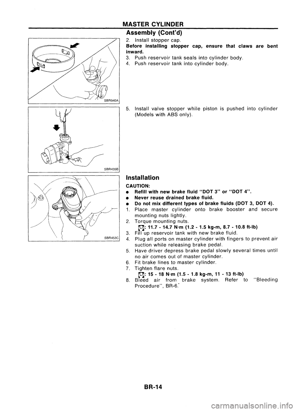
2. Install stopper cap.
Before installing stoppercap,ensure thatclaws arebent
inward.
3. Push reservoir tankseals intocylinder body.
4. Push reservoir tankintocylinder body.
5. Install valvestopper whilepiston ispushed intocylinder
(Models withABS only).
Installation
CAUTION:
• Refill withnewbrake fluid"DOT 3"or"DOT 4".
• Never reusedrained brakefluid.
• Donot mix different typesofbrake fluids(DOT3,DOT 4).
1. Place master cylinder ontobrake booster andsecure
mounting nutslightly.
2. Torque mounting nuts.
~: 11.7 -14.7 N'm(1.2-1.5 kg-m, 8.7-10.8 ft-Ib)
3. Fillupreservoir tankwith newbrake fluid.
4. Plug allports onmaster cylinder withfingers toprevent air
suction whilereleasing brakepedal.
5. Have driver depress brakepedalslowly several timesuntil
no air comes outofmaster cylinder.
6. Fitbrake linestomaster cylinder.
7. Tighten flarenuts.
~: 15-18 N'm (1.5-1.8 kg-m, 11-13 ft-Ib)
8. Bleed airfrom brake system. Referto"Bleeding
Procedure", BR-6."
BR-14
Page 285 of 1701
OKNGBRAKE
BOOSTER
On-vehicle Service
OPERATING CHECK
• Depress brakepedalseveral timeswithengine off.After
exhausting vacuum,makesurethere isno change inpedal
stroke.
• Depress brakepedal, thenstart engine. Ifpedal goesdown
slightly, operation isnormal.
AIRTIGHT CHECK
• Start engine, andstop itafter oneortwo minutes. Depress
SBR002A
brakepedalseveral timesslowly. Booster isairtight ifpedal
stroke isless each time.
• Depress brakepedalwhileengine isrunning, andstop
engine withpedal depressed. Thepedal stroke should not
change afterholding pedaldownfor
30seconds.
SBR365AA Removal
CAUTION:
• Becareful nottosplash brakefluidonpainted areas;itmay
cause paintdamage. Ifbrake fluidissplashed onpainted
areas, washitaway withwater immediately.
• Be careful nottodeform orbend brake pipes, during
removal ofbooster.
SEC.
465.470
BR-15Gasket
~ :N.m (kg-m. ft-Ib)
SBR223BB
•