Page 994 of 1701

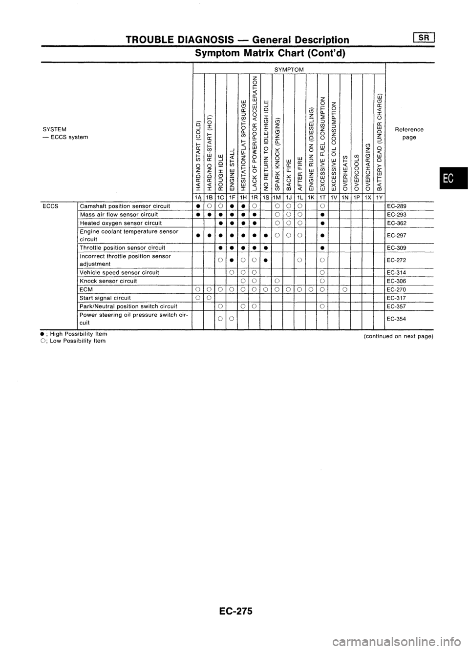
TROUBLEDIAGNOSIS -General Description
Symptom MatrixChart(Cont'd)
SYMPTOM
z
0
1=
0::
Z
W
w w
CJ
..J
W
0
Z
CJ
W
..J
1=
0
0::
0::
()
9
5
Q.
1=
::::>
()
z
:2
I
i='
en
I
5
::;
Q.
()
is'
0
;:::
CJ
::::>
:2
0::
~
0::
:r:
z
w
en
::::>
SYSTEM
..J
0
0
en
z
w
Reference
0
Q.
W
e;
w
en
0
- ECCS system
~
....
en
0
..J
Z
9-
0
z
Z
0::
Q.
9
a:
()
0
2-
page
....
....
ii:
..J
U
....
Z
CJ
0::
..J
W
0
W
..J
0
en
..J
u-
s:
.... ::.:::
0
::::>
0
z
W
..J
U
u-
e;
....
w
Z
0
z
0
w
z
(/)
en
w
en
0::
..J
....
Q.
W
::::>
w
w
....
..J
0::
0
0 0
9
en
0
0::
Z
0::0::
0::
>>
0
>-
~
u-
::::>::.:::
u:
enen
0
I
Z Z
W
0
....
u:
w
W
0::
2i 2i
I
Z
W
::.:::
0::
z
en
(/)
I
()
()
w
CJ
e;
....
::.:::
0:: 0::
::.:::
w w
W
0::
0::
0::
1=
0::
0::
::::>
en
()
()
....
e;
uu
w
w
w
0
Z
w
0
Q.
u-
Z
x x
> >>
I I
0::
W
I
..J
Z
(/)
1Il
w
w w
000
1Il
11\ 18
1C 1F
1H 1R
1S1M 1J1L1K
1T
1V1N 1P1X
1Y
ECCS Camshaft
positionsensorcircuit
•
0
0
••
0
000 0
EC-289
Mass airflow sensor circuit
•••
•••
0
00
•
EC-293
Heated oxygen sensorcircuit
••
••
0
00
•
EC-362
Engine coolant temperature sensor
••• ••
•
•
0
0
0
•
EC-297
circuit
Throttle positionsensorcircuit
••
••
• •
EC-309
Incorrect fhrottleposition sensor
0
•
0
0
•
0
0
EC-272
adjustment
Vehicle speedsensor circuit
000
0
EC-314
Knock sensor circuit
00
0 0
EC-306
ECM
0
0
0
0
00000
0
00 0
EC-270
Start signal circuit
00
EC-317
Park/Neutral positionswitchcircuit
000
0
EC-357
Power steering oilpressure switchcir-
0
0
EC-354
cuit
•
• ;High Possibility Item
0;
Low Possibility Item
EC-275
(continued
onnext page)
Page 1099 of 1701
INJECTIONNOZZLE ~
Test andAdjustment (Cont'd)
LEAKAGE TEST
1. Maintain thepressure atabout 981to1,961 kPa(9.8to19.6
bar, 10to20 kg/cm
2,
142to284 psi) below initialinjection
pressure.
2. Check thatthere isno dripping fromthenozzle tiporaround
the body.
Good
Faulty
SEF674A
3.Ifthere isleakage, clean,overhaul orreplace nozzle.
Good
I
Wrong
•
EF794 SPRAY
PATTERN TEST
1. Pump thetester handle onetime persecond.
2. Check thespray pattern .
3. Ifthe spray pattern isnot correct, cleanorreplace nozzle.
EC-380
Page 1113 of 1701
![NISSAN ALMERA N15 1995 Service Manual TROUBLEDIAGNOSES
Quick-glow System(Cont'd)
~
ill]
SEF941P
Ii]
~i5
Glow
Eill~
plug
0
@]Q]
2
[ill
~SEF942P INSPECTION
START
Check fuellevel, fuelsupplying system,
~Correct.
starter motor NISSAN ALMERA N15 1995 Service Manual TROUBLEDIAGNOSES
Quick-glow System(Cont'd)
~
ill]
SEF941P
Ii]
~i5
Glow
Eill~
plug
0
@]Q]
2
[ill
~SEF942P INSPECTION
START
Check fuellevel, fuelsupplying system,
~Correct.
starter motor](/manual-img/5/57349/w960_57349-1112.png)
TROUBLEDIAGNOSES
Quick-glow System(Cont'd)
~
ill]
SEF941P
Ii]
~i5
Glow
Eill~
plug
0
@]Q]
2
[ill
~SEF942P INSPECTION
START
Check fuellevel, fuelsupplying system,
~Correct.
starter motor,etc.
OK
m
Check thatallglow plugconnecting
~Installproperly.
plate nutsareinstalled properly.
OK
CHECK OVERALL FUNCTION. OK
CHECK COMPONENT
Check entirequick-glow system.(Refer
---..
(Glowplug).
to "System Operation Check"onnext See
page EC-397.
page.)
NG
CHECK POWER SUPPLY ANDGROUND NG
Repair harness orcon-
CIRCUIT.
---..
nector.
(Refer to"Power Supplyandground
circuit forECM", EC-396).
OK
(!]
CHECK VOLTAGE BETWEEN GLOW NG
Check thefollowing.
RELA YAND GROUND.
---..
•7.5A fuse
1) Check voltage between terminals •
75A fusible link
G), @and ground withtester. •Harness continuity
Voltage: Batteryvoltage between
glowrelay
OK and
fuse
If NG, repair harness or
connectors.
[!1
CHECK OUTPUT SIGNALCIRCUIT. NG
Repair harness orcon-
1) Check harness continuity between
---+
nectors.
ECM terminal
@
andterminal @.
Continuity shouldexist.
OK
Ii]
CHECK HARNESS CONTINUITY NG
Repair harness orcon-
BETWEEN GLOWRELAY ANDGLOW
---+
nectors.
PLUG. 1) Disconnect ECMharness connector.
2) Disconnect glowrelay.
3) Check harness continuity between
glow relay terminal
@
and glow
plug.
Continuity shouldexist.
~OK
SEF940P
SEF939P
-"-.....
'y;-----...
Connecting platenut:J
~1.0 •1.5
N.mr-
"(0.1 •0.15 kg-m,- ""'-
8.7 -13.0 in-Ib)
~
""
.
'------
~
~
ECM
E1
CONNECTOR
II
106
II
(!]
~io
EC-394
Page 1165 of 1701

ENGINELUBRICATION SYSTEM
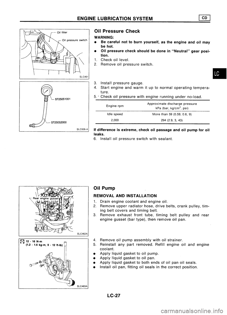
SLC926.A Ifdifference isextreme, checkoilpassage andoilpump foroil
leaks.
6. Install oilpressure switchwithsealant.
ST25052000
3.
Install pressure gauge.
4. Start engine andwarm itup tonormal operating tempera-
ture.
5 .. Check oilpressure withengine running underno-load.
•
Approximate dischargepressure
kPa (bar,
kg/cm
2,
psi)
More than59(0.59, 0.6,9)
294 (2.9, 3,43)
Idle
speed
2,000
Engine
rpm
Oil
Pressure Check
WARNING: • Becareful nottoburn yourself, asthe engine andoilmay
be hot.
• Oilpressure checkshould bedone in"Neutral" gearposi-
tion.
1. Check oillevel.
2. Remove oilpressure switch.
SLC461
Oil
pressure switch
ST25051 001
~ 12.16 N.m
(1.2 .1.6 kg-m, 9-
12 ft.lb) SLC462A
SLC463A Oil
Pump
REMOVAL ANDINSTAllATION
1. Drain engine coolant andengine oil.
2. Remove upperradiator hose,drivebelts, crank pulley, tim-
ing belt covers andtiming belt.
3. Remove exhaustfronttube, timing beltpulley andrear
engine gusset(bartype), thenremove oilpan.
4. Remove oilpump assembly withoilstrainer.
5. Reinstall anypart removed. Refillengine oiland engine
coolant.
• Apply liquidgasket tooil pump.
• Apply liquidgasket tooil pan.
• Apply liquidgasket toboth ends ofoil pan oilseals.
• Install oilpan, fitting oilseals inthe correct position.
LC-27
Page 1200 of 1701

Looseninnumerical order.
SEM546D TIMING
CHAIN @KJ
Removal (Cont'd)
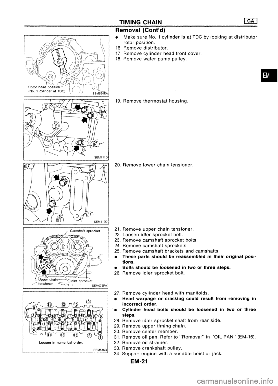
• Make sureNo.1 cylinder isat TDC bylooking atdistributor
rotor position.
16. Remove distributor.
17. Remove cylinder headfrontcover.
18. Remove waterpumppulley.
19. Remove thermostat housing.
20. Remove lowerchaintensioner.
21. Remove upperchaintensioner.
22. Loosen idlersprocket bolt.
23. Remove camshaft sprocketbolts.
24. Remove camshaft sprockets.
25. Remove camshaft bracketsandcamshafts.
• These partsshould bereassembled intheir original posi-
tions.
• Bolts should beloosened intwo orthree steps.
26. Remove idlersprocket bolt.
27. Remove cylinderheadwithmanifolds.
• Head warpage orcracking couldresult fromremoving in
incorrect order.
• Cylinder headboltsshould beloosened intwo orthree
steps.
28. Remove idlersprocket shaftfromrearside.
29. Remove uppertiming chain.
30. Remove centermember.
31. Remove oilpan. Refer to"Removal" in"OIL PAN" (EM-16).
32. Remove oilstrainer.
33. Remove crankshaft pulley.
34. Support enginewithasuitable hoistorjack.
EM-21
•
Page 1217 of 1701
I
Recess
1
diameter
I
SEM795A CYLINDER
HEAD
Inspection (Cont'd)
VALVE SEATS
Check valveseats forpitting atcontact surface. Resurface or
replace ifexcessively worn.
• Before repairing valveseats, checkvalveandvalve guide
for wear. Ifthey have worn, replace them.Thencorrect
valve seat.
• Cut with both hands touniform thecutting surface.
REPLACING VALVESEATFORSERVICE PARTS
1. Bore outold seat until
it
collapses. Setmachine depthstop
so that boring cannot contact bottomfaceofseat recess in
cylinder head.
2. Ream cylinder headrecess.
Reaming boreforservice valveseat
Oversize [0.5mm(0.020 in)]:
Unit:mm(in)
Engine model GA16DE
withoutVTC,
GA16DE withVTC
14DE and15DE
30.500 -30.516
Intake (1.2008
-1.2014)
31.500-31.516
31.500 -31.516
(1.2402-1.2408)
(1.2402 -1.2408).
Exhaust 25.500
-25.516
26.500-26.516
(1.0039 -1.0046)
(1.0433-1.0439)
.: GA 16DE without VTC
Use thevalve guide center forreaming toensure valveseatwill
have thecorrect fit.
EM-38
Page 1231 of 1701

AB
Taper:A-B
Out-at-round: X-
y
Oil groove
y
SEM316A
SEM366E CYLINDER
BLOCK ~
Inspection (Cont'd)
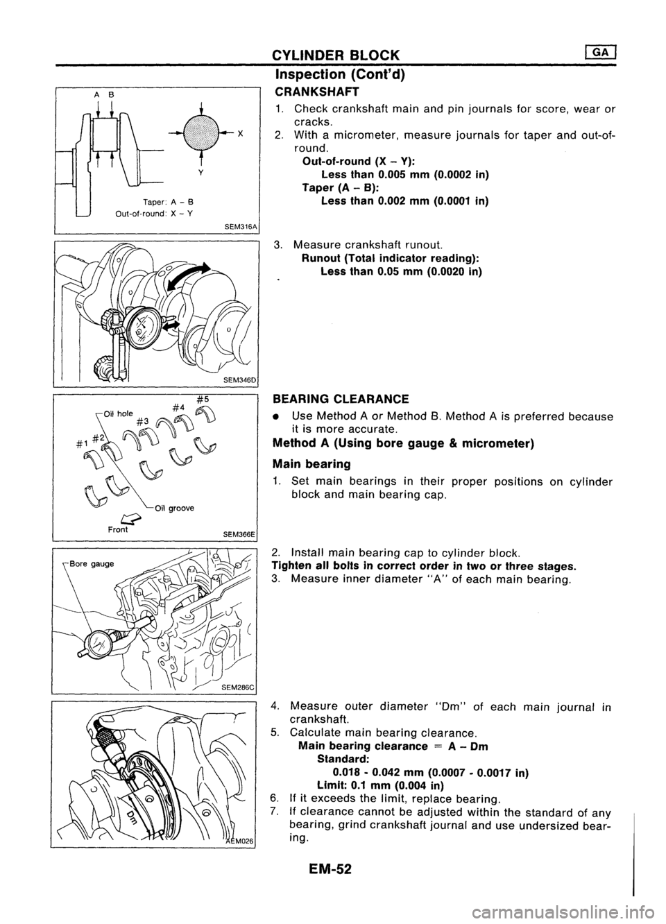
CRANKSHAFT
1. Check crankshaft mainandpinjournals forscore, wearor
cracks.
2. With amicrometer, measurejournalsfortaper andout-of-
round.
Out-of-round (X-V):
Less than0.005 mm(O.0002 in)
Taper (A-B):
Less than0.002 mm(O.0001 in)
3. Measure crankshaft runout.
Runout (Totalindicator reading):
Less than0.05mm(O.0020 in)
BEARING CLEARANCE
• Use Method Aor Method B.Method Ais preferred because
it is more accurate.
Method A(Using boregauge µmeter)
Main bearing
1. Set main bearings intheir proper positions oncylinder
block andmain bearing cap.
2. Install mainbearing captocylinder block.
Tighten allbolts incorrect orderintwo orthree stages.
3. Measure innerdiameter "A"ofeach main bearing.
4. Measure outerdiameter "Om"ofeach mainjournal in
crankshaft.
5. Calculate mainbearing clearance.
Main bearing clearance
=
A-
Om
Standard:
0.018 .0.042 mm(O.0007 .0.0017 in)
Limit: 0.1mm (O.004 in)
6. Ifitexceeds thelimit, replace bearing.
7. Ifclearance cannotbeadjusted withinthestandard ofany
bearing, grindcrankshaft journalanduseundersized bear-
ing.
EM-52
Page 1235 of 1701
Punchmarksideup
(if mark ispresent.)
SEM965E CYLINDER
BLOCK @KJ
Assembly (Coni'd)
3. Set piston ringsasshown.
CAUTION:
• When piston ringsarenotreplaced, makesurethatpiston
rings aremounted intheir original position.
• When piston ringsarebeing replaced andnopunch mark
is present, pistonringscanbemounted witheither sideup.
For Europe andIsrael models
Engine
front
Q
Oil
ring
expander
tf
V
;l
Top and second ring
Punch marksideup
(if mark ispresen!.)
.::::::::J
c::
Oil ring
expander
*c:
Engine
il
front
~ •
Top ring
• Oil ring
~ upperrail
IJ
/') Oilring
~ ~lower rail
SEM160B
SEM208F
Top ring
Oil ring
~ It
upper rail
!J
~.Oil ring
lower rail
SEM200F Except
forEurope andIsrael models
#5
#4 ~
Oil hole #3 ~-'U
~"\)~ ~
~~
Oilgroove
SEM366E
CRANKSHAFT
1. Set main bearings intheir proper positions oncylinder
block andmain bearing cap.
• Confirm thatcorrect mainbearings areused. Referto
"Inspection" (EM-52).
• Apply engine oiltobearing surfaces.
EM-56