1995 NISSAN ALMERA N15 Correct
[x] Cancel search: CorrectPage 1332 of 1701

2. Apply engine oiltomain bearing surfaces oncrankshaft
journal side.
3. Install crankshaft and")
Enginefront1
t;J
SEM230F
~~~:::~"
IJ
~ 2ndring
SEM909 CYLINDER
BLOCK
[ill
Assembly (Cont'd)
2. Apply engine oiltomain bearing surfaces oncrankshaft
journal side.
3. Install crankshaft andmain bearing caps.
Main bearing capbolt:
~: 44-54 N'm (4.5-5.5 kg-m, 33-40 ft-Ib)
4. Tighten mainbearing capbolts.
• Arrange theparts sothat theindicated numbersonbearing •
caps areinarow from thefront ofengine.
• Tighten bearing capbolts gradually intwo orthree stages
and outwardly fromcenter bearing insequence.
• After securing bearingcapbolts, ascertain thatcrankshaft
turns smoothly.
• Apply newengine oiltothreads ofbearing capbolts.
5. Measure crankshaft freeendplay atcenter bearing.
Crankshaft freeendplay:
Standard 0.05 -0.18 mm(0.0020 -0.0071 in)
Limit 0.30 mm(0.0118 in)
PISTON WITHCONNECTING ROD
1. Install connecting rodbearings inthe connecting rodsand
connecting rodcaps.
• Confirm thatcorrect sizeofbearings isused.
Refer to"Inspection" (EM-147).
• Install thebearings sothat theoilhole inthe connecting rod
aligns withtheoilhole ofthe bearing.
• Apply engine oiltoconnecting rodbearing surfaces onthe
crankshaft journalside.
• Set piston ringsasshown.
EM-153
Page 1356 of 1701
PRECAUTIONS
Observe thefollowing precautions toensure safeandproper
servicing.
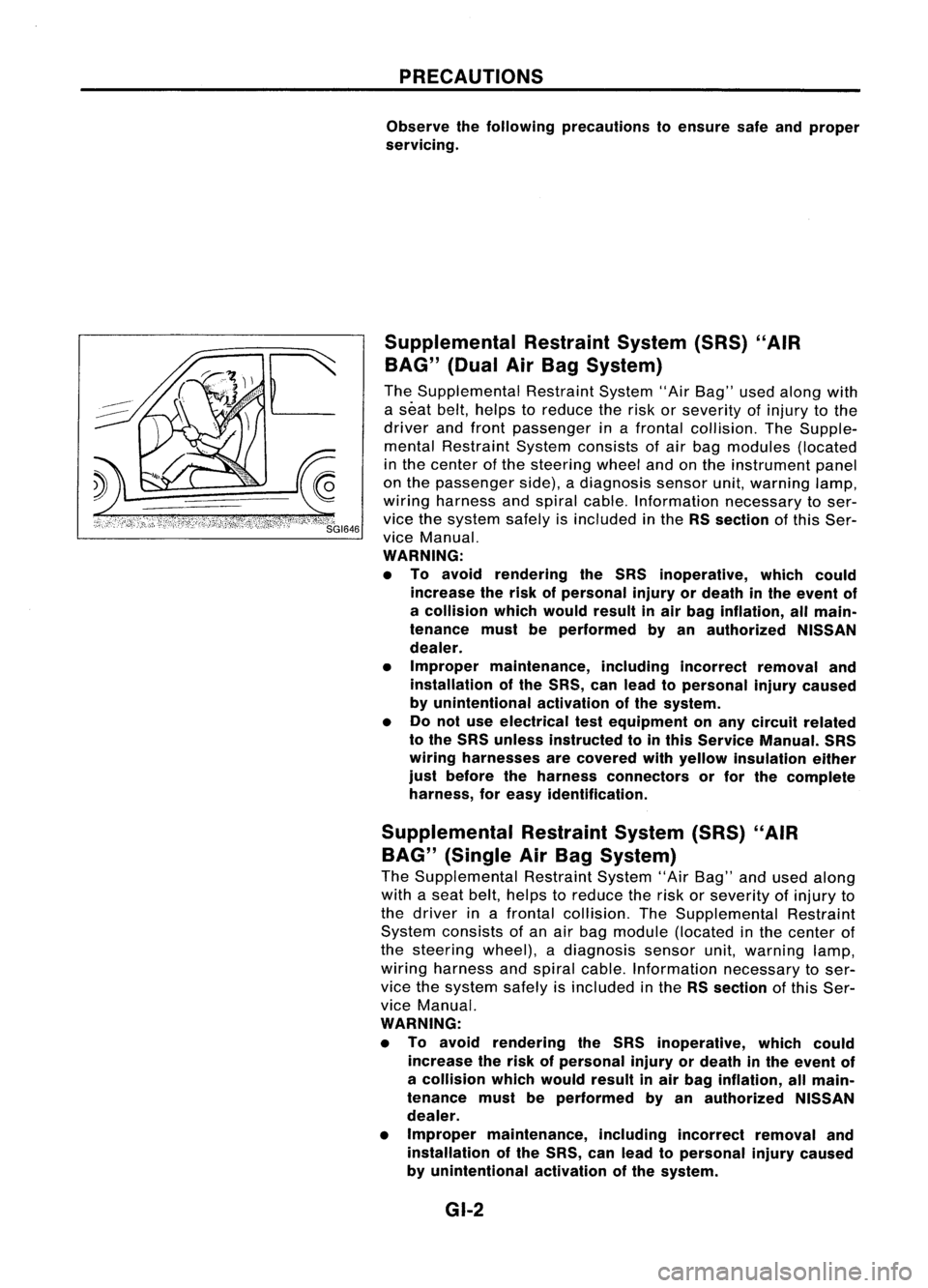
Supplemental RestraintSystem(SRS)"AIR
BAG" (DualAirBag System)
The Supplemental RestraintSystem"AirBag" usedalong with
a seat belt,helps toreduce therisk orseverity ofinjury tothe
driver andfront passenger inafrontal collision. TheSupple-
mental Restraint Systemconsists ofair bag modules (located
in the center ofthe steering wheelandonthe instrument panel
on the passenger side),adiagnosis sensorunit,warning lamp,
wiring harness andspiral cable. Information necessarytoser-
vice thesystem safelyisincluded inthe RSsection ofthis Ser-
vice Manual.
WARNING:
• To avoid rendering theSRS inoperative, whichcould
increase therisk ofpersonal injuryordeath inthe event of
a collision whichwould resultinair bag inflation, allmain-
tenance mustbeperformed byan authorized NISSAN
dealer.
• Improper maintenance, includingincorrectremovaland
installation ofthe SRS, canlead topersonal injurycaused
by unintentional activationofthe system.
• Donot use electrical testequipment onany circuit related
to the SRS unless instructed tointhis Service Manual. SRS
wiring harnesses arecovered withyellow insulation either
just before theharness connectors orfor the complete
harness, foreasy identification.
Supplemental RestraintSystem(SRS)"AIR
BAG" (Single AirBag System)
The Supplemental RestraintSystem"AirBag" andused along
with aseat belt, helps toreduce therisk orseverity ofinjury to
the driver inafrontal collision. TheSupplemental Restraint
System consists ofan air bag module (located inthe center of
the steering wheel),adiagnosis sensorunit,warning lamp,
wiring harness andspiral cable. Information necessarytoser-
vice thesystem safelyisincluded inthe RSsection ofthis Ser-
vice Manual.
WARNING:
• To avoid rendering theSRS inoperative, whichcould
increase therisk ofpersonal injuryordeath inthe event of
a collision whichwould resultinair bag inflation, allmain-
tenance mustbeperformed byan authorized NISSAN
dealer.
• Improper maintenance, includingincorrectremovaland
installation ofthe SRS, canlead topersonal injurycaused
by unintentional activationofthe system.
GI-2
Page 1377 of 1701

•SHORT CIRCUIT
• SHORT TOGROUND
HOW
TOPERFORM EFFICIENT DIAGNOSIS FORANELECTRICAL INCIDENT
Circuit Inspection
•
A circuit isopen when thereisno continuity throughasection ofthe circuit.
There aretwo types ofshorts.
Whenacircuit contacts anothercircuitandcauses the
normal resistance tochange.
When acircuit contacts aground sourceandgrounds the
circuit.
INTRODUCTION
In general, testingelectrical circuitsisan easy taskifitis approached inalogical andorganized method.
Before beginning itis important tohave allavailable information onthe system tobe tested. Also,get
a thorough understanding ofsystem operation. Thenyouwillbeable touse theappropriate equipment
and follow thecorrect testprocedure.
You may have tosimulate vehiclevibrations whiletesting electrical components.
Gentlyshake
thewir-
ing harness orelectrical component todo this.
OPEN
SHORT
TESTING FOR"OPENS" INTHE CIRCUIT
[YJ
(Voltage check)
Before
youbegin todiagnose andtestthesystem, youshould roughsketch aschematic ofthe system.
This willhelp youtologically walkthrough thediagnosis process.Drawingthesketch willalso reinforce
your working knowledge ofthe system.
Inspection foropens
-+
DMM
Ll
~SE. ~L9~K
I
I
I __-,----
B + SIDE
I
OPEN
I I
A
L
-.J
[ill
DMM
SGI846
Continuity checkmethod
The continuity checkisused tofind anopen inthe circuit. TheDigital Multimeter (DMM)setonthe
resistance functionwillindicate anopen circuit asover limit(OL,nobeep toneorno ohms symbol). Make
sure toalways startwiththeDMM atthe highest resistance level.
To help inunderstanding thediagnosis ofopen circuits pleaserefertothe schematic above.
1. Disconnect thebattery negative cable.
2. Start atone end ofthe circuit andwork yourwaytothe.other end.(Atthe fuse block inthis exam-
ple)
3. Connect oneprobe ofthe DMM tothe fuse block terminal onthe load side.
4. Connect theother probe tothe fuse block (power) sideofSW1. Littleorno resistance willindicate
that portion ofthe circuit hasgood continuity. Ifthere wereanopen inthe circuit, theDMM would
indicate anover limitorinfinite resistance condition.(pointA)
5. Connect theprobes between SW1andtherelay. Littleorno resistance willindicate thatportion of
the circuit hasgood continuity. Ifthere wereanopen inthe circuit, theDMM would indicate anover
limit orinfinite resistance condition.(pointB)
6. Connect theprobes between therelay andthesolenoid. Littleorno resistance willindicate thatpor-
tion ofthe circuit hasgood continuity. Ifthere wereanopen inthe circuit, theDMM would indicate
an over limitorinfinite resistance condition.(pointC)
Any circuit canbediagnosed usingtheapproach inthe above example.
GI-23
Page 1386 of 1701

CONSULTCHECKING SYSTEM
Function andSystem Application
Diagnostic FunctionECCSAirbag ASS NATS*1
test mode
Thismode enables atechnician toadjust somedevices
Work support fasterandmore accurately byfollowing theindications on
x
- --
CONSULT.
Self-diagnostic Self-diagnosticresultscanberead anderased quickly.
x
x x
x
results
ECU discriminated Classification
numberofareplacement ECUcanberead to
-
x
- -
No. preventanincorrect ECUfrom being installed.
Data monitor Input/Output
datainthe ECM canberead.
x
-
x
-
Diagnostic TestMode inwh.ich CONSULT drivessomeactua-
Active test tors
apart fromtheECMs andalso shifts some parameters
x
-
x
-
in aspecified range.
ECM partnumber ECM
partnumber canberead.
x
-
x
-
Function test Conducted
byCONSULT insteadofatechnician todetermine
x
- --
whether eachsystem is"OK" or"NG".
Control unitinitiali- Allregistered ignitionkeyIDsinNATS components canbe
- -
-
x
sation initialisedandnew IDscan beregistered.
Self-function checkECM
checks itsown NATS communication interface.
--
-
x
x :Applicable
*1: NATS: Nissan Anti-Theft System
LithiumBatteryReplacement
CONSUL Tcontains alithium battery. Whenreplacing thebattery obeythefollowing:
WARNING: Replace thelithium battery withSANYO ElectricCo.,ltd., CR2032 only.Useofanother batterymay
present arisk offire orexplosion. Thebattery maypresent afire orchemical burnhazard ifmistreated.
Do not recharge, disassemble ordispose ofinfire.
Keep thebaitery outofreach ofchildren anddiscard usedbattery conforming tothe local regulations.
Checking Equipment
When ordering thebelow equipment, contactyourNISSAN distributor.
Tool name
NISSAN CONSULT
CD
CONSULT unit
and accessories
@
Program card(EE940)
(AE930)*1, (AE950)*2,
(NATS-E940)*3 Description
NT004
* 1: For Australia
*2: Regarding ASSforAustralia, arevised program card(AE950) willbeapplicable tothis system in1995.
*3: An order forNATS program cardmust beplaced onlywithNISSAN EUROPE N.V.
GI-32
Page 1404 of 1701
\"AIR
BAG\" (DualAirBag System)
The Supplemental RestraintSystem\"AirBag\" usedalong withaseat belt,helps toreduce therisk or
se")
PRECAUTIONSANDPREPARATION
Supplemental RestraintSystem(SRS)"AIR
BAG" (DualAirBag System)
The Supplemental RestraintSystem"AirBag" usedalong withaseat belt,helps toreduce therisk or
severity ofinjury tothe driver andfront passenger inafrontal collision. TheSupplemental Restraint
System consists ofair bag modules (locatedinthe center ofthe steering wheelandonthe instrument
panel onthe passenger side),adiagnosis sensorunit,warning lamp,wiring harness andspiral cable.
Information necessarytoservice thesystem safelyisincluded inthe
RSsection
ofthis Service Manual.
WARNING:
• Toavoid rendering theSRS inoperative, whichcouldincrease therisk ofpersonal injuryordeath
in the event ofacollision whichwould resultinair bag inflation, allmaintenance mustbeperformed
by an authorized NISSANdealer.
• Improper maintenance, includingincorrectremovalandinstallation ofthe SRS, canlead topersonal
injury caused byunintentional activationofthe system.
• Donot use electrical testequipment onany circuit related tothe SRS unless instructed tointhis
Service Manual. SRSwiring harnesses arecovered withyellow insulation eitherjustbefore the
harness connectors orfor the complete harness,foreasy identification.
Supplemental RestraintSystem(SRS)"AIR
BAG" (Single AirBag System)
The Supplemental RestraintSystem"AirBag" andused along withaseat belt,helps toreduce therisk
or severity ofinjury tothe driver inafrontal collision. TheSupplemental RestraintSystemconsists of
an air bag module (located inthe center ofthe steering wheel),adiagnosis sensorunit,warning lamp,
wiring harness andspiral cable. Information necessarytoservice thesystem safelyisincluded inthe
RS section
ofthis Service Manual.
WARNING: • Toavoid rendering theSRS inoperative, whichcouldincrease therisk ofpersonal injuryordeath
in the event ofacollision whichwould resultinair bag inflation, allmaintenance mustbeperformed
by anauthorized NISSANdealer.
• Improper maintenance, includingincorrectremovalandinstallation ofthe SRS, canlead topersonal
injury caused byunintentional activationofthe system.
• Donot use electrical testequipment onany circuit related tothe SRS unless instructed tointhis
Service Manual.
HA-2
Page 1426 of 1701

TROUBLEDIAGNOSES
Performance TestDiagnoses
INSUFFICIENT COOLING
INSUFFICIENT COOLING
CHECK AIRFLOW.
OK CHECK
BLOWER MOTOROPERATION.
OK
CHECK COMPRESSOR OPERATION.
OK Clogged
blowerinlet!
Clogged duct/Loose duct
connection/Air leakage,etc.
@
(Go to
next
page.)
(Go to
next page.)
OK CHECK HIGHANDLOW SIDE PRESSURE. USE
PERFORMANCE CHART.(RefertoHA-26.)
NG
RECOVER REFRIGERANT USINGRECOVERY
RECYCLING EQUIPMENT ANDCHARGE SPECI-
FIED AMOUNT OFREFRIGERANT.
CHECK HIGHANDLOW SIDE PRESSURE. USE
PERFORMANCE CHART.(RefertoHA-26.)
OK
CHECK DISCHARGE AIRTEMPERATURE. USE
PERFORMANCE CHART.(RefertoHA-26.)
NG
Malfunctioning temperaturecontroloperation
(air mix door position improperly adjusted)/
Malfunctioning watercockoperation (incorrect
valve closure)
Note:
Fa-Ii
correspond tothose inTROUBLE DIAGNOSES FOR
ABNORMAL PRESSURE.
(Refer toHA-27.)
HA-24NG
Note
BOTH HIGHANDLOW
m
PRESSURE SIDESARE
TOO HIGH.
HIGH PRESSURE SIDEIS
(;]
TOO HIGH ANDLOW
PRESSURE SIDEISTOO
LOW.
HIGH PRESSURE SIDEIS
TOO LOW ANDLOW
PRESSURE SIDEISTOO
HIGH.
BOTH HIGHANDLOW
Ii]
PRESSURE SIDESARE
TOO LOW.
LOW PRESSURE SIDE
SOMETIMES BECOMES
NEGATIVE.
LOW PRESSURE SIDE
Ii
BECOMES NEGATIVE.
Page 1429 of 1701

TROUBLEDIAGNOSES
Trouble Diagnoses forAbnormal Pressure
Whenever system'shighand/or lowside pressure isabnormal, diagnoseusingamanifold gauge.The
marker abovethegauge scale
in
the following tablesindicates thestandard (normal)pressure range.
Since thestandard (normal)pressure, however,differsfromvehicle tovehicle, refertoHA-26 ("Ambi-
ent airtemperature-to-operating pressuretable").
Gauge indication
Both highandlow-pressure
sides aretoohigh.
m
Refrigerant
cycle
• Pressure isreduced soon
after water issplashed on
condenser. Probable
cause
Excessive refrigerant charge
in refrigeration cycle Corrective
action
Reduce refrigerant untilspec-
ified pressure isobtained.
•
Check
andrepair each
engine cooling system.
Replace expansion valve.
Evacuate
repeatedly and
recharge system.
Insufficient
condensercooling•Clean condenser.
performance •Check andrepair cooling
!
fanasnecessary.
CD
Condenser finsare
clogged.
@
Improper fanrotation of
cooling fan
Poor heatexchange incon-
denser (After compressor operation
stops, highpressure
decreases tooslowly.)
1
Air inrefrigeration cycle
Engine cooling systems mal-
function. • Excessive liquidrefrigerant
on low-pressure side
• Excessive refrigerant dis-
charge flow
• Expansion valveisopen a
little compared withthe
specification.
1
CD
Improper thermalvalve
installation
@
Improper expansion valve
adjustment
Air
suction bycooling fanis
insufficient.
• An area ofthe low-pres-
sure pipeiscolder than
areas neartheevaporator
outlet.
• Plates aresometimes cov-
ered withfrost.
•
Low-pressure pipeisnot
cold.
• When compressor is
stopped high-pressure
value quickly dropsby
approximately 196kPa (2.0
bar, 2
kg/cm
2,
28psi). It
then decreases gradually
thereafter.
Engine tendstooverheat.
AC359A
HA-27
Page 1430 of 1701

Compressorpressureopera-Replacecompressor.
tion isimproper.
1
Damaged insidecompressor
packings
Gauge
indication
High-pressure s")
TROUBLEDIAGNOSES
Trouble Diagnoses forAbnormal Pressure
(Cont'd)
Compressorpressureopera-Replacecompressor.
tion isimproper.
1
Damaged insidecompressor
packings
Gauge
indication
High-pressure sideistoo
high andlow-pressure sideis
too low.
AC360A
High-pressure sideistoo low
and low-pressure sideistoo
high.
[;J
AC356A
80th high- andlow-pressure
sides aretoolow.
I!]
AC353A
Refrigerant
cycle
Upper sideofcondenser and
high-pressure sidearehot,
however, liquidtankisnot so
hot.
High andlow-pressure sides
become equalsoonafter
compressor operationstops.
No temperature difference
between highandlow-pres-
sure sides
• There isabig temperature
difference betweenliquid
tank outlet andinlel. Outlet
temperature isextremely
low .
• Liquid tankinletandexpan-
sion valve arefrosted.
• Temperature ofexpansion
valve inletisextremely low
as compared withareas
near liquid tank.
• Expansion valveinletmay
be frosted .
• Temperature difference
occurs somewhere inhigh-
pressure side Probable
cause
High-pressure tubeorparts
located between compressor
and condenser areclogged
or crushed.
Compressor pressureopera-
tion isimproper.
1
Damaged insidecompressor
packings
Liquid tankinside isclogged
a lillie.
High-pressure pipelocated
between liquidtankand
expansion valveisclogged. Corrective
action
• Check andrepair or
replace malfunctioning
parts .
• Check lubricant forcontam-
ination.
Replace compressor.
• Replace liquidtank.
• Check lubricant forcontam-
ination.
• Check andrepair malfunc-
tioning parts.
• Check lubricant forcontam-
ination.
HA-28