1995 NISSAN ALMERA N15 Correct
[x] Cancel search: CorrectPage 7 of 1701

PREPARATIONANDPRECAUTIONS
Service Notice
Supplemental RestraintSystem(SRS)"AIR
BAG" (DualAirBag System)
The Supplemental RestraintSystem"AirBag" usedalong withaseat belt, helps toreduce therisk or
severity ofinjury tothe driver andfront passenger inafrontal collision. TheSupplemental Restraint
System consists ofair bag modules (locatedinthe center ofthe steering wheelandonthe instrument
panel onthe passenger side),adiagnosis sensorunit,warning lamp,wiring harness andspiral cable.
Information necessarytoservice thesystem safelyisincluded inthe
RSsection
ofthis Service Manual.
WARNING:
• Toavoid rendering theSRS inoperative, whichcouldincrease therisk ofpersonal injuryordeath
in the event ofacollision whichwould resultinair bag inflation, allmaintenance mustbeperformed
by an authorized NISSANdealer.
• Improper maintenance, includingincorrectremovalandinstallation ofthe SRS, canlead topersonal
injury caused byunintentional activationofthe system.
Ii
Donot use electrical testequipment onany circuit related tothe SRS unless instructed tointhis
Service Manual. SRSwiring harnesses arecovered withyellow insulation eitherjustbefore the
harness connectors orfor the complete harness,foreasy identification.
•
Before proceeding withdisassembly, thor-
oughly cleantheoutside ofthe transaxle. Itis
important toprevent theinternal partsfrom
becoming contaminated bydirt orother for-
eign matter.
• Disassembly shouldbedone inaclean work
area.
• Use lint-free clothortowels forwiping parts
clean. Common shopragscanleave fibers
that could interfere withtheoperation ofthe
transaxle.
• Place disassembled partsinorder, onaparts
rack, foreasier andproper assembly.
• Allparts should becarefully cleaned-witha
general purpose, non-flammable solvent
before inspection orreassembly.
• Gaskets, sealsandO-rings shouldbe
replaced anytime thetransaxle isdisassem-
bled.
• Itis very important toperform functional tests
whenever theyareindicated. •
The valve bodycontains precision partsand
requires extremecarewhen partsare
removed andserviced. Placedisassembled
valve bodyparts inorder, onaparts rack,for
easier andproper assembly. Carewillalso
prevent springs andsmall partsfrombecom-
ing scattered orlost.
• Properly installedvales,sleeves, plugs,etc.
will slide along theirbores inthe valve body
under theirownweight.
• Before assembly, applyacoat ofrecom-
mended ATFtoall parts. Apply petroleum
jelly toprotect O-ringandseals, orhold bear-
ings andwashers inplace during assembly.
Do not use grease.
• Extremely careshould betaken toavoid dam-
age toO-rings, sealsandgaskets when
assembling.
• After overhaul, refillthetransaxle withnew
ATF.
•
Supplemental RestraintSystem(SRS)"AIR
BAG" (Single AirBag System)
The Supplemental RestraintSystem"AirBag" andused along withaseat belt,helps toreduce therisk
or severity ofinjury tothe driver inafrontal collision. TheSupplemental RestraintSystemconsists of
an air bag module (located inthe center ofthe steering wheel),adiagnosis sensorunit,warning lamp,
wiring harness andspiral cable. Information necessarytoservice thesystem safelyisincluded inthe
RS section
ofthis Service Manual.
WARNING:
• Toavoid rendering theSRS inoperative, whichcouldincrease therisk ofpersonal injuryordeath
in the event ofacollision whichwould resultinair bag inflation, allmaintenance mustbeperformed
by an authorized NISSANdealer.
• Improper maintenance, includingincorrectremovalandinstallation ofthe SRS, canlead topersonal
injury caused byunintentional activationofthe system.
• Donot use electrical testequipment onany circuit related tothe SRS unless instructed tointhis
Service Manual.
AT-7
Page 40 of 1701
REMOVALANDINSTALLATION
Installation
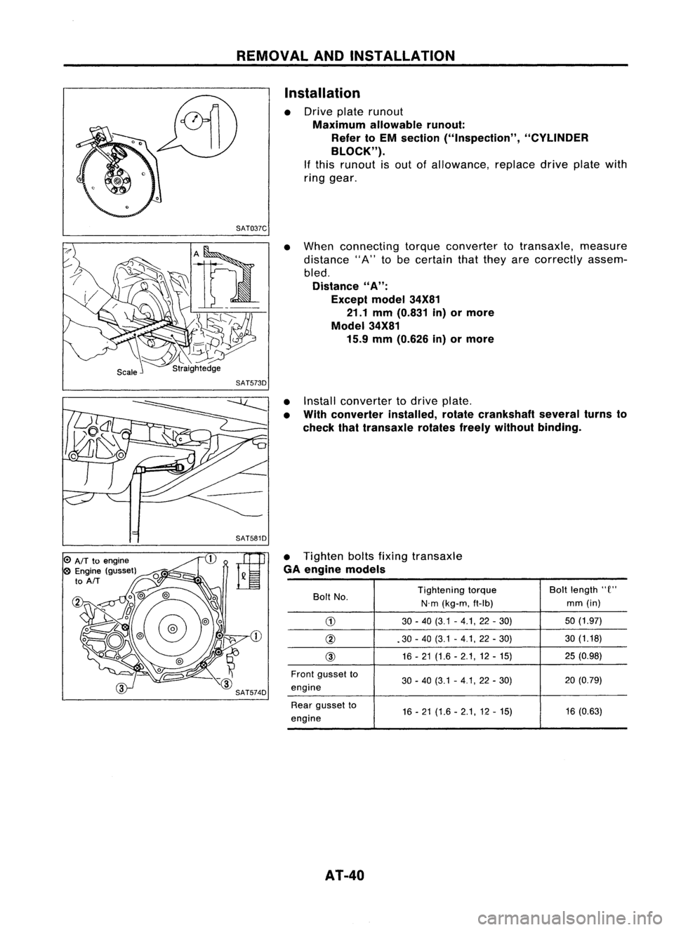
• Drive platerunout
Maximum allowablerunout:
Refer toEM section ("Inspection", "CYLINDER
BLOCK").
If this runout isout ofallowance, replacedriveplatewith
ring gear.
SAT037C
•When connecting torqueconverter totransaxle, measure
distance "A"tobe certain thatthey arecorrectly assem-
bled.
Distance
"A":
Except model34X81
21.1 mm(0.831 in)ormore
Model 34X81
15.9 mm(0.626 in)ormore
o
AIT
toengine
o
Engine (gusset)
to
AIT
SAT573D
•Install converter todrive plate.
• With converter installed,rotatecrankshaft severalturnsto
check thattransaxle rotatesfreelywithout binding.
• Tighten boltsfixing transaxle
GA engine models
Bolt No. Tightening
torque Boltlength
"e"
N.m (kg-m, ft-Ib) mm
(in)
G)
30-40 (3.1 -4.1,22 -30) 50
(1.97)
@ .30-40 (3.1 -4.1, 22-30) 30
(1.18)
@ 16
-21 (1.6 -2.1,12 -15) 25
(0.98)
Front gusset to
30-40 (3.1 -4.1,22 -30) 20
(0.79)
engine
Rear gusset to
16-21 (1.6 -2.1,12 -15) 16
(0.63)
engine
AT-40
Page 41 of 1701

Boltlength
'T'
mm (in)
55 (2.17)
50 (1.97)
65 (2.56)
25 (0.98)
40 (1.57)
Tightening
torque
N'm (kg-m, ft-Ib)
70 -79 (7.1 -8.1,51 -59)
70 -79 (7.1 -8.1, 51-59)
70 -79 (7.1 -8.1,51 -59)
30 -40 (3.1 -4.1, 22-30)
30 -40 (3.1 -4.1, 22-30)
CD
@
@
@
@
Bolt
No.
• Reinstall anypart removed.
• Adjust throttle wireandcontrol cable.Referto"ON-VEHI-
CLE SERVICE", AT-33,35.
•. Check inhibitor switch.Referto"Electrical Components
Inspection", AT-3D.
• Refill transaxle withATFandcheck fluidlevel, AT-17.
• Move selector leverthrough allpositions tobe sure that
transaxle operatescorrectly. Withparking brakeapplied,
idle engine. Moreselector leverthrough "N"to"D", to"2",
to "1" and "R". Aslight shock should befelt through the
hand gripping theselector eachtimethetransaxle is
shifted. •
• Perform roadtest-Refer to"ROAD TESTING", AT-17.
i
REMOVAL
ANDINSTAllATION
Installation (Cont'd)
SR engine models
SAT638A
SAT558DA
AIT
toengine
@
Engine to
AIT
AT-41
Page 115 of 1701
Rearinternal
gear
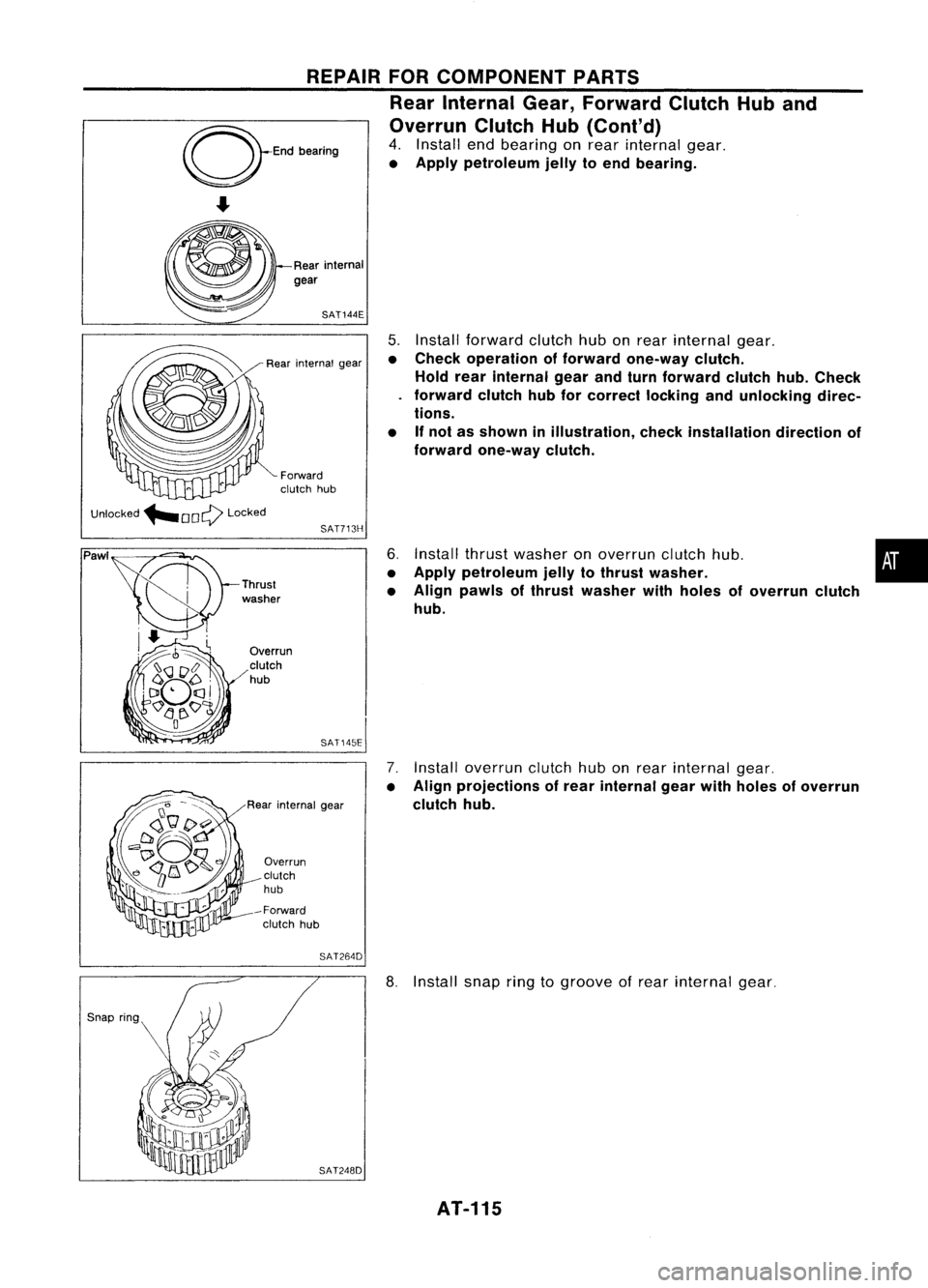
•
5.
Install forward clutchhubonrear internal gear.
• Check operation offorward one-way clutch.
Hold rearinternal gearandturn forward clutchhub.Check
forward clutchhubforcorrect lockingandunlocking direc-
tions.
• Ifnot asshown inillustration, checkinstallation directionof
forward one-way clutch.
6. Install thrustwasher onoverrun clutchhub.
• Apply petroleum jellytothrust washer.
• Align pawls ofthrust washer withholes ofoverrun clutch
hub.
7. Install overrun clutchhubonrear internal gear.
• Align projections ofrear internal gearwithholes ofoverrun
clutch hub.
SAT144E
REPAIR
FORCOMPONENT PARTS
Rear Internal Gear,Forward ClutchHuband
Overrun ClutchHub(Cont'd)
4. Install endbearing onrear internal gear.
• Apply petroleum jellytoend bearing.
SAT713H
Forward
clutch hub
Rear
internal gear
SAT145E
Overrun
clutch
hub
-Forward clutch hub
Overrun
clutch
hub
Rear internal gear
Unlocked
"'OOQ Locked
Pawl
SAT264D
SAT248D
8.
Install snapringtogroove ofrear internal gear.
AT-115
Page 140 of 1701
KV38105710
Transmission
case
NAT033
Reduction
pinion
gear
SAT332DA
D
SAT333DA ASSEMBLY
Adjustment 1(Cont'd)
9. Remove converter housingfromtransmission case.
10. Remove finaldrive assembly fromtransmission case.
11. Remove differential sidebearing outerracefrom transmis-
sion case.
12. Reinstall differential sidebearing outerraceandshim(s)
selected fromSDStable ontransmission case.
13. Reinstall converter housingontransmission caseand
tighten transmission casefixing boltstothe specified
torque.
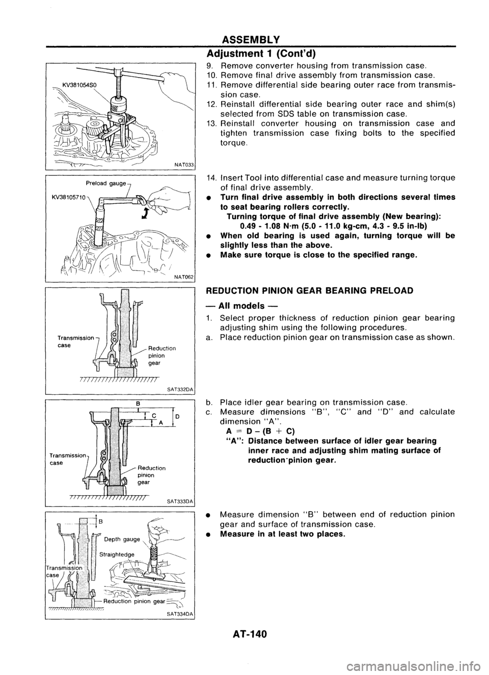
14. Insert Toolintodifferential caseandmeasure turningtorque
of final drive assembly.
• Turn finaldrive assembly inboth directions severaltimes
to seat bearing rollerscorrectly.
Turning torqueoffinal drive assembly (Newbearing):
0.49 -1.08 N'm(5.0-11.0 kg-em, 4.3-9.5 in-Ib)
• When oldbearing isused again, turning torquewillbe
slightly lessthan theabove.
• Make suretorque isclose tothe specified range.
REDUCTION PINIONGEARBEARING PRELOAD
- All models -
1. Select proper thickness ofreduction piniongearbearing
adjusting shimusing thefollowing procedures.
a. Place reduction piniongearontransmission caseasshown.
b. Place idlergear bearing ontransmission case.
c. Measure dimensions "8","C"and"D" andcalculate
dimension "A".
A
=
D-(8 +C)
"A":
Distance betweensurfaceofidler gear bearing
inner raceandadjusting shimmating surface of
reduction'pinion gear.
• Measure dimension "8"between endofreduction pinion
gear andsurface oftransmission case.
• Measure inat least twoplaces.
AT-140
Page 142 of 1701
~245 -275 N.m
(25 -28 kg-m, 181-203 ft-Ib)
SAT339D ASSEMBLY
Adjustment 1(Cont'd)
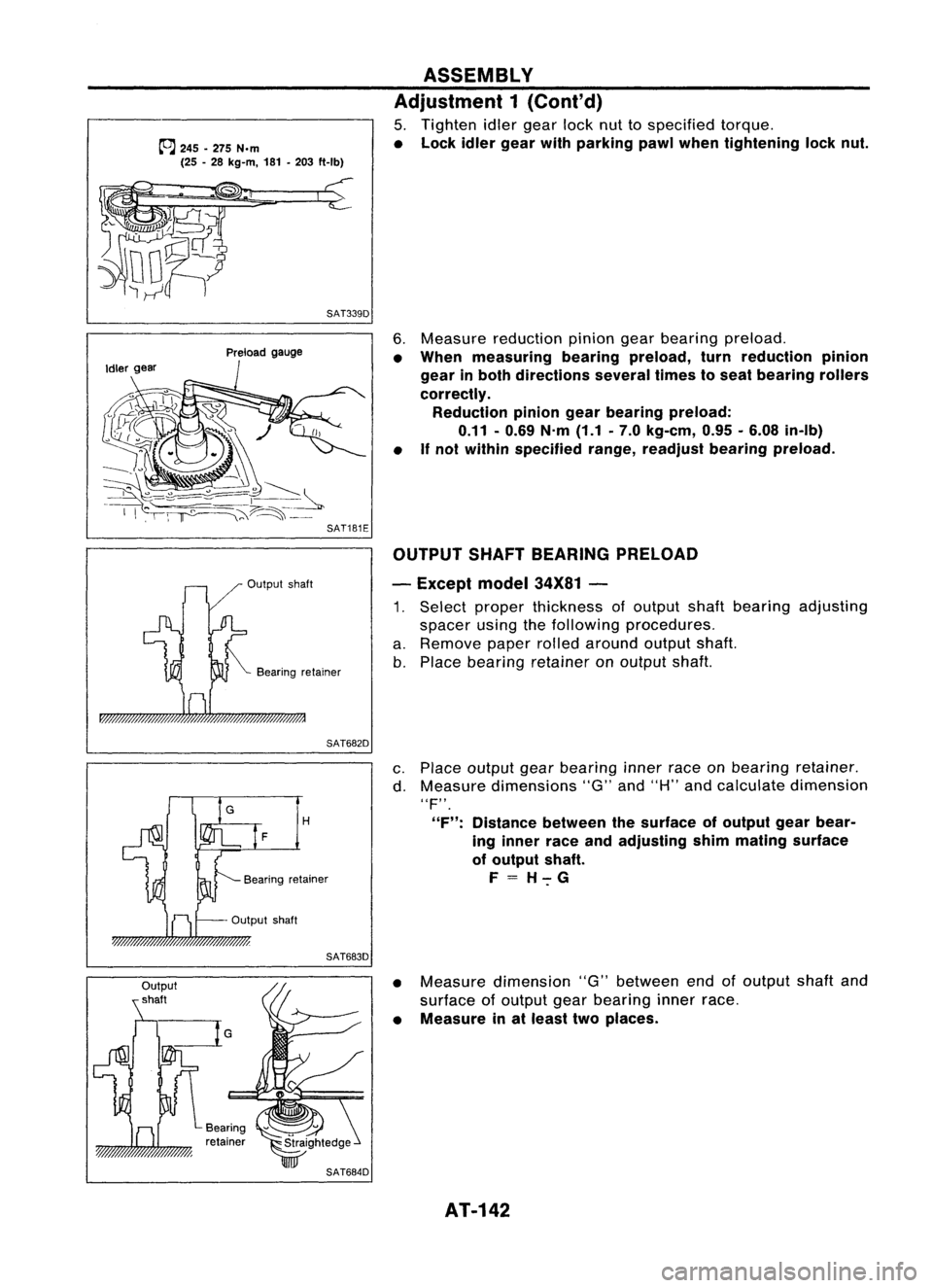
5. Tighten idlergear locknuttospecified torque.
• Lock idlergear withparking pawlwhen tightening locknut.
Output shaft
Preload
gauge
Bearing retainer
6.
Measure reduction piniongearbearing preload.
• When measuring bearingpreload, turnreduction pinion
gear inboth directions severaltimestoseat bearing rollers
correctly. Reduction piniongearbearing preload:
0.11 -0.69 N.m(1.1.7.0 kg-em, 0.95•6.08 in-Ib)
• If
not within specified range,readjust bearingpreload.
OUTPUT SHAFTBEARING PRELOAD
- Except model34X81-
1. Select proper thickness ofoutput shaftbearing adjusting
spacer usingthefollowing procedures.
a. Remove paperrolledaround outputshaft.
b. Place bearing retainer onoutput shaft.
SAT682D
H
F
Output shaft
SAT683D
c.
Place output gearbearing innerraceonbearing retainer.
d. Measure dimensions "G"and"H" andcalculate dimension
"F".
"F": Distance betweenthesurface ofoutput gearbear-
ing inner raceandadjusting shimmating surface
of output shaft.
F=H-:-G
• Measure dimension "G"between endofoutput shaftand
surface ofoutput gearbearing innerrace.
• Measure inat least twoplaces.
AT-142
Page 144 of 1701
SAT689DASSEMBLY
Adjustment 1(Cont'd)
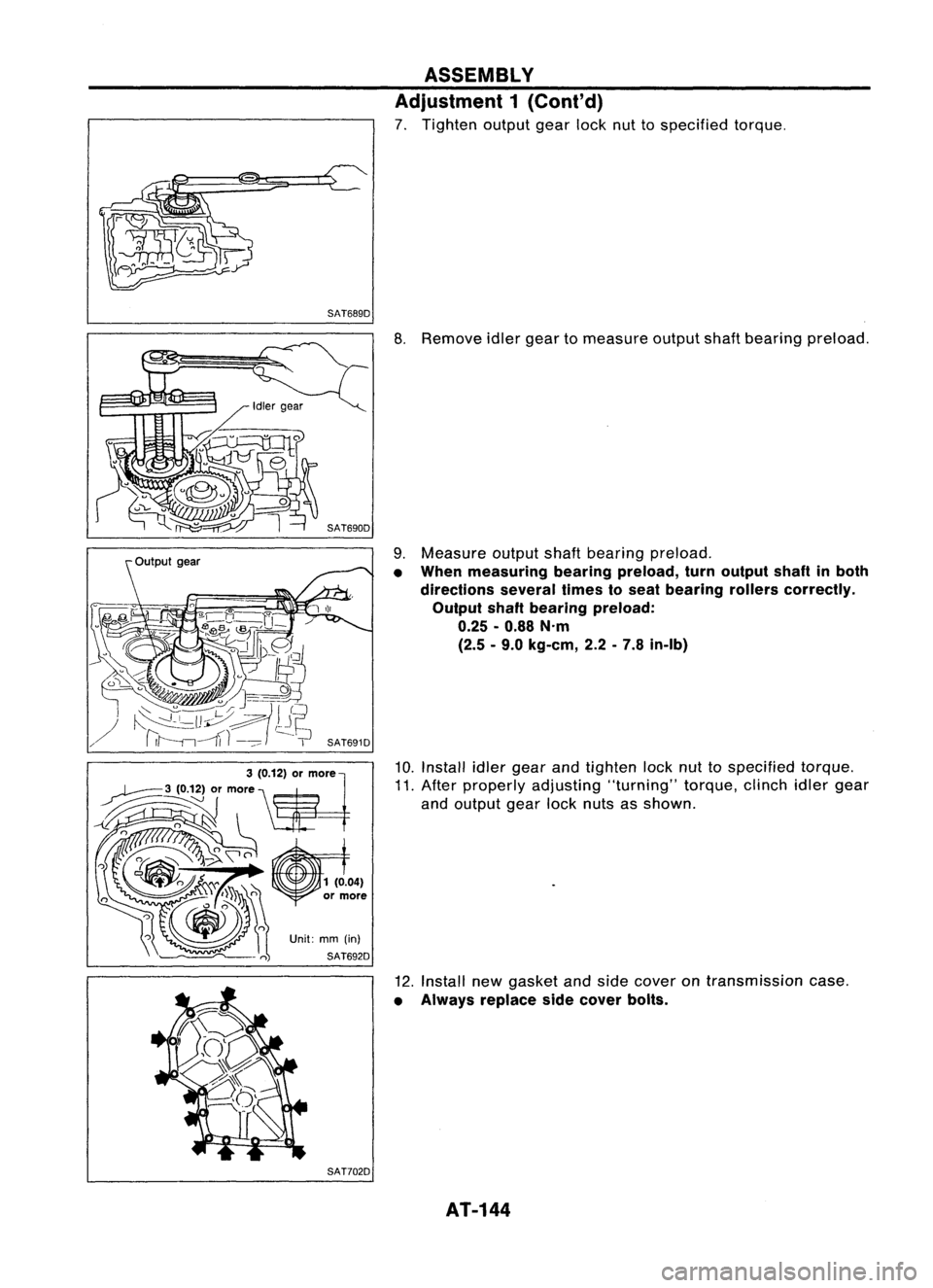
7. Tighten outputgearlocknuttospecified torque.
SAT702D
8.
Remove idlergear tomeasure outputshaftbearing preload.
9. Measure outputshaftbearing preload.
• When measuring bearingpreload, turnoutput shaftinboth
directions severaltimestoseat bearing rollerscorrectly.
Output shaftbearing preload:
0.25 -0.88 N'm
(2.5 -9.0 kg-em, 2.2-7.8 in-Ib)
10. Install idlergear andtighten locknuttospecified torque.
11. After properly adjusting "turning"torque,clinchidlergear
and output gearlocknuts asshown.
12. Install newgasket andside cover ontransmission case.
• Always replace sidecover bolts.
AT-144
Page 149 of 1701
Thrust
~.-b.. ~needle
~ bearing ASSEMBLY
Assembly 2(Cont'd)
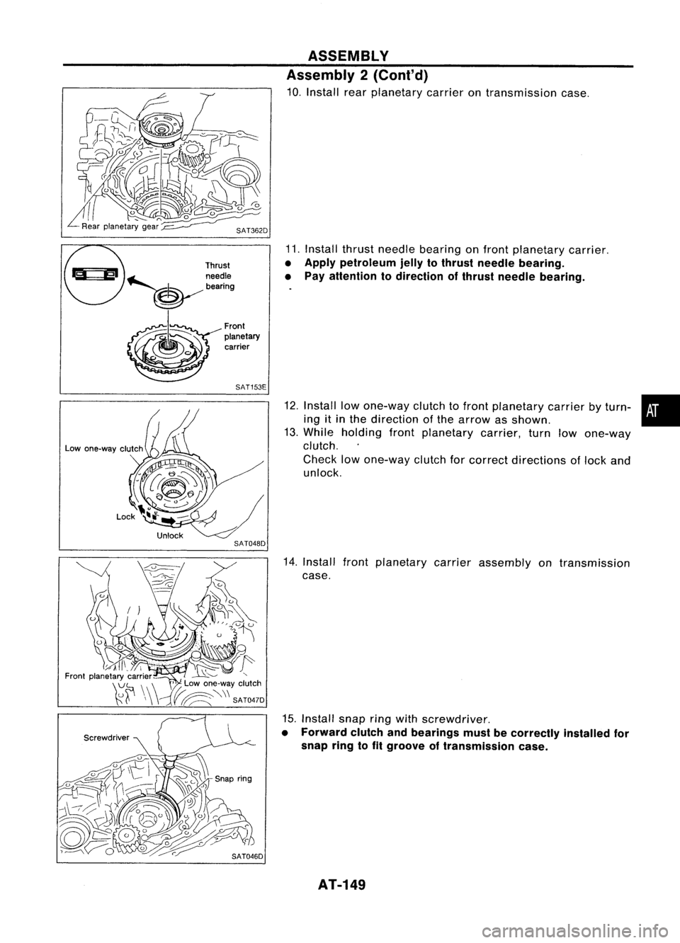
10. Install rearplanetary carrierontransmission case.
11. Install thrustneedle bearing onfront planetary carrier.
• Apply petroleum jellytothrust needle bearing.
• Pay attention todirection ofthrust needle bearing.
Front
planetary carrier
SAT153E
Screwdriver
12.
Install lowone-way clutchtofront planetary carrierbyturn- •
ing itin the direction ofthe arrow asshown.
13. While holding frontplanetary carrier,turnlowone-way
clutch.
Check lowone-way clutchforcorrect directions oflock and
unlock.
14. Install frontplanetary carrierassembly ontransmission
case.
15. Install snapringwith screwdriver.
• Forward clutchandbearings mustbecorrectly installedfor
snap ringtofit groove oftransmission case.
AT-149