1995 NISSAN ALMERA N15 Correct
[x] Cancel search: CorrectPage 473 of 1701
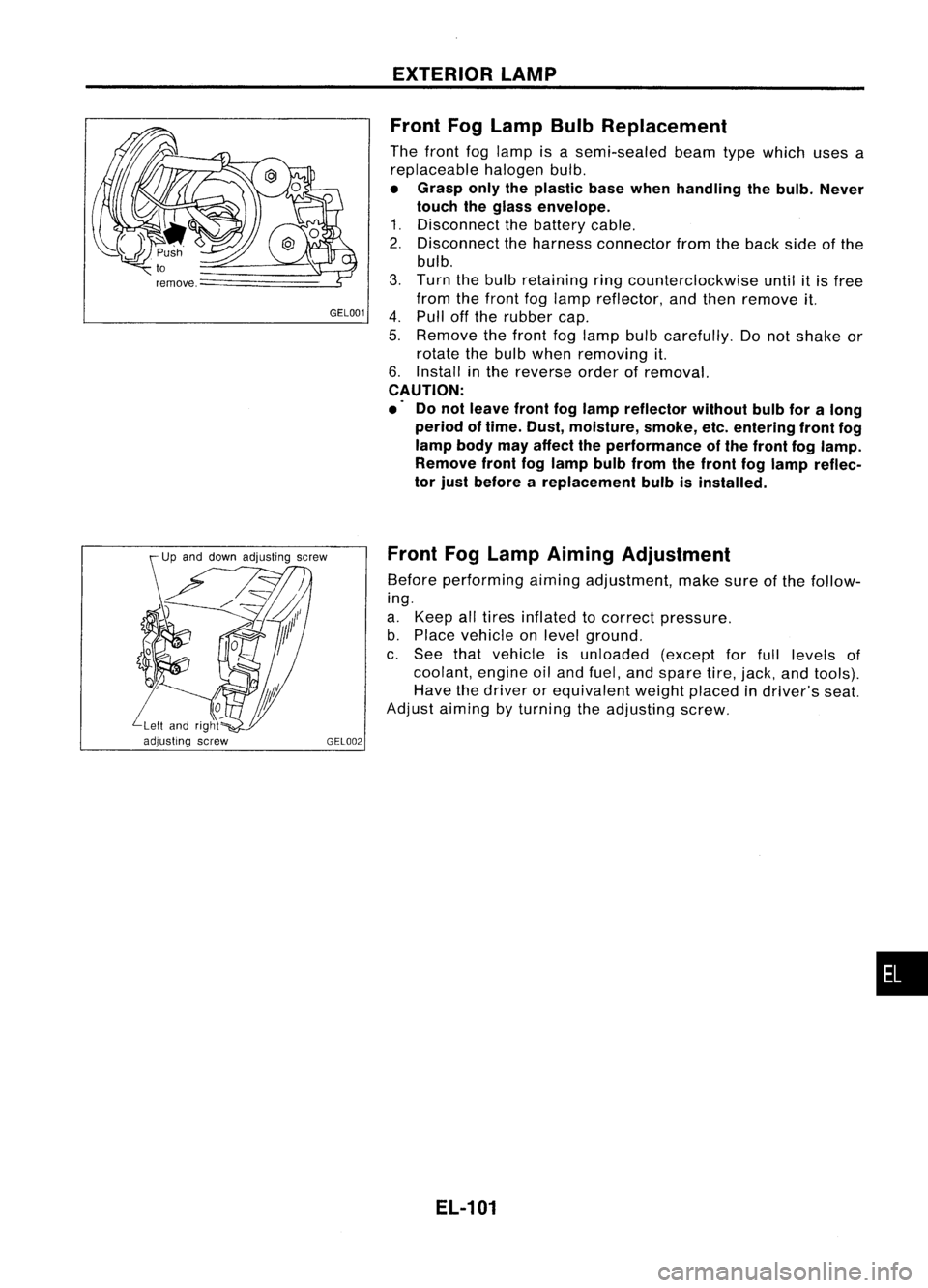
GEL001EXTERIOR
LAMP
Front FogLamp BulbReplacement
The front foglamp isasemi-sealed beamtypewhich usesa
replaceable halogenbulb.
• Grasp onlytheplastic basewhen handling thebulb. Never
touch theglass envelope.
1. Disconnect thebattery cable.
2. Disconnect theharness connector fromtheback sideofthe
bulb.
3. Turn thebulb retaining ringcounterclockwise untilitis free
from thefront foglamp reflector, andthen remove it.
4. Pull offthe rubber cap.
5. Remove thefront foglamp bulbcarefully. Donot shake or
rotate thebulb when removing it.
6. Install inthe reverse orderofremoval.
CAUTION:
.' Donot leave frontfoglamp reflector withoutbulbforalong
period oftime. Dust, moisture, smoke,etc.entering frontfog
lamp bodymayaffect theperformance ofthe front foglamp.
Remove frontfoglamp bulbfrom thefront foglamp reflec-
tor just before areplacement bulbisinstalled.
Front FogLamp Aiming Adjustment
Before performing aimingadjustment, makesureofthe follow-
ing.
a. Keep alltires inflated tocorrect pressure.
b. Place vehicle onlevel ground.
c. See thatvehicle isunloaded (exceptforfull levels of
coolant, engineoiland fuel, andspare tire,jack, andtools).
Have thedriver orequivalent weightplaced indriver's seat.
Adjust aiming byturning theadjusting screw.
EL-101
•
Page 708 of 1701
Front
Inside of
..-1'.
vehicle
L..y'
\
'
~Ud
Outside of
vehicle SFA508A
SFA957A
SFA625B FRONT
SUSPENSION
Coil Spring andStrut Assembly (Cont'd)
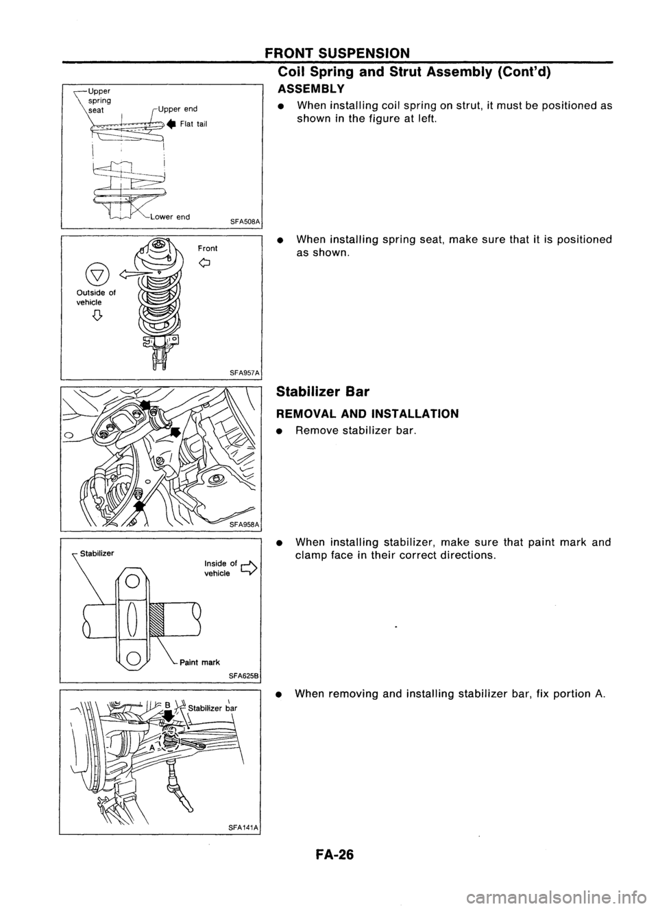
ASSEMBLY
• When installing coilspring onstrut, itmust bepositioned as
shown inthe figure atleft.
• When installing springseat,make surethatitis positioned
as shown.
Stabilizer Bar
REMOVAL ANDINSTALLATION
• Remove stabilizer bar.
• When installing stabilizer, makesurethatpaint markand
clamp faceintheir correct directions.
• When removing andinstalling stabilizer bar,fixportion
A.
FA-26
Page 726 of 1701
PRECAUTIONSANDPREPARATION
Supplemental RestraintSystem(SRS)"AIR
BAG" (DualAirBag System)
The Supplemental RestraintSystem"AirBag", usedalong withaseat belt,helps toreduce therisk or
severity ofinjury tothe driver andfront passenger inafrontal collision. TheSupplemental Restraint
System consists ofair bag modules (locatedinthe center ofthe steering wheelandonthe instrument
panel onthe passenger side),adiagnosis sensorunit,warning lamp,wiring harness andspiral cable.
Information necessarytoservice thesystem safelyisincluded inthe
RSsection
ofthis Service Manual.
WARNING:
• Toavoid rendering theSRS inoperative, whichcouldincrease therisk ofpersonal injuryordeath
in the event ofacollision whichwould resultinair bag inflation, allmaintenance mustbeperformed
by an authorized NISSANdealer. •
• Improper maintenance, includingincorrectremovalandinstallation ofthe SRS, canlead topersonal
injury caused byunintentional activationofthe system.
• Donot use electrical testequipment ~nany circuit related tothe SRS unless instructed tointhis
Service Manual. SRSwiring harnesses arecovered withyellow insulation eitherjustbefore the
harness connectors orfor the complete harness,foreasy identification.
Supplemental RestraintSystem(SRS)"AIR
BAG" (Single AirBag System)
The Supplemental RestraintSystem"AirBag", usedalong withaseat belt, helps toreduce therisk or
severity ofinjury tothe driver inafrontal collision. TheSupplemental RestraintSystemconsists ofan
air bag module (located inthe center ofthe steering wheel),adiagnosis sensorunit,warning lamp,
wiring harness andspiral cable. Information necessarytoservice thesystem safelyisincluded inthe
RS section
ofthis Service Manual.
WARNING: • Toavoid rendering theSRS inoperative, whichcouldincrease therisk ofpersonal injuryordeath
in the event ofacollision whichwould resultinair bag inflation, allmaintenance mustbeperformed
by an authorized NISSANdealer.
• Improper maintenance, includingincorrectremovalandinstallation ofthe SRS, canlead topersonal
injury caused byunintentional activationofthe system.
• Donot use electrical testequipment onany circuit related tothe SRS unless instructed tointhis
Service Manual.
EC-7
Page 771 of 1701
![NISSAN ALMERA N15 1995 Service Manual ON-BOARDDIAGNOSTIC SYSTEMDESCRIPTION
CONSULT (Coni'd)
Monitored item
ECM
Main
[Unit] input
signals Description
Remarks
signals
LOAD SIGNAL •Indicates [ON/OFF] conditionfromthe
[ON/OFF] reardefo NISSAN ALMERA N15 1995 Service Manual ON-BOARDDIAGNOSTIC SYSTEMDESCRIPTION
CONSULT (Coni'd)
Monitored item
ECM
Main
[Unit] input
signals Description
Remarks
signals
LOAD SIGNAL •Indicates [ON/OFF] conditionfromthe
[ON/OFF] reardefo](/manual-img/5/57349/w960_57349-770.png)
ON-BOARDDIAGNOSTIC SYSTEMDESCRIPTION
CONSULT (Coni'd)
Monitored item
ECM
Main
[Unit] input
signals Description
Remarks
signals
LOAD SIGNAL •Indicates [ON/OFF] conditionfromthe
[ON/OFF] reardefogger signaland/or lighting
switch.
0 0
ON:
Rear defogger isoperating
and/or lighting switchison.
OFF: Rear defogger isnot operating
and lighting switchisnot on.
INJ PULSE [msec]
0
•
Indicates theactual fuelinjection
•When theengine isstopped, acertain
pulse widthcompensated byECM computedvalueisindicated.
according tothe input signals.
IGN TIMING [BTDC]
0
•
Indicates theignition timingcomputed
by ECM according tothe input sig-
nals.
IACV-AACIV
[%]
•Indicates theidle aircontrol valve
0
(AAC
valve) control valuecomputed
by ECM according tothe input sig-
nals.
A/F ALPHA
[%]
•Indicates themean valueofthe air-
•When theengine isstopped, acertain
0
fuel
ratio feedback correction factor valueisindicated.
per cycle. •This data alsoincludes thedata for
the air-fuel ratiolearning control.
AIR COND RLY
0
•
Indicates theairconditioner relay
[ON/OFF] controlcondition (determined byECM
according tothe input signal).
COOLING FAN*2
•Indicates thecontrol condition ofthe
[ON/OFF] or[LOW/
coolingfans(determined byECM
HI/OFF]
0
according
tothe input signal).
ON ...Operating
LOW ...Operates atlow speed
HI ...Operates athigh speed
OFF ...Stopped
FUEL PUMP RLY
0
•
Indicates thefuel pump relaycontrol
[ON/OFF] conditiondetermined byECM accord-
ing tothe input signals.
VALVE TIMSOL*1
•The control condition ofthe valve tim-
[ON/OFF] ingsolenoid valve(determined by
ECM according tothe input signal) is
indicated.
ON ...VTC operating
OFF ...VTC notoperating
EGRC SOLIV (EVAP
•Indicates thecontrol condition ofthe
canister purgecon-
EVAPcanister purgecontrol solenoid
trol solenoid valve valveorEGR valve
&
EVAP canister
or EGR
&
EVAP can- purgecontrol solenoid valve(deter-
ister purge control
0
mined
byECM according tothe input
solenoid valve) signal).
[ON/OFF] ON'"EVAP canister purgeoperation
cut-off OFF ...EVAP canister purgeoperation
not cut-off
VOLTAGE •Voltage measured bythe voltage
[V] probe.
PULSE •Pulse width, frequency orduty cycle •Only "#"isdisplayed ifitem is
[msec] or[Hz] or measuredbythe pulse probe. unable
tobe measured .
[%]
•
Figures with"#"s aretemporary
ones. Theyarethesame figures as
an actual pieceofdata which wasjust
previously measured.
*1: GA16DE exceptforEurope andIsrael
*2: GA16DE engineA/Tmodels forEurope without heavydutykithave a2- step control [ON/OFF] system."LOW"and"HI"
are shown onCONSULT screentorepresent "ON"condition.
EC-52
Page 790 of 1701
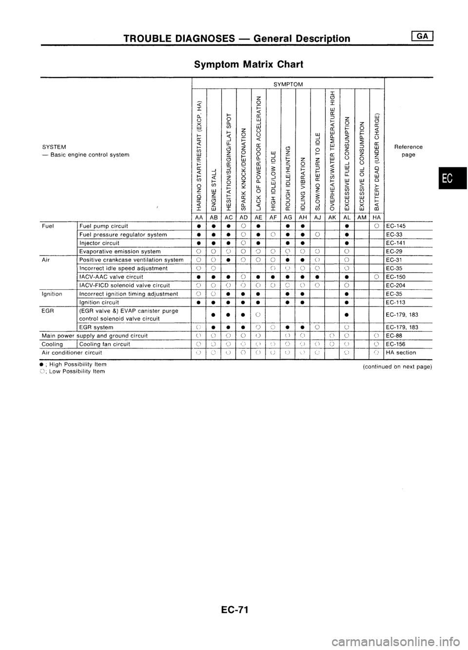
TROUBLEDIAGNOSES -General Description
Symptom MatrixChart
SYMPTOM
:c
z
(!l
~
0
I
:c
i=
w
cL
~
<{
0::
0::
='
W
<.)
0
w
~
z
CJ
x
Cl.
-I
0
Z
0::
~
en
w
i=
0
z
<.)
0::
<{
~
0
<.)
w
w
Cl.
i=
:c
~
-I
Cl.
::?
Cl.
<.)
0::
-I
i=
<{
Q
::?
=' ::?
<{
u..
<{
0::
SYSTEM
0::
W
en
='
Reterence
~
0
CJ
0
~
z
w
en
0
w
z
0
en
0
- Basic engine control system
w
z
0
~
0::
Z
Z
page
0::
<3
~
Cl.
-I
i=
w
<.)
0
w
Q
z
z
2-
j:::
0::
0
ii
z
0
0::
~
-I
<.)
0::
='
;;:
w
:s:
='
i=
='
<{
W
-I
0
<{
-I
en
:s:
:c
~
:s:
='
6
<{
-I
Z
<.)
0
w
<{
w
en
u..
w
~
<{
00
-I
0::
en
~
Cl.
W
-I
III
0::
~
W
W
0
0
en
0
z
Q
:;
0
<{
> >
i=
~
LL
-I
>-
Z
W
0
Q
z
w
U5 U5
0::
2i
z
<{
~ :c
(!l
~:c
en en
w
<3
~
0::
~
:c
CJ
z
0::
W W
~
0::
U5
<{
<.)
CJ
='
:J
0
w
<.)
<.)
~
I
<{
Z
W
Cl.
<{
0
Q
-I
>
X
X
<{
:c
w
:c
en
-I
:c
0::
en
0
w
W
III
AA AB AC ADAEAFAG
AH AJ
AK AL
AM HA
Fuel Fuel
pump circuit
••
•
0
•
•
•
•
0
EC-145
Fuel pressure regulator system
•••
0
•
0
•
•
0
•
EC-33
Injector circuit
•• •
0
• •
• •
EC-141
Evaporative emissionsystem
00
[)
00
()
0
0 0 0
EC-29
Air Positivecrankcase ventilation system
00
•
0
0
0
••
U
()
EC-31
Incorrect idlespeed adjustment
0
0
()
(~)
C)
0 0
EC-35
IACV-AAC valvecircuit
•••
(,
••• •• •
0
EC-150
~)
IACV-FICD solenoidvalvecircuit
C)
()
()
()
0
C)
(~,
()
0
0
EC-204
Ignition Incorrectignitiontimingadjustment
0
0
•• •
•
• •
EC-35
Ignition circuit
••
•
•
• •
•
•
EC-113
EGR (EGRvalve
&)
EVAP canister purge
0
EC-179,183
control soienoid valvecircuit
••
• •
EGR system
U
••
•
r)
(,)
•
•
0
0
EC-179.
183
Main power supply andground circuit
()
() ()
0 0
()
Ci
()
0
(
~
EC-88
Cooling
I
Cooling tancircuit
()
:.'-1
U
()
(,)
',)
C)
t)
U
n
(J
0
EC-156
u
Air conditioner circuit
()
Co
u
()
CJ
UU
"
,
C:
~,
()
HAsection
•
• ;High Possibility Item
(), Low Possibility Item
EC-71
(continued
onnext page)
Page 791 of 1701
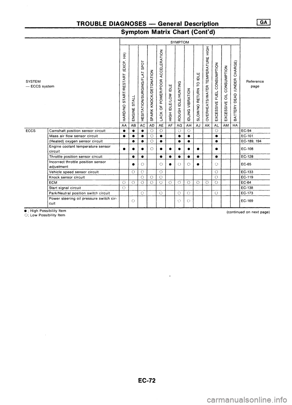
TROUBLEDIAGNOSES -General Description
Symptom MatrixChart(Cont'd)
SYMPTOM
:I:
Z
C)
~
0
I
:I:
i=
UJ
c.:
I-
«
a:
[ij'
a:
:J
u
0
UJ
I-
Z
C)
X
ll.
--l
«
0
z
a:
~
(f)
UJ
a:i=
0
«
I-
z
U
UJ
ll.
i=
:I:
I-
«
0
u
UJ
ll.
:2
ll.
U
a:
--l
i=
«
--l
:2
9
:J
:2
«
u.
«
a:
UJ
(f)
a:
SYSTEM
I-
a
z
:J
UJ
Reference
(f)
0
C)
0
I-
Z
(f)
Cl
- ECCS system
UJ
z
0
0
w
Z
I-
a:
0
z
z
page
a:
c;
l-
ll.
--l
i=
w
u
0
UJ
9
z
z
2-
i==:
a:
Cl
ii:
z
0
a:
I-
--l
U
a::
:J
l2
UJ
~
:J
i=
:J
«
UJ
--l
Cl
«
--l
(f)
~
:I:
I-
~
:J
(5
«
I-
--l
Z
U
0
UJ
«
UJ
en
u.
UJ
«
00
--l
a::
(f)
l-
ll.
W
--l
[])
a::
I-
w
W
Cl
0
(f)
0
z
9
;;
0
«
>
>
>-
i=
::.::
u.
--l
Z
0
9
z
UJ
in in
a::
UJ
«
:I:
:I:
a
z
I-
::.::
C)C)
~
(f)
(f)
UJ
a::
::.::
:I:
z
a::
UJ UJ
I-
a::
c;
in
«
u
C)
:J
:J
0
UJ
U U
I-
«
z
UJ
ll.
«
i
0
9
--l
>
X X
«
:I:
w
:I:(f)
--l
a::
(f)
0
UJ UJ
[])
AA ASAC AD AEAFAG AH AJAK ALAM HA
ECCS Camshaft
positionsensorcircuit
•••
0
0
()
0 0
EC-94
Mass airflow sensor circuit
••
•
0
•
••
•
EC-101
(Heated) oxygensensorcircuit
••
0
• •
•
•
EC-189,194
Engine coolant temperature sensor
••
•
0
••
•
•
•
•
EC-108
circuit
Throttle position sensorcircuit
•• ••• ••
•
EC-128
Incorrect throttleposition sensor
•
()
()
•
0
0
•
()
EC-65
adjustment
Vehicle speedsensor circuit
0
C)
()
0
EC-133
Knock sensor circuit
000 0
EC-119
ECM
0
()
0 0
()
0
()
()()
0 0
EC-64
Start signal circuit
0
EC-138
Park/Neutral positionswitchcircuit
0
0
0
0
0
EC-173
Power steering oilpressure switchcir-
0
(J
0
EC-169
cuit
• ;High Possibility Item
0;
Low Possibility Item
EC-72
(continued
onnext page)
Page 977 of 1701
![NISSAN ALMERA N15 1995 Service Manual ON-BOARDDIAGNOSTIC SYSTEMDESCRIPTION
CONSULT (Conl'd)
Monitored item ECM
Main
[Unit] input
signals Description
Remarks
signals
AIR COND SIG •Indicates [ON/OFF] conditionofthe
[ON/OFF]
00
air
NISSAN ALMERA N15 1995 Service Manual ON-BOARDDIAGNOSTIC SYSTEMDESCRIPTION
CONSULT (Conl'd)
Monitored item ECM
Main
[Unit] input
signals Description
Remarks
signals
AIR COND SIG •Indicates [ON/OFF] conditionofthe
[ON/OFF]
00
air](/manual-img/5/57349/w960_57349-976.png)
ON-BOARDDIAGNOSTIC SYSTEMDESCRIPTION
CONSULT (Conl'd)
Monitored item ECM
Main
[Unit] input
signals Description
Remarks
signals
AIR COND SIG •Indicates [ON/OFF] conditionofthe
[ON/OFF]
00
air
conditioner switchasdetermined
by the airconditioning signal.
PIN POSI SW
00
•
Indicates [ON/OFF] conditionfromthe
[ON/OFF] park/neutralpositionswitchsignal.
PW/ST SIGNAL •Indicates [ON/OFF] conditionofthe
[ON/OFF]
00
power
steering oilpressure switch
determined bythe power steering oil
pressure signal.
INJ PULSE [msec]
0
•
Indicates theactual fuelinjection •
When theengine isstopped, acertain
pulse widthcompensated byECM computedvalueisindicated.
according tothe input signals.
IGN TIMING [BTDC]
0
•
Indicates theignition timingcomputed
by ECM according tothe input sig-
nals.
IACV-AACIV
[%]
•Indicates theidle aircontrol valve
0
(AAC
valve) control valuecomputed
by ECM according tothe input sig-
nals.
A/F ALPHA [%J •Indicates themean valueofthe air- •When theengine isstopped, acertain
0
fuel
ratio feedback correction factor valueisindicated.
per cycle. •This dataalsoincludes thedata for
the air-fuel ratiolearning control.
AIR COND RLY •Indicates theairconditioner relay
[ON/OFF]
0
control
condition (determined byECM
according tothe input signal).
FUEL PUMP RLY •Indicates thefuel pump relaycontrol
[ON/OFFJ
0
condition
determined byECM accord-
ing tothe input signals.
COOLING FAN
•Indicates thecontrol condition ofthe
[HI/LOW/OFFJ coolingfans(determined byECM
0
according
tothe input signal).
HI ...High speed operation
LOW ...Low speed operation
OFF ...Stopped
EGRC SOLIV •Indicates thecontrol condition ofthe
[ON/OFFJ EGR
valve
&
EVAP canister Purge
control solenoid valve(determined by
0
ECM
according tothe input signal).
ON ...EGR andEVAP canister purge
operation cut-off
OFF ...EGR andEVAP canister purge
operation notcut-off
VOLTAGE •Voltage measured bythe voltage
[V] probe.
PULSE •Pulse width, frequency orduty cycle •Only "#"isdisplayed ifitem is
[msec] or[Hz] or
measuredbythe pulse probe. unabletobe measured.
[%]
•Figures with"#"s aretemporary
ones. Theyarethesame figures as
an actual pieceofdata which wasjust
previously measured.
EC-258
Page 993 of 1701
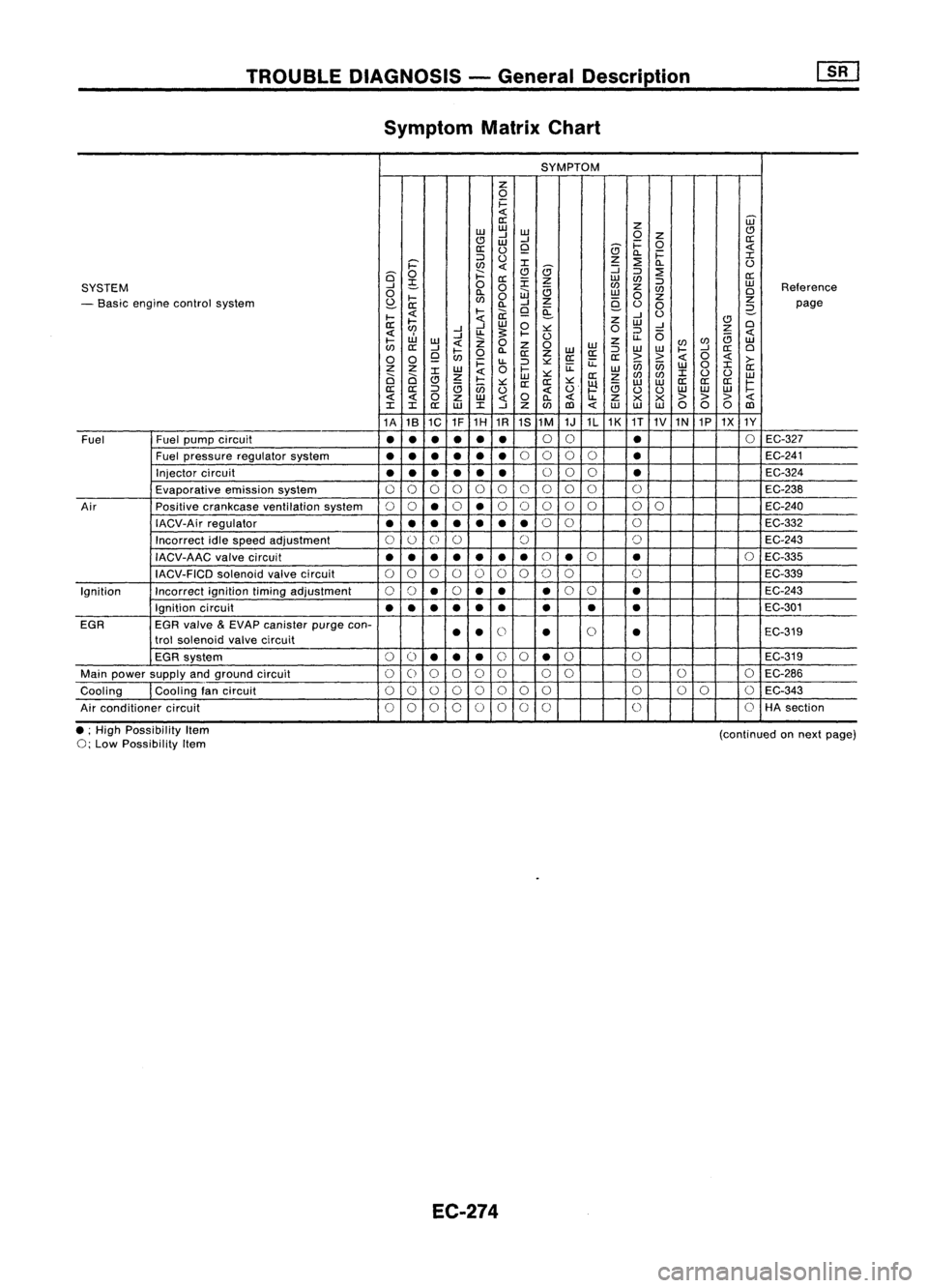
TROUBLEDIAGNOSIS -General Description
Symptom MatrixChart
SYMPTOM
z
0
i=
0::
Z
ill
w w
w
(!)
(!J
-l
-l
0
Z
0::
W
i=
0
0::
0
Q
(9
c..
i=
::>
0
z
::2:
:r:
i='
l/)
(9
:J
c..
0
6'
0
j::::
Q
::>
::2:
0::
;S
0
0::
:r:
z
w
l/)
::>
w
SYSTEM
....J
0
a
l/)
z
l/)
Reference
0
l-
e..
0
iJJ
w
0
z
0
- Basic engine control system
S?-
l/)
-l
Z
9-
z
0::
c..
Q ~
0
0
2-
page
I-
l-
ii:
....J
0
II:
I-
w
0
z
w
(!)
0
l/)
....J....J
~
:>:::
0
::>
-l
z
uJ
....J
U.
I-
0
U.
(5
B
I-
W
0
z
l/)
w
l/)
II:
....J
Z
0
W
WW
l/)
....J
II:
0
I-
0
c..
II:
Z
W
II:
::>
I-
0
0
Q
l/)
II:II:
>>
i=
u.
::>
:>:::
u::
ii5ii5
w
0
:r:
>-
z z
w
0
I-
u::
W
II:
0 0
:r:
z
w
:>:::
II:
z
l/)
l/)
:r:
0 0
w
(!J
I-
:>:::
II: II:
:>:::
~
w
W
II:
II: II:
r:
II:
II:
::>
B
ii5
0
B
00
w
w w
z
w
c..
Z
><><
>
> >
:r: :r:
II:
w
:r:
-l
z
l/)
co
WW
00 0
co
1A 181C 1F1H
1R
1S1M
1J1L1K
1T
1V1N 1P1X 1Y
Fuel Fuelpump circuit
•
•
•
•
•
•
0
0
•
0
EC-327
Fuel pressure regulatorsystem
•
••
•
••
0
0 00
•
EC-241
Injector circuit
••
•
• •
•
0
00
•
EC-324
Evaporative emissionsystem
00 0 00
0 0
0
0
0 0
EC-238
Air Positivecrankcase ventilation system
00
•
0
•
0
0 0
0
0
00
EC-240
IACV-Air regulator
•••
•
••
•
0
0
0
EC-332
Incorrect idlespeed adjustment
0
0
0
0 0 0
EC-243
IACV-AAC valvecircuit
••
•
•
•
•
•
0
•
0
•
0
EC-335
IACV-FICD solenoidvalvecircuit
0
0 0
000 00 0
C)
EC-339
Ignition Incorrectignitiontimingadjustment
00
•
0
•• •
0
0
•
EC-243
Ignition circuit
•
•
•
•
•
•
• •
•
EC-301
EGR EGRvalve
&
EVAP canister purgecon-
00
trol solenoid valvecircuit
•
•
•
•
EC-319
EGR system
0
()
•• •
0
0
•
0
0
EC-319
Main power supply andground circuit
00 0 0
C)
0 00
0
0
0
EC-286
Cooling Coolingfancircuit
0
0
0
00 00 0 000 0
EC-343
Air conditioner circuit
00 00 0
00
0 0
0
HA
section
• ;High Possibility Item
0;
Low Possibility Item
EC-274
(continued
onnext page)