Page 1295 of 1701
COMPRESSIONPRESSURE
6. Fitcompression gaugetocylinder head.
SEM505D
7.Crank engine andread compression gaugeindication.
Cranking speed:200rpm
Compression pressure:kPa(bar, kg/cm
2,
psi)
Standard
3,138 (31.4, 32,455)
Limit
2,452 (24.5, 25,356)
Limit ofdifference betweencylinders
490 (4.9, 5,71)
8. Ifthe pressure appearslow,pour about 3me (0.11 Impfloz)
of engine oilthrough nozzleholesandrepeat test.
For indications oftest, refer tothe following table.
Gauge indication duringtests Trouble
diagnosis
First
reading Second
reading
Increased
reading
Same reading
maintained
•
Piston ringsareworn ordamaged.
• Iftwo adjacent cylinders arelow, gasket isdamaged .
• Valve issticking .
• Valve seatorvalve contact surface isincorrect.
EM-116
Page 1302 of 1701
SEM558
SEM517D
SEM518D TIMING
BELT
[f[]
Camshaft TimingBelt(Cont'd)
Belt tensioner, tensionerspringandidler
1. Check belttensioner andidler forsmooth turning.
2. Check condition oftensioner spring.
Crankshaft sprocketandfront camshaft sprocket
Check teethforabnormal signs.
INSTALLATION
1. Install crankshaft sprocketplateincorrect direction.
2. Confirm thatNO.1 piston isset atTDC onitscompression
stroke. (TDCisindicated bycrankshaft pulleynotchwithout
painted mark.)
3. Install tensioner andreturn spring.
Temporarily tightenboltssothat tensioner isset atthe fully
outside position.
4. Install idlerandtighten bolttothe specified torque.
EM-123
•
Page 1305 of 1701

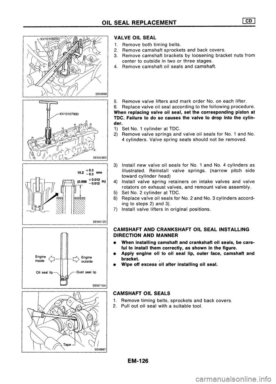
OILSEAL REPLACEMENT
Install newvalve oilseals forNo.1 andNO.4 cylinders as
illustrated. Reinstallvalvesprings. (narrowpitchside
toward cylinder head)
Install valvespring retainers onintake valves andvalve
rotators onexhaust valves,andremount valveassembly.
Set NO.2 cylinder at
TOG.
Replace valveoilseals forNo.2 andNo.3 cylinders accord-
ing tosteps 2)and 3).
Install valvelifters inoriginal positions.
5.
Remove valveliftersandmark order No.oneach lifter.
6. Replace valveoilseal according tothe following procedure.
When replacing valveallseal, setthe corresponding pistonat
TOe. Failure todo socauses thevalve todrop intothecylin-
der.
1) Set NO.1 cylinder at
TOG.
2) Remove valvesprings andvalve oilseals forNO.1 andNo.
4 cylinders. Valvespring seatsshould notberemoved.
VALVE
OilSEAL
1. Remove bothtiming belts.
2. Remove camshaft sprockets andback covers.
3. Remove camshaft bracketsbyloosening bracketnutsfrom
center tooutside intwo orthree stages.
4. Remove camshaft oilseals andcamshaft.
3)
+0.3
15.2 -0.3
mm
(0598
+0.012
In)
4)
. -0.012
5)
6)
~ 7)
SEM512D
Engine
/'t
inside
Y
r-l'\.
Engine
LV outside CAMSHAFT
ANDCRANKSHAFT OilSEAL INSTALLING
DIRECTION ANDMANNER
• When installing camshaftandcrankshaft oilseals, becare-
ful toinstall themcorrectly, asshown inthe figure.
• Apply engine oiltooil seal lip,outer face,camshaft and
bracket. .
• Wipe offexcess allafter installing oilseal.
Oil seal lip Dust
seallip
SEM715A CAMSHAFT OilSEALS
1. Remove timingbelts,sprockets andback covers.
2. Pull outoilseal withasuitable tool.
EM-126
Page 1310 of 1701
NGNG
SEM722BA CYLINDER
HEAD
[]Q]
Inspection (Cont'd)
VALVE GUIDEREPLACEMENT
1. Heat cylinder headinoil to150 to160°C (302to320°F).
2. Drive outvalve guide usingapress orhammer andasuit-
able tool.
3. Ream cylinder headvalve guide bore.
Reaming bore(service part):
11.185.11.196 mm(0.4404 .0.4408 in)
4. Heat cylinder headto150 to160°C (302to320°F) andpress
service valveguide ontocylinder head.
5. Ream valveguide.
Final size:
7.000 .7.015 mm(0.2756 .0.2762 in)
VALVE SEATS
1. Check valveandvalve seatforcontact.
Coat thevalve facewithprussian redlead.
If
contact is
wrong, correct valveseat.Ifthe valve redlead appears 360°
around face,thevalve stemandface areconcentric. Ifnot,
repair orreplace valve.
2. Check valveseats forpitting atcontact surface. Resurface
or replace ifexcessively worn.
Correct valveseatsurface.
When repairing valveseat,check valveandvalve guide for
wear beforehand. Ifworn, replace them.Thencorrect valve
seat.
EM-131
•
Page 1311 of 1701
![NISSAN ALMERA N15 1995 Service Manual
I
Recess
I
diameter
W: Refer toSOS.
I
SEM795A
SEMB76
SEM877
SEM635AA CYLINDER
HEAD
[£Q]
Inspection (Cont'd)
VALVE SEATREPLACEMENT
1. Bore outoldseat untilitcollapses.
Set machine depthst NISSAN ALMERA N15 1995 Service Manual
I
Recess
I
diameter
W: Refer toSOS.
I
SEM795A
SEMB76
SEM877
SEM635AA CYLINDER
HEAD
[£Q]
Inspection (Cont'd)
VALVE SEATREPLACEMENT
1. Bore outoldseat untilitcollapses.
Set machine depthst](/manual-img/5/57349/w960_57349-1310.png)
I
Recess
I
diameter
W: Refer toSOS.
I
SEM795A
SEMB76
SEM877
SEM635AA CYLINDER
HEAD
[£Q]
Inspection (Cont'd)
VALVE SEATREPLACEMENT
1. Bore outoldseat untilitcollapses.
Set machine depthstopsothat boring cannot contact bot-
tom face ofseat recess incylinder head.
2. Ream thecylinder headrecess.
Reaming boreforservice valveseat
[Oversize 0.5mm (0.020 in)]:
Intake 41.432 -41.454 mm(1.6312 -1.6320 in)
Exhaust 35.432-35.454 mm(1.3950 -1.3958 in)
Use thevalve gUide center forreaming toensure valveseatwill
have thecorrect fit.
3. Heat cylinder headtoatemperature of150 to160°C (302to
320°F) andpress fitseat untilitseats onthe bottom.
4. Install valveseats.
When replacing valveseat,valve should bereplaced aswell.
5. Cut orgrind valve seatusing asuitable toolatthe specified
dimensions asshown inSOS (EM-172).
The cutting shouldbedone withboth hands toobtain auniform
and concentric finish.
6. Apply asmall amount offine grinding compound tothe
valve's contacting faceandputthe valve intoitsguide.
Lap valve against itsseat untilproper valveseating is
obtained.
7. Check valveseating condition.
EM-132
Page 1312 of 1701
T(Margin thickness)
II
~a
.
,
I
T(Th)
D
L
CYLINDER
HEAD @Q]
Inspection (Cont'd)
VALVE DIMENSIONS
1. Check dimensions ofeach valve. Fordimensions, referto
SDS (EM-171).
2. Correct orreplace anyvalve thatisfaulty .
d •
L-~
SEM188A
3.Valve faceorvalve stemendsurface shouldberefaced by
using avalve grinder.
When valveheadhasbeen worn down to0.5 mm (0.020 in)in
margin thickness, replacethevalve.
Grinding allowance torvalve stemtipis0.5 mm (0.020 in)or
less.
VALVE SPRING SQUARENESS
Check valvespring forsquareness usingasteel square andflat
surface plate.
If
spring isout ofsquare "S"more thanspecified limit,replace
with newone.
Out-at-square: OuterLess than2.1mm (0.083 in)
Inner less than1.9mm (0.075 in)
•
SEM333
VALVE SPRING PRESSURE LOAD
Measure thefree length andthetension ofeach spring. Ifthe
measured valueexceeds thespecified limit,replace spring.
Refer toSDS (EM-172).
EM113 HYDRAULIC VALVELIFTER
1. Check contact andsliding surfaces forwear orscratches .
SEM7238 EM-133
Page 1314 of 1701

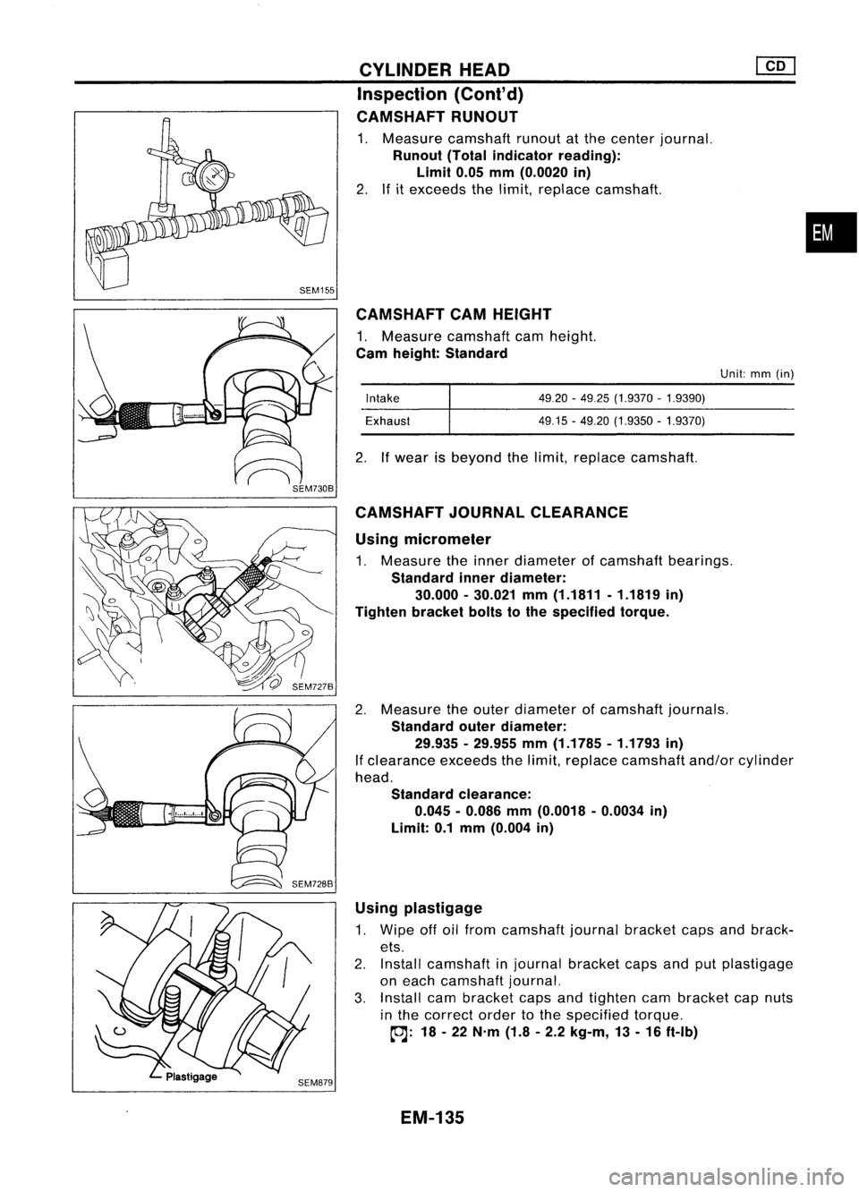
CAMSHAFTCAMHEIGHT
1. Measure camshaft camheight.
Cam height: Standard
Using micrometer
1. Measure theinner diameter ofcamshaft bearings.
Standard innerdiameter:
30.000 -30.021 mm(1.1811 -1.1819 in)
Tighten bracketboltstothe specified torque.
2. Measure theouter diameter ofcamshaft journals.
Standard outerdiameter:
29.935 -29.955 mm(1.1785 -1.1793 in)
If clearance exceedsthelimit, replace camshaft and/orcylinder
head.
Standard clearance:
0.045 -0.086 mm(0.0018 -0.0034 in)
Limit: 0.1mm (0.004 in)
•
Unit: mm(in)
49.20 -4925 (1.9370 -1.9390)
49.15 -49.20 (1.9350 -1.9370)
Intake
Exhaust
2. Ifwear isbeyond thelimit, replace camshaft.
CYLINDER
HEAD
Inspection (Cont'd)
CAMSHAFT RUNOUT
1. Measure camshaft runoutatthe center journal.
Runout (Totalindicator reading):
Limit 0.05mm(0.0020 in)
2. Ifitexceeds thelimit, replace camshaft.
CAMSHAFT JOURNALCLEARANCE
Using plastigage
1. Wipe offoilfrom camshaft journalbracket capsandbrack-
ets.
2. Install camshaft injournal bracket capsandputplastigage
on each camshaft journal.
3. Install cambracket capsandtighten cambracket capnuts
in the correct ordertothe specified torque.
~: 18-22 N'm (1.8-2.2 kg-m, 13-16 ft-Ib)
EM-135
Page 1328 of 1701
AB
Taper:A-B
Out-ot-round: X-y
y
SEM316A CYLINDER
BLOCK
Inspection (Cont'd)
Bearing replacement
1. Remove bearingwithasuitable tool.
Do not scratch innersurface ofconnecting rod.
2. Install newbearing withoilholes aligned correctly.
3. Ream boreusing asuitable tool.
Ream bore:
25.025 -25.038 mm(0.9852 -0.9857 in)
CONNECTING RODBEND ANDTORSION
Bend andtorsion [per100mm (3.94 in)length]:
Bend Lessthan0.025 mm(0.0010 in)
Torsion Lessthan0.025 mm(0.0010 in)
CRANKSHAFT
1. Check crankshaft journalsandpins forscore, bias,wear or
cracks. Iffaults areminor, correct withfinecrocus cloth.
2. Check journals andpins withamicrometer fortaper and
out-of-round.
Out-of-round (X-V):
Less than0.005 mm(0.0002 in)
Taper (A-B):
Less than0.005 mm(0.0002 in)
•
3. Check crankshaft runout.
Runout (Totalindicator reading):
Less than0.05mm(0.0020 in)
EM-149