1995 NISSAN ALMERA N15 Correct
[x] Cancel search: CorrectPage 190 of 1701
__________ BODYALIGNMENT _
_ PRECAUTIONS _
Description PrecautionsForHandling HighStrength Steel
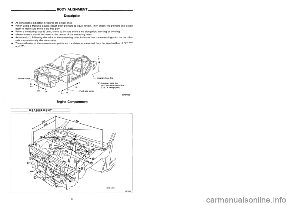
• Alldimensions indicatedinfigures areactual ones.
• When usingatracking gauge,adjustbothpointers toequal length. Thencheck thepointers andgauge
itself tomake surethere isno free play.
• When ameasuring tapeisused, check tobe sure there isno elongation, twistingorbending.
• Measurements shouldbetaken atthe center ofthe mounting holes.
• Anasterisk
(*)
following thevalue atthe measuring pointindicates thatthemeasuring pointonthe other
side issymmetrically thesame value.
• The coordinates ofthe measurement pointsarethe distances measured fromthestandard lineof"X", "V"
and "Z".
EngineCompartment
D=2T+3(mm)
D=2T+O.12 (in)
•
The electrode tipdiameter mustbereformed
properly according tothe panels thickness.
•
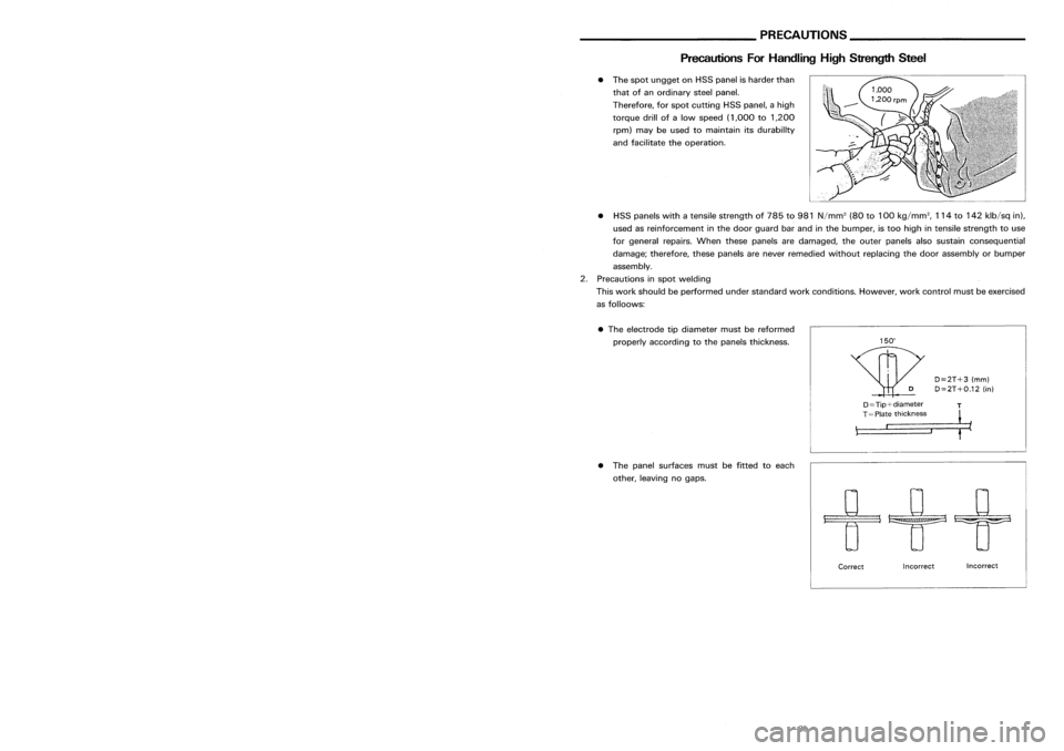
The spot ungget onHSS panel isharder than
that ofan ordinary steelpanel.
Therefore, forspot cutting HSSpanel, ahigh
torque drillofalow speed (1,000 to1,200
rpm) maybeused tomaintain itsdurability
and facilitate theoperation.
• HSS panels withatensile strength of785 to981 N/mm
2
(80to100 kg/mm
2,
114to142 klb/sq in),
used asreinforcement inthe door guard barand inthe bumper, istoo high intensile strength touse
for general repairs.Whenthesepanels aredamaged, theouter panels alsosustain consequential
damage; therefore, thesepanels arenever remedied withoutreplacing thedoor assembly orbumper
assembly.
2. Precautions inspot welding
This work should beperformed understandard workconditions. However,workcontrol mustbeexercised
as folloows:
SBF8?4GB
"Z":
Imaginary baseline
[200 mmbelow datum line
("OZ" atdesign plan)]
Front axlecenter
/
y (_)
(0)
Incorrect
Incorrect
Correct
D==Tip+diameter
T
,::=T====p=la::t_e=-=-_t_h=i_C=k=_n=_e_s=s= __,-- ~
• The panel surfaces mustbefitted toeach
other, leaving nogaps.
____
MEASURMENT _
SBT08?
-15- -30-
Page 205 of 1701
__________ BODYALIGNMENT _
_ PRECAUTIONS _
Description PrecautionsForHandling HighStrength Steel
• Alldimensions indicatedinfigures areactual ones.
• When usingatracking gauge,adjustbothpointers toequal length. Thencheck thepointers andgauge
itself tomake surethere isno free play.
• When ameasuring tapeisused, check tobe sure there isno elongation, twistingorbending.
• Measurements shouldbetaken atthe center ofthe mounting holes.
• Anasterisk
(*)
following thevalue atthe measuring pointindicates thatthemeasuring pointonthe other
side issymmetrically thesame value.
• The coordinates ofthe measurement pointsarethe distances measured fromthestandard lineof"X", "V"
and "Z".
EngineCompartment
D=2T+3(mm)
D=2T+O.12 (in)
•
The electrode tipdiameter mustbereformed
properly according tothe panels thickness.
•
The spot ungget onHSS panel isharder than
that ofan ordinary steelpanel.
Therefore, forspot cutting HSSpanel, ahigh
torque drillofalow speed (1,000 to1,200
rpm) maybeused tomaintain itsdurability
and facilitate theoperation.
• HSS panels withatensile strength of785 to981 N/mm
2
(80to100 kg/mm
2,
114to142 klb/sq in),
used asreinforcement inthe door guard barand inthe bumper, istoo high intensile strength touse
for general repairs.Whenthesepanels aredamaged, theouter panels alsosustain consequential
damage; therefore, thesepanels arenever remedied withoutreplacing thedoor assembly orbumper
assembly.
2. Precautions inspot welding
This work should beperformed understandard workconditions. However,workcontrol mustbeexercised
as folloows:
SBF8?4GB
"Z":
Imaginary baseline
[200 mmbelow datum line
("OZ" atdesign plan)]
Front axlecenter
/
y (_)
(0)
Incorrect
Incorrect
Correct
D==Tip+diameter
T
,::=T====p=la::t_e=-=-_t_h=i_C=k=_n=_e_s=s= __,-- ~
• The panel surfaces mustbefitted toeach
other, leaving nogaps.
____
MEASURMENT _
SBT08?
-15- -30-
Page 222 of 1701

PRECAUTIONS
Service Notice
• When removing orinstalling variousparts,placeacloth orpadding ontothevehicle bodytoprevent
scratches.
• Handle trim,molding, instruments, grille,etc.carefully duringremoving orinstalling. Becareful not
to soil ordamage them.
• Apply sealing compound wherenecessary wheninstalling parts.
• When applying sealingcompound, becareful thatthesealing compound doesnotprotrude from
parts.
• When replacing anymetal parts(forexample bodyouter panel, members, etc.),besure totake rust
prevention measures.
SupplementalRestraintSystem(SRS)"AIR
BAG" (DualAirBag System)
The Supplemental RestraintSystem"AirBag", usedalong withaseat belt,helps toreduce therisk or
severity ofinjury tothe driver andfront passenger inafrontal collision. TheSupplemental Restraint
System consists ofair bag modules (locatedinthe center ofthe steering wheelandonthe instrument
panel onthe passenger side),adiagnosis sensorunit,warning lamp,wiring harness andspiral cable.
Information necessarytoservice thesystem safelyisincluded inthe
RSsection
ofthis Service Manual.
WARNING:
• Toavoid rendering theSRS inoperative, whichcouldincrease therisk ofpersonal injuryordeath
in the event ofacollision whichwould resultinair bag inflation, allmaintenance mustbeperformed
by an authorized NISSANdealer.
• Improper maintenance, includingincorrectremovalandinstallation ofthe SRS, canlead topersonal
injury caused byunintentional activationofthe system.
• Donot use electrical testequipment onany circuit related tothe SRS unless instructed tointhis
Service Manual. SRSwiring harnesses arecovered withyellow insulation eitherjustbefore the
harness connectors orfor the complete harness,foreasy identification.
Supplemental RestraintSystem(SRS)"AIR
BAG" (Single AirBag System)
The Supplemental RestraintSystem"AirBag", usedalong withaseat belt,helps toreduce therisk or
severity ofinjury tothe driver inafrontal collision. TheSupplemental RestraintSystemconsists ofan
air bag module (located inthe center ofthe steering wheel),adiagnosis sensorunit,warning lamp,
wiring harness andspiral cable. Information necessarytoservice thesystem safelyisincluded inthe
RS section
ofthis Service Manual.
WARNING:
• Toavoid rendering theSRS inoperative, whichcouldincrease therisk ofpersonal injuryordeath
in the event ofacollision whichwould resultinair bag inflation, allmaintenance mustbeperformed
by an authorized NISSANdealer.
• Improper maintenance, includingincorrectremovalandinstallation ofthe SRS, canlead topersonal
injury caused byunintentional activationofthe system.
• Donot use electrical testequipment onany circuit related tothe SRS unless instructed tointhis
Service Manual.
BT-2
Page 273 of 1701

PRECAUTIONSANDPREPARATION
Precautions
SUPPLEMENTAL RESTRAINTSYSTEM(SRS)"AIRBAG"
(DUAL AIRBAG SYSTEM)
The Supplemental RestraintSystem"AirBag" usedalong with
a seat belt,helps toreduce therisk orseverity ofinjury tothe
driver andfront passenger inafrontal collision. TheSupple-
mental Restraint Systemconsists ofair bag modules (located
in the center ofthe steering wheelandonthe instrument panel
on the passenger side),adiagnosis sensorunit,warning lamp,
wiring harness andspiral cable. Information necessarytoser-
vice thesystem safelyisincluded inthe
RSsection
ofthis Ser-
vice Manual.
WARNING:
• Toavoid rendering theSRS inoperatiYe, whichcouldincrease therisk ofpersonal injuryordeath
in the event ofacollision whichwould resultinair bag inflation, allmaintenance mustbeperformed
by an authorized NISSANdealer.
• Improper maintenance, includingincorrectremovalandinstallation ofthe SRS, canlead topersonal
injury caused byunintentional activationofthe system.
• Donot use electrical testequipment onany circuit related tothe SRS unless instructed tointhis
Service Manual. SRSwiring harnesses arecovered withyellow insulation eitherjustbefore the
harness connectors orfor the complete harness,foreasy identification.
SUPPLEMENTAL RESTRAINTSYSTEM(SRS)"AIRBAG"
(SINGLE AIRBAG SYSTEM)
The Supplemental RestraintSystem"AirBag" andused along withaseat belt,helps toreduce therisk
or severity ofinjury tothe driver inafrontal collision. TheSupplemental RestraintSystemconsists of
an air bag module (located inthe center ofthe steering wheel),adiagnosis sensorunit,warning lamp,
wiring harness andspiral cable. Information necessarytoservice thesystem safelyisincluded inthe
RS section
ofthis Service Manual.
WARNING:
• Toavoid rendering theSRS inoperative, whichcouldincrease therisk ofpersonal injuryordeath
in the event ofacollision whichwould resultinair bag inflation, allmaintenance mustbeperformed
by an authorized NISSANdealer.
• Improper maintenance, includingincorrectremovalandinstallation ofthe SRS, canlead topersonal
injury caused byunintentional activationofthe system.
• Donot use electrical testequipment onany circuit related tothe SRS unless instructed tointhis
Service Manual.
BR-3
•
Page 376 of 1701
PRECAUTIONS
Supplemental RestraintSystem(SRS)"AIR
BAG" (DualAirBag System)
The Supplemental RestraintSystem"AirBag", usedalong withaseat belt,helps toreduce therisk or
severity ofinjury tothe driver andfront passenger inafrontal collision. TheSupplemental Restraint
System consists ofair bag modules (locatedinthe center ofthe steering wheelandonthe instrument
panel onthe passenger side),adiagnosis sensorunit,warning lamp,wiring harness andspiral cable.
Information necessarytoservice thesystem safelyisincluded inthe
RSsection
ofthis Service Manual.
WARNING:
• Toavoid rendering theSRS inoperative, whichcouldincrease therisk ofpersonal injuryordeath
in the event ofacollision whichwould resultinair bag inflation, allmaintenance mustbeperformed
by an authorized NISSANdealer.
• Improper maintenance, includingincorrectremovalandinstallation ofthe SRS, canlead topersonal
injury caused byunintentional activationofthe system.
• Donot use electrical testequipment onany circuit related tothe SRS unless instructed tointhis
Service Manual. SRSwiring harnesses arecovered withyellow insulation eitherjustbefore the
harness connectors orfor the complete harness,foreasy identification.
Supplemental RestraintSystem(SRS)"AIR
BAG" (Single AirBag System)
The Supplemental RestraintSystem"AirBag", usedalong withaseat belt,helps toreduce therisk or
severity ofinjury tothe driver inafrontal collision. TheSupplemental RestraintSystemconsists ofan
air bag module (located inthe center ofthe steering wheel),adiagnosis sensorunit,warning lampand
spiral cable. Information necessarytoservice thesystem safelyisincluded inthe
RSsection
ofthis
Service Manual.
WARNING: • Toavoid rendering theSRS inoperative, whichcouldincrease therisk ofpersonal injuryordeath
in the event ofacollision whichwould resultinair bag inflation, allmaintenance mustbeperformed
by an authorized NISSANdealer.
• Improper maintenance, includingincorrectremovalandinstallation ofthe SRS, canlead topersonal
injury caused byunintentional activationofthe system.
• Donot use electrical testequipment onany circuit related tothe SRS.
EL-4
Page 420 of 1701
•
SEL019Z
Vernier caliper
SEL021Z
Round 0.5-0.8 ,;,;;
~""I
Correct
~File
~ Commutator
SEL022Z STARTING
SYSTEM
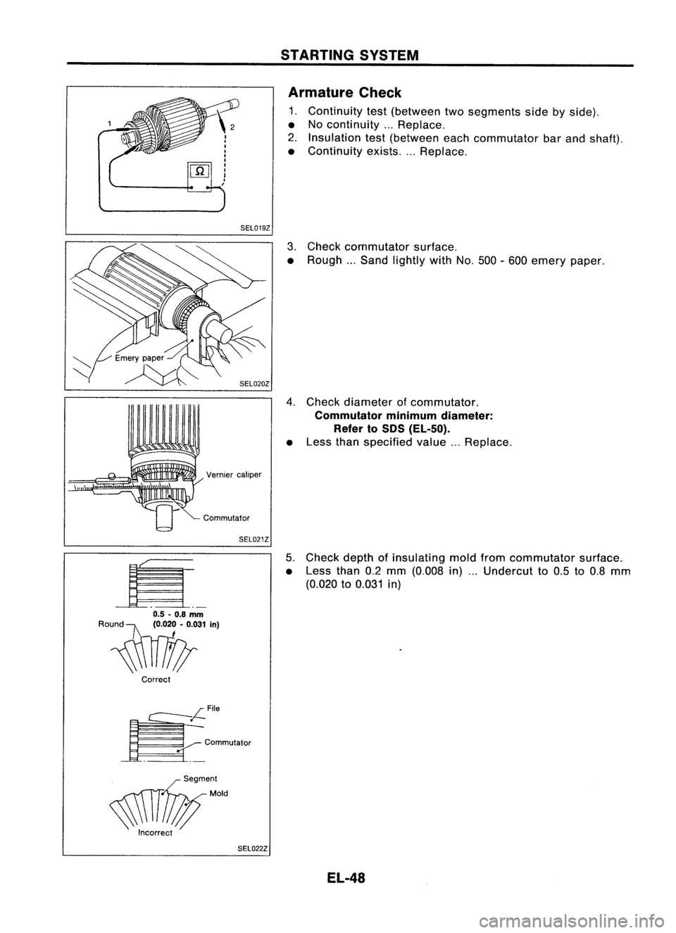
Armature Check
1. Continuity test(b
• Nocontinuit etweentwosegm .
2. Insulation tY ... Replace. entssIde byside)
• C .. est (between .
ontlnulty exists Reachcommutato b
....
eplace. rar and shaft).
3. Check comm t
• Rough Sua~or surface.
... and lightly withN
0.500 -600 emery paper.
4. Check diameter of
Commutator ml"
"commutator.
R f
mmumdia
e er toSOS (EL meter:
Less thanspe'f'
-50).
CI
led value R
... eplace.
5. Check depthof.
• Less than02 Insulating moldfrom
(0.020 to003' 1~m) (0.008 in)...Und commutator surface
. In ercutto0.5 to0.8 m'm
EL-48
Page 426 of 1701

CHARGINGSYSTEM
Trouble Diagnoses
Before conducting analternator test,make surethatthebattery isfully charged. A3D-volt voltmeter and
suitable testprobes arenecessary forthe test. Thealternator canbechecked easilybyreferring tothe
Inspection Table.
Before starting, inspectthefusible link.
WITH IeREGULATOR
Burned-out
bulb.
Replace and
proceed to
"@".
Light "ON"
Light "OFF"
Connect
connector (S,
L) and
ground F
terminal
Engine
speed: 1,500 rpm
(Measure B
terminal
voltage)
Make sure
connector (S,L)is
connected
correctly.
(HITACHI
make)
'See
4)for grounding Fterminal.
(MITSUBISHI
make)
Check or
replace drive
belt.
Light "ON"
Light "OFF"
Disconnect
connector (S,
L) and
ground L
lead wire.
Engine
speed:
1,500 rpm
Lighting
switch "ON"
With
alternator sideLterminal
grounded. internalshortoccurs
when
+
diode isshort-circuited.
Light "ON
Dim
light
Light flickers
Bright light
Light
"ON"
Light
"OFF"
Ignition
switch "ON"
@
1) Use fully charged battery.
2) light: Charge warning light
ACG :Alternator partsexcept I'Cregulator
IC-RG :IC regulator
OK :IC-alternator isingood condition.
3) When reaching "Damaged ACG",remove
alternator fromvehicle anddisassembly, inspect
and correct orreplace faultyparts.
4) *Method ofgrounding Fterminal (HITACHI make
only)
Gasoline enginemodel
Contact tipofwire withbrush andattach
wire toalternator body.
~~~
;;z..'~~.~
~~~/j
S$.~~'
s<(r~, -
Brush liftwire
;;.. ~ Q<:::z"d,l'T7.
~ .. ~ ~-)o,IJ!"-f/
- -~~ C);
0~~/
'~-/i ~-,~
-~j~n
- <::::; -~ \•
'" 1A/-'
SEL030Z
5) Terminals
"S","l","B"
and
"E"
aremarked onrear cover ofalternator.
EL-54
Page 447 of 1701
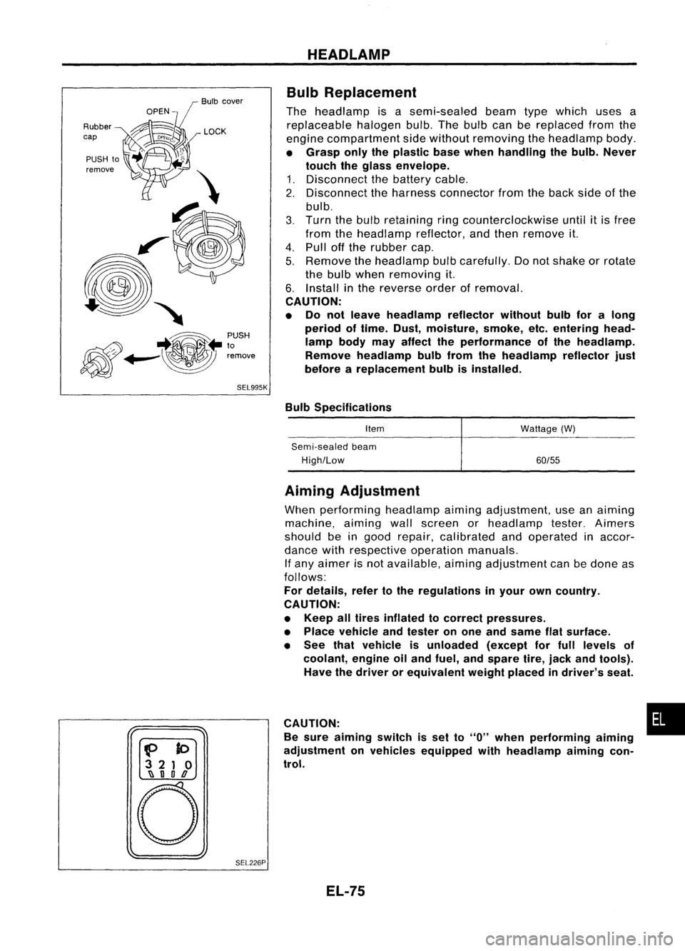
Bulbcover
SEL995K HEADLAMP
Bulb Replacement
The headlamp isasemi-sealed beamtypewhich usesa
replaceable halogenbulb.Thebulb canbereplaced fromthe
engine compartment sidewithout removing theheadlamp body.
• Grasp onlytheplastic basewhen handling thebulb. Never
touch theglass envelope.
1. Disconnect thebattery cable.
2. Disconnect theharness connector fromtheback sideofthe
bulb.
3. Turn thebulb retaining ringcounterclockwise until
it
is free
from theheadlamp reflector,andthen remove it.
4. Pull offthe rubber cap.
5. Remove theheadlamp bulbcarefully. Donot shake orrotate
the bulb when removing it.
6. Install inthe reverse orderofremoval.
CAUTION:
• Do not leave headlamp reflector withoutbulbforalong
period oftime. Dust,moisture, smoke,etc.entering head-
lamp bodymayaffect theperformance ofthe head lamp.
Remove headlamp bulbfrom thehead lamp reflector just
before areplacement bulbisinstalled.
Bulb Specifications
Item
Semi-sealed beam
High/Low Wattage
(W)
60/55
f>
to
3 21 0
~ nOD
o
SEL226PAiming
Adjustment
When performing headlamp aiming adjustment, useanaiming
machine, aimingwallscreen orheadlamp tester.Aimers
should beingood repair, calibrated andoperated inaccor-
dance withrespective operationmanuals.
If any aimer isnot available, aimingadjustment canbedone as
follows:
For details, refertothe regulations inyour owncountry.
CAUTION:
• Keep alltires inflated tocorrect pressures.
• Place vehicle andtester onone and same flatsurface.
• See thatvehicle isunloaded (exceptforfull levels of
coolant, engineoiland fuel, andspare tire,jack andtools).
Have thedriver orequivalent weightplaced indriver's seat.
CAUTION: •
Be sure aiming switchisset to
"0"
when performing aiming
adjustment onvehicles equipped withheadlamp aiming con-
trol.
EL-75