Page 1236 of 1701
IdentificationNo.
\ca
p
\
NO.1
t.:?
Enginefront
SEM420C CYLINDER
BLOCK
Assembly (Cont'd)
•
Front
Pistonringcompressor
SEM293C
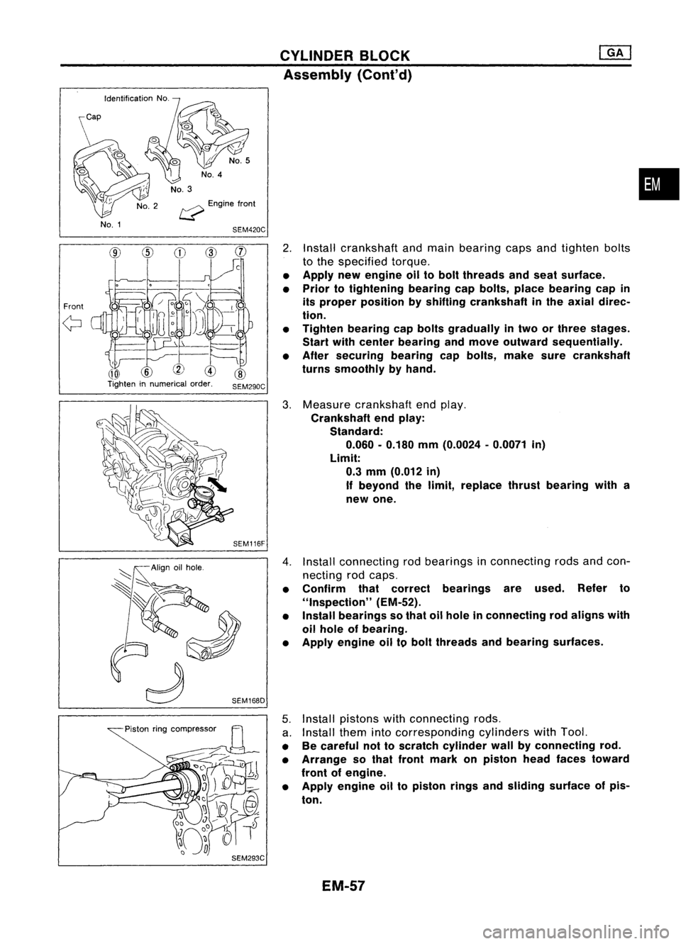
2.
Install crankshaft andmain bearing capsandtighten bolts
to the specified torque.
• Apply newengine oiltobolt threads andseat surface.
• Prior totightening bearingcapbolts, placebearing capin
its proper position byshifting crankshaft inthe axial direc-
tion.
• Tighten bearing capbolts gradually intwo orthree stages.
Start withcenter bearing andmove outward sequentially.
• After securing bearingcapbolts, makesurecrankshaft
turns smoothly byhand.
3. Measure crankshaft endplay.
Crankshaft endplay:
Standard:
0.060 -0.180 mm(0.0024 -0.0071 in)
Limit: 0.3 mm (0.012 in)
If beyond thelimit, replace thrustbearing witha
new one.
4. Install connecting rodbearings inconnecting rodsandcon-
necting rodcaps.
• Confirm thatcorrect bearings areused. Referto
"Inspection" (EM-52).
• Install bearings sothat oilhole inconnecting rodaligns with
oil hole ofbearing.
• Apply engine oiltobolt threads andbearing surfaces.
5. Install pistons withconnecting rods.
a. Install themintocorresponding cylinderswithTool.
• Becareful nottoscratch cylinder wallbyconnecting rod.
• Arrange sothat front mark onpiston headfaces toward
front ofengine.
• Apply engine oiltopiston ringsandsliding surface ofpis-
ton.
EM-57
Page 1270 of 1701
SEM083DCYLINDER
HEAD
Inspection (Cont'd)
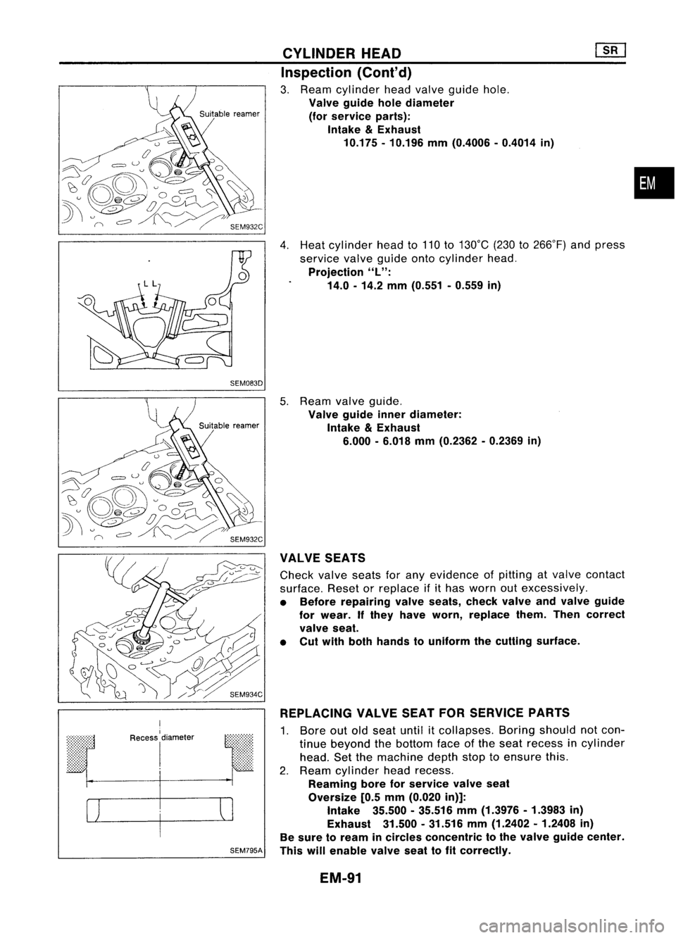
3. Ream cylinder headvalve guide hole.
Valve guide holediameter
(for service parts):
Intake
&
Exhaust
10.175 -10.196 mm(0.4006 -0.4014 in)
4. Heat cylinder headto110 to130°C (230to266°F) andpress
service valveguide ontocylinder head.
Projection
"L":
14.0 -14.2 mm(0.551 -0.559 in)
•
r
I
Recess
I
diameter
I
SEM795A
5.
Ream valveguide.
Valve guide innerdiameter:
Intake
&
Exhaust
6.000 -6.018 mm(0.2362 -0.2369 in)
VALVE SEATS
Check valveseatsforany evidence ofpitting atvalve contact
surface. Resetorreplace ifithas worn outexcessively.
• Before repairing valveseats, checkvalveandvalve guide
for wear. Ifthey have worn, replace them.Thencorrect
valve seat.
• Cut with both hands touniform thecutting surface.
REPLACING VALVESEATFORSERVICE PARTS
1. Bore outoldseat until
it
collapses. Boringshould notcon-
tinue beyond thebottom faceofthe seat recess incylinder
head. Setthemachine depthstoptoensure this.
2. Ream cylinder headrecess.
Reaming boreforservice valveseat
Oversize [0.5mm (0.020 in)]:
Intake 35.500-35.516 mm(1.3976 -1.3983 in)
Exhaust 31.500.31.516 mm(1.2402 -1.2408 in)
Be sure toream incircles concentric tothe valve guide center.
This willenable valveseattofit correctly.
EM-91
Page 1275 of 1701
/1!!i1*Shim
~ Rocker armguide
Ij9 ~~
Valve collet
~ I:::
Valvespring
l!I
retainer
I!1!i! ~
'Valve spring
~ ~~ ~Valve springseat
j
Valveoilseal ~
Valve
SEM364DCYLINDER
HEAD ~
Assembly (Cont'd)
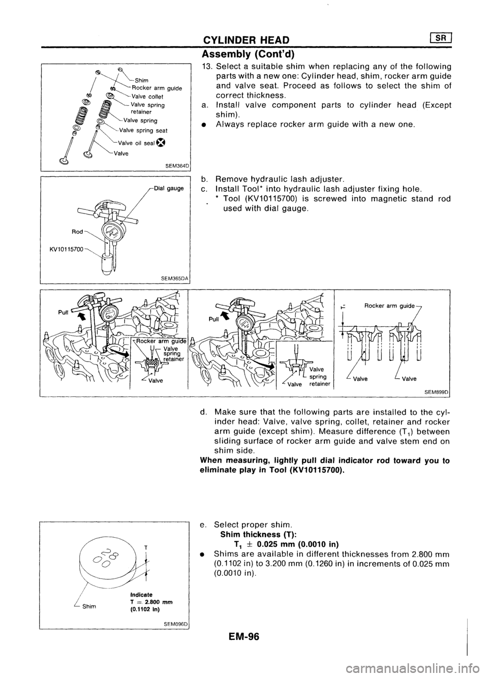
13. Select asuitable shimwhen replacing anyofthe following
parts withanew one: Cylinder head,shim, rocker armguide
and valve seat.Proceed asfollows toselect theshim of
correct thickness.
a. Install valvecomponent partstocylinder head(Except
shim).
• Always replace rockerarmguide withanew one.
Rod
KV10115700 Dial
gauge
SEM365DA
b.
Remove hydraulic lashadjuster.
c. Install Tool*intohydraulic lashadjuster fixinghole.
* Tool (KV10115700) isscrewed intomagnetic standrod
used withdialgauge.
SEM899D
\.
/~-
/
L
shim
Indicate
T
=
2.800 mm
(0.1102 In)
SEM096D
d.
Make surethatthefollowing partsareinstalled tothe cyl-
inder head: Valve, valvespring, collet,retainer androcker
arm guide (except shim).Measure difference (T
1)
between
sliding surface ofrocker armgUide andvalve stemendon
shim side.
When measuring, lightlypulldialindicator rodtoward youto
eliminate playinTool (KV10115700).
e. Select proper shim.
Shim thickness (T):
T
1
:l:0.025 mm(0.0010 in)
• Shims areavailable indifferent thicknesses from2.800 mm
(0.1102 in)to3.200 mm(0.1260 in)inincrements of0.025 mm
(0.0010 in).
EM-96
Page 1279 of 1701
SEM312DENGINE
REMOVAL
Removal (Cont'd)
12. Remove enginewithtransaxle asshown.
Installation
1. Install engine mounting bracketandfixing bolts.
Be sure thatinsulators arecorrectly positioned onthe brack-
ets.
2. Carefully lowertheengine ontoengine mounting insulators.
When installing theengine, adjusttheheight ofthe engine
mounting asshown. (ForM/T)
3. Installation isinthe reverse orderofremoval.
EM-100
Page 1285 of 1701
#5
#4 ~
~i1
hole #3~~ \)
#2 ~~,
#1~~~ ~~
12 ~~
Engine front~
SEM685D
SEM964
SEM313D CYLINDER
BLOCK
Inspection (Cont'd)
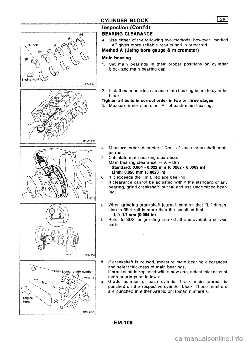
BEARING CLEARANCE
• Use either ofthe following twomethods, however, method
"A" gives morereliable resultsandispreferred.
Method A(Using boregauge
&
micrometer)
Main bearing
1. Set main bearings intheir proper positions oncylinder
block andmain bearing cap.
2. Install mainbearing capand main bearing beamtocylinder
block.
Tighten allbolts incorrect orderintwo orthree stages.
3. Measure innerdiameter "A"ofeach main bearing.
4. Measure outerdiameter "Om"ofeach crankshaft main
journal.
5. Calculate mainbearing clearance.
Main bearing clearance
=
A-Om
Standard: 0.004•0.022 mm(0.0002 •0.0009 in)
Limit: 0.050mm(0.0020 in)
6. Ifitexceeds thelimit, replace bearing.
7. Ifclearance cannotbeadjusted withinthestandard ofany
bearing, grindcrankshaft journalanduseundersized bear-
ing.
a. When grinding crankshaft journal,confirmthat"L"dimen-
sion infillet rollismore thanthespecified limit.
"L":
0.1mm (0.004 in)
b. Refer toSOS forgrinding crankshaft andavailable service
parts.
8. Ifcrankshaft isreused, measure mainbearing clearances
and select thickness ofmain bearings.
If crankshaft isreplaced withanew one, select thickness of
main bearings asfollows:
a. Grade number ofeach cylinder blockmainjournal is
punched onthe respective cylinderblock.These numbers
are punched ineither Arabic orRoman numerals.
EM-106
Page 1287 of 1701
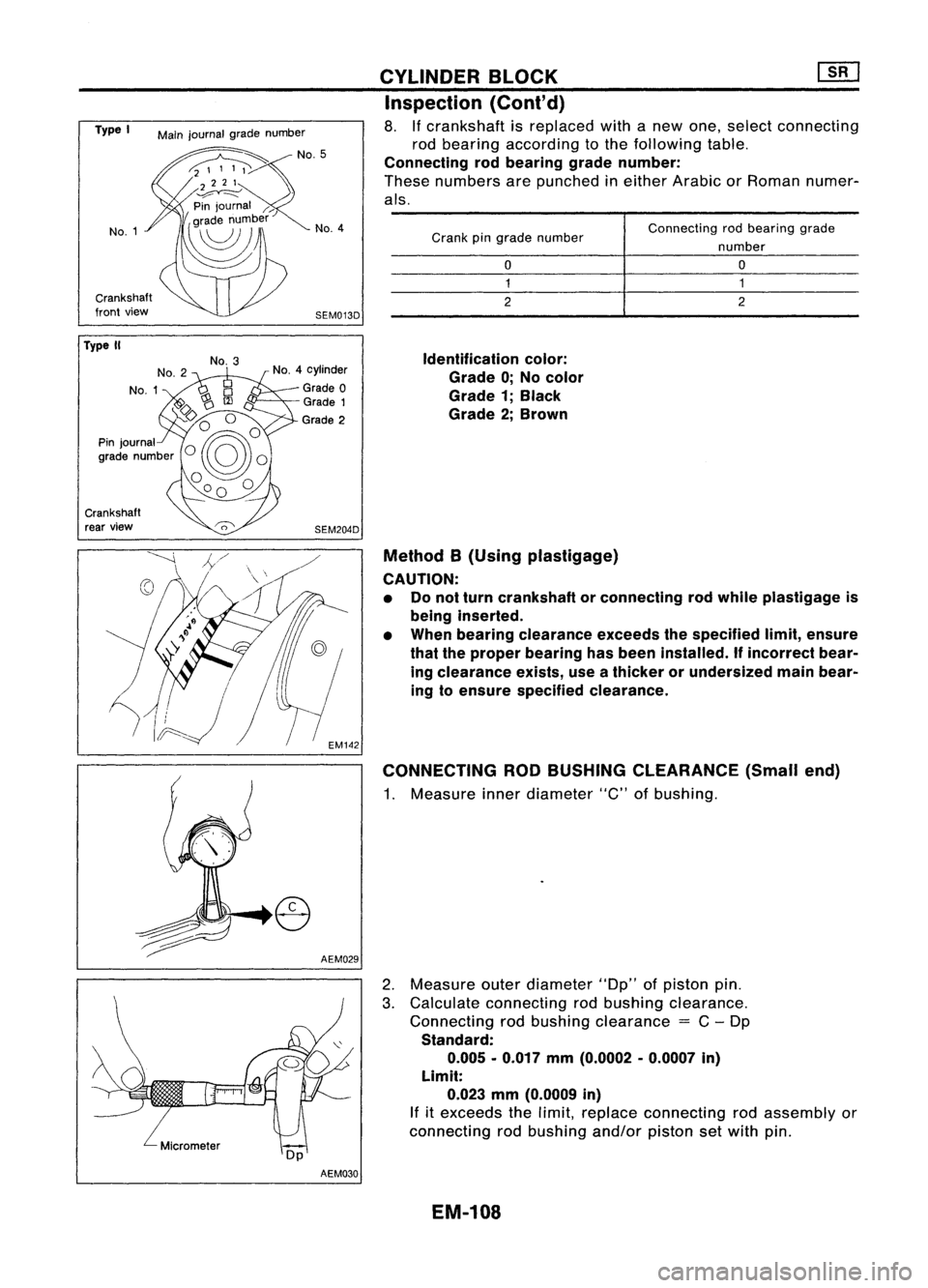
Connectingrodbearing grade
number
o
1
2
o
1
2
Crank
pingrade number
Identification color:
Grade 0;No color
Grade 1;Black
Grade 2;Brown
Method B(Using plastigage)
CAUTION: • Donot turn crankshaft orconnecting rodwhile plastigage is
being inserted.
• When bearing clearance exceedsthespecified limit,ensure
that theproper bearing hasbeen installed.
If
incorrect bear-
ing clearance exists,useathicker orundersized mainbear-
ing toensure specified clearance.
CONNECTING RODBUSHING CLEARANCE (Smallend)
1. Measure innerdiameter "C"ofbushing.
CYLINDER
BLOCK ~
Inspection (Cont'd)
8. Ifcrankshaft isreplaced withanew one, select connecting
rod bearing according tothe following table.
Connecting rodbearing gradenumber:
These numbers arepunched ineither Arabic orRoman numer-
als.
AEM029
SEM013D
No.
4
SEM204D
No.
4cylinder
Grade 0
Grade 1
Grade 2
No.
3
Main
journal gradenumber
No.1
Crankshaft
front view
Type
I
Crankshaft rear view
Type
II
2.Measure outerdiameter "Dp"ofpiston pin.
3. Calculate connecting rodbushing clearance.
Connecting rodbushing clearance
=
C-Dp
Standard: 0.005 -0.017 mm(0.0002 -0.0007 in)
Limit: 0.023 mm(0.0009 in)
If
itexceeds thelimit, replace connecting rodassembly or
connecting rodbushing and/orpistonsetwith pin.
AEM030
EM-108
Page 1289 of 1701
Frontmark
Oil hole
Engine
front Piston
grade
number
Cylindernumber
SEM946C
Top
Oil
SEM199F CYLINDER
BLOCK []:[J
Assembly (Conl'd)
2. Heat piston to60 to70°C (140to158°F) andassemble piston,
piston pin,connecting rodand new snap ring.
• Align thedirection ofpiston andconnecting rod.
• Numbers stampedonconnecting rodand capcorrespond to
each cylinder.
• After assembly, makesureconnecting rodswings
smoothly.
3. Set piston ringsasshown.
CAUTION:
• When piston ringsarenotreplaced, makesurethatpiston
rings aremounted intheir original positions.
• When replacing pistonrings,thosewithout punchmarks can
be mounted witheither sideup.
Oil ring
expander
*v
Engine!/
front
(:J
#5
#4 ~
~il hole #3~~ \)
#2 ~~ ,
#1~~~ ~~
12 ~~
Engine front~
SEM685DCRANKSHAFT
1. Set main bearings intheir proper positions oncylinder
block andmain bearing cap.
• Confirm thatcorrect mainbearings areused. Referto
"Inspection" ofthis section.
• Apply newengine oiltobearing surfaces.
EM-110
Page 1290 of 1701
![NISSAN ALMERA N15 1995 Service Manual Tighteninnumerical order.
'::::::-.... Alignoilhole.
~~
'~~-
SEM015D
SEM159B CYLINDER
BLOCK [][]
Assembly (Cont'd)
2. Install crankshaft andmain bearing capsandtighten bolts
to the spec NISSAN ALMERA N15 1995 Service Manual Tighteninnumerical order.
'::::::-.... Alignoilhole.
~~
'~~-
SEM015D
SEM159B CYLINDER
BLOCK [][]
Assembly (Cont'd)
2. Install crankshaft andmain bearing capsandtighten bolts
to the spec](/manual-img/5/57349/w960_57349-1289.png)
Tighteninnumerical order.
'::::::-.... Alignoilhole.
~~
'~~-
SEM015D
SEM159B CYLINDER
BLOCK [][]
Assembly (Cont'd)
2. Install crankshaft andmain bearing capsandtighten bolts
to the specified torque.
• Apply newengine oiltothread ofbearing capbolts.
• Prior totightening bearingcapbolts, shiftcrankshaft back
and forth toproperly seatthebearing cap.
• Tightening procedure
a. Tighten allbolts to26 to32 N'm (2.7to3.3 kg-m, 20to24 •
in-Ib).
b. Turn allbolts 75to80 degrees clockwise withTool orsuit-
able angle wrench.
c. Loosen allbolts completely.
d. Tighten allbolts to32 to38 N'm (3.3to3.9 kg-m, 24to28
ft-Ib).
e. Turn allbolts 45to50 degrees clockwise withTool orsuit-
able angle wrench.
• Ifan angle wrench isnot available, markallbearing cap
bolts onthe side facing engine rear.Then, turneach bolt
specified degreesclockwise. Confirmangleofdegrees with
a graduator, notbyeye-measurement.
• After securing bearingcapbolts, makesurecrankshaft
turns smoothly byhand.
3. Measure crankshaft endplay.
Crankshaft endplay:
Standard
0.10 -0.26 mm(0.0039 -0.0102 in)
Limit
0.30 mm(0.0118 in)
If beyond thelimit, replace thrustbearings withnewones.
4. Install connecting rodbearings inconnecting rodsandcon-
necting rodcaps.
• Confirm thatcorrect bearings areused. Referto
"I nspection" .
• Install bearings sothat oilhole inconnecting rodaligns with
oil hole ofbearing.
• Apply newengine oiltobolt threads andbearing surfaces.
5. Install pistons withconnecting rods.
a. Install themintocorresponding cylinderswithTool.
• Becareful nottoscratch cylinder wallbyconnecting rod.
• Arrange sothat front mark onpiston headfaces toward
front ofengine.
• Apply newengine oiltopiston ringsandsliding surface of
piston.
EM-111