Page 448 of 1701
-
Up and down adjusting screw
, \ ,I/
MEL614DHEADLAMP
Aiming Adjustment (Cont'd)
LOW BEAM
1. Turn headlamp lowbeam on.
2. Use adjusting screwstoperform aimingadjustment.
• First tighten theadjusting screwallthe way andthen make
adjustment byloosening thescrew.
• Adjust headlamps sothat main axisoflight isparallel to
center lineofbody andisaligned withpoint Pshown in
illustration.
• Figure tothe leftshows headlamp aiming pattern fordriv-
ing onright sideofroad; fordriving onleft side ofroad,
aiming pattern isreversed.
• Dotted linesinillustration showcenter ofhead lamp.
"H":
Horizontal centerlineofheadlamps
"W
L":
Distance betweeneachheadlamp center
"l":
5,000mm(196.85 in)
"e":
65mm (2.56 in)
Height of
lamp centers
I
f
P \
/~
Vertical
centerline
ahead ofheadlamps -
"H":
Horizontal
center line
of headlamps
d
=
ACCEPTABLE RANGE
SEL2541
EL-76
Page 688 of 1701

ON-VEHICLESERVICE
Front Wheel Alignment
Before checking frontwheel alignment, besure tomake apre-
liminary inspection (Unladen*).
*: Fuel, radiator coolantandengine oilfull. Spare tire,jack,
hand tools andmats indesignated positions.
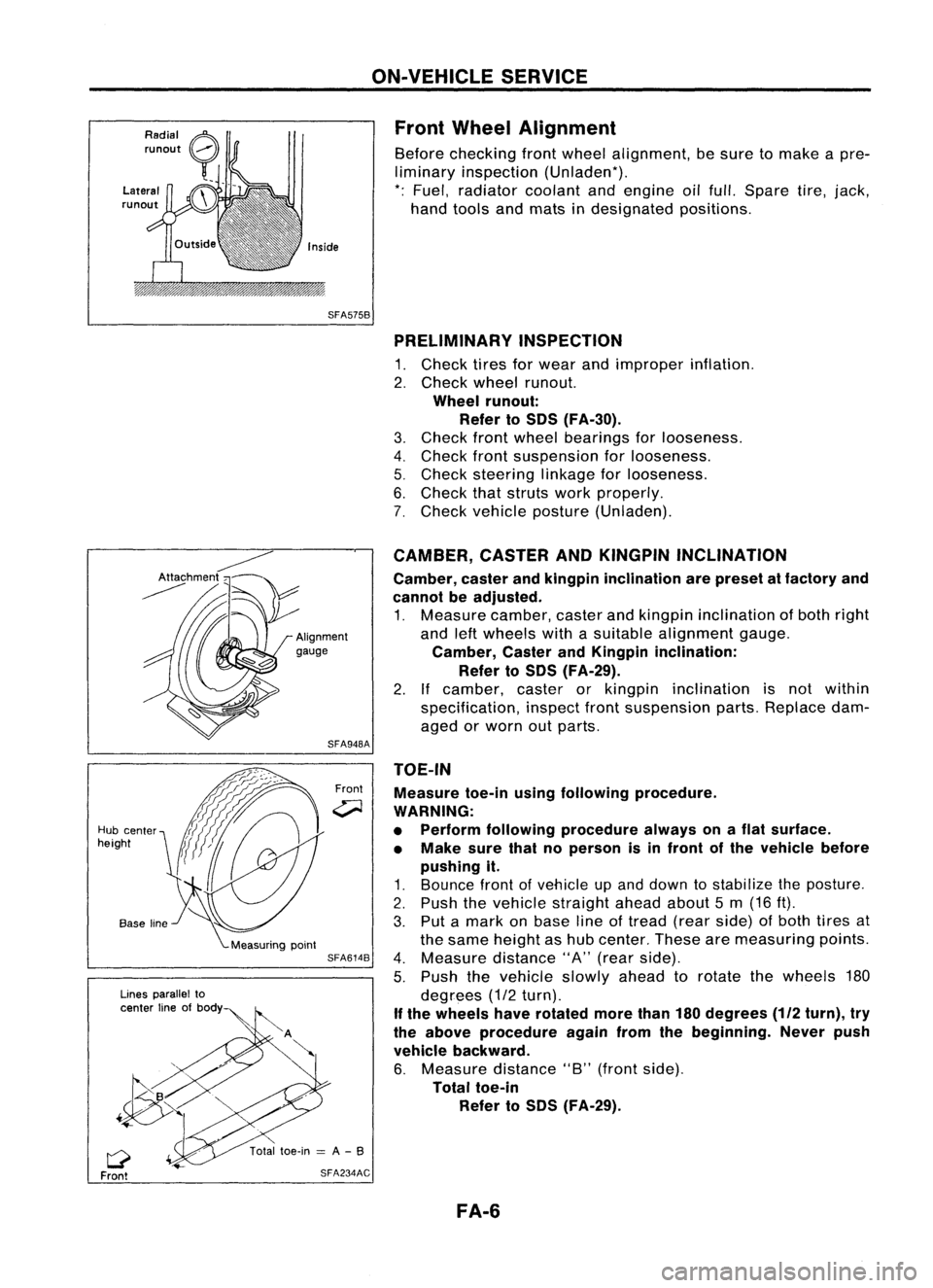
SFA575B PRELIMINARY INSPECTION
1. Check tiresforwear andimproper inflation.
2. Check wheelrunout.
Wheel runout:
Refer toSOS (FA-30).
3. Check frontwheel bearings forlooseness.
4. Check frontsuspension forlooseness.
5. Check steering linkageforlooseness.
6. Check thatstruts workproperly.
7. Check vehicle posture (Unladen).
TOE-IN Measure toe-inusingfollowing procedure.
WARNING:
• Perform following procedure alwaysonaflat surface.
• Make surethatnoperson isin front ofthe vehicle before
pushing it.
1. Bounce frontofvehicle upand down tostabilize theposture.
2. Push thevehicle straight aheadabout5m (16 ft).
3. Put amark onbase lineoftread (rearside) ofboth tires at
the same height ashub center. Thesearemeasuring points.
4. Measure distance"A"(rear side).
5. Push thevehicle slowlyaheadtorotate thewheels 180
degrees (1/2turn).
If the wheels haverotated morethan180degrees
(112
turn), try
the above procedure againfromthebeginning. Neverpush
vehicle backward.
6. Measure distance"B"(front side).
Total toe-in
Refer toSOS (FA-29).
CAMBER,
CASTERANDKINGPIN INCLINATION
Camber, casterandkingpin inclination arepreset atfactory and
cannot beadjusted.
1. Measure camber,casterandkingpin inclination ofboth right
and leftwheels withasuitable alignment gauge.
Camber, CasterandKingpin inclination:
Refer toSOS (FA-29).
2. Ifcamber, casterorkingpin inclination isnot within
specification, inspectfrontsuspension parts.Replace dam-
aged orworn outparts.
Front
SFA948A
SFA614B
SFA234AC
Lines
parallel to
center lineofbody
Q
Front
Hub
center
height
FA-6
Page 912 of 1701
TROUBLEDIAGNOSIS FORNON-DETECTABLE ITEMS
Heated Oxygen Sensor(H02S)(Cont'd)
@
Loosen andretighten engineground
screws.
OK
CHECK COMPONENT
(Heated oxygensensorheater).
Refer to"COMPONENT INSPECTION"
below.
OK
Disconnect andreconnect harnesscon-
ne~tors inthe circuit. Thenretest.
Trouble isnot fixed.
Check ECMpinterminals fordamage
or the connection ofECM harness con-
nector. Reconnect ECMharness con-
nector andretest.
Troubleisnot fixed.
Replace heatedoxygen sensor.
COMPONENT INSPECTION NG
Replace heatedoxygen
sensor.
•
DISCONNECT
I~J
00
SEF586Q
Heated
oxygen sensorheater
Check resistance betweenterminals
@
and
CD.
Resistance: 2.3-4.3Q at25°C (77°F)
Check continuity betweenterminals @and
CD,
@
and @.
Continuity shouldnotexist.
If NG, replace theheated oxygen sensor.
CAUTION:
• Discard anyoxygen sensorwhichhasbeen dropped from
a height ofmore than0.5m(19.7 in)onto ahard surface
such asaconcrete floor;useanew one.
EC-193
Page 916 of 1701
•
Repair
harness orcon-
nectors.
NG
OK
Loosen andretighten engineground
screws. CHECK
INPUTSIGNAL CIRCUIT.
1. Stop engine.
2. Disconnect ECMharness connector
and oxygen sensorharness connec-
tor.
3. Check harness continuity between
ECM terminal
@
or
@
and terminal
CD.
Continuity shouldexist.
If OK, check harness forshort.
~iV
@
TROUBLE
DIAGNOSIS FORNON-DETECTABLE ITEMS
Oxygen Sensor(02S)(Conl'd)
@
~Io
ECM
19'
CONNECTOR
II
46 19
II
OK
Disconnect andreconnect harnesscon-
nectors inthe circuit. Thenretest.
@:
ForAustralia M/Tmodels
@:
Except forEurope andIsrael
SEF182R
Trouble
isnot fixed.
Check ECMpinterminals fordamage
or the connection ofECM harness con-
nector. Reconnect ECMharness con-
nector andretest.
Troubleisnot fixed.
Replace oxygensensor.
CAUTION:
• Discard anyoxygen sensorwhichhasbeen dropped from
a height ofmore than0.5m(19.7 in)onto ahard surface
such asaconcrete floor;useanew one.
EC-197
Page 1177 of 1701
SLC904
CD
@
10~~103~ \
~' ENGINE
COOLING SYSTEM
I
GA, SR,CD
I
Radiator (Aluminum type)(Cont'd)
4. Caulk tankinspecified sequence withTool.
•
Keep toolperpendicular to
the radiator.
o
X
(Grip isinsufficient.)
SLC896
• Use pliers inthe locations whereToolcannot beused.
5. Make surethattherim iscompletely crimpeddown.
Standard height
"H":
8.0 -8.4 mm (0.315 -0.331 in)
6. Confirm thatthere isno leakage.
Refer toInspection.
INSPECTION
Apply pressure withTool.
Specified pressurevalue:
157 kPa (1.57 bar,1.6kg/cm
2,
23psi)
WARNING:
To prevent therisk ofthe hose coming undonewhileunder
pressure, securelyfastenitdown withahose clamp.
Attach ahose tothe oilcooler aswell.
(A
IT models only)
SLC933 LC-39
Page 1213 of 1701

CYLINDERHEAD
CAUTION:
• When installing camshaft, oilseals orother sliding parts,
lubricate contacting surfaceswithnewengine oil.
• When tightening cylinderheadbolts, camshaft sprocket
bolts andcamshaft bracketbolts,lubricate threadportions
and seat surfaces ofbolts withnewengine oil.
• Attach tagstovalve lifters soas not tomix them up.
Removal
• This removal isthe same procedure asthose fortiming
chain. Referto"Removal" in"TIMING CHAIN"(EM-20).
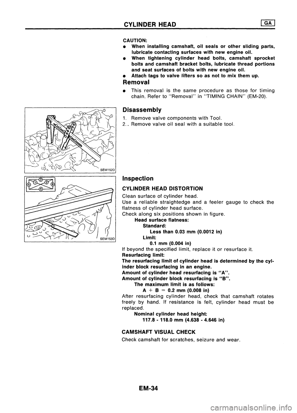
Disassembly
1. Remove valvecomponents withTool.
2 .. Remove valveoilseal withasuitable tool.
Inspection
CYLINDER HEADDISTORTION
Clean surface ofcylinder head.
Use areliable straightedge andafeeler gauge tocheck the
flatness ofcylinder headsurface.
Check alongsixpositions showninfigure.
Head surface flatness:
Standard:
Less than0.03mm(0.0012 in)
Limit: 0.1 mm (0.004 in)
If beyond thespecified limit,replace itor resurface it.
Resurfacing limit:
The resurfacing limitofcylinder headisdetermined bythe cyl-
inder block resurfacing inan engine.
Amount ofcylinder headresurfacing is
"A".
Amount ofcylinder blockresurfacing is
"8".
The maximum limitisas follows:
A +8
=
0.2 mm (0.008 in)
After resurfacing cylinderhead,check thatcamshaft rotates
freely byhand. Ifresistance isfelt, cylinder headmust be
replaced.
Nominal cylinderheadheight:
117.8 -118.0 mm(4.638 .4.646 in)
CAMSHAFT VISUALCHECK
Check camshaft forscratches, seizureandwear.
EM-34
Page 1214 of 1701

SEM154D
SEM549A CYLINDER
HEAD
Inspection (Cont'd)
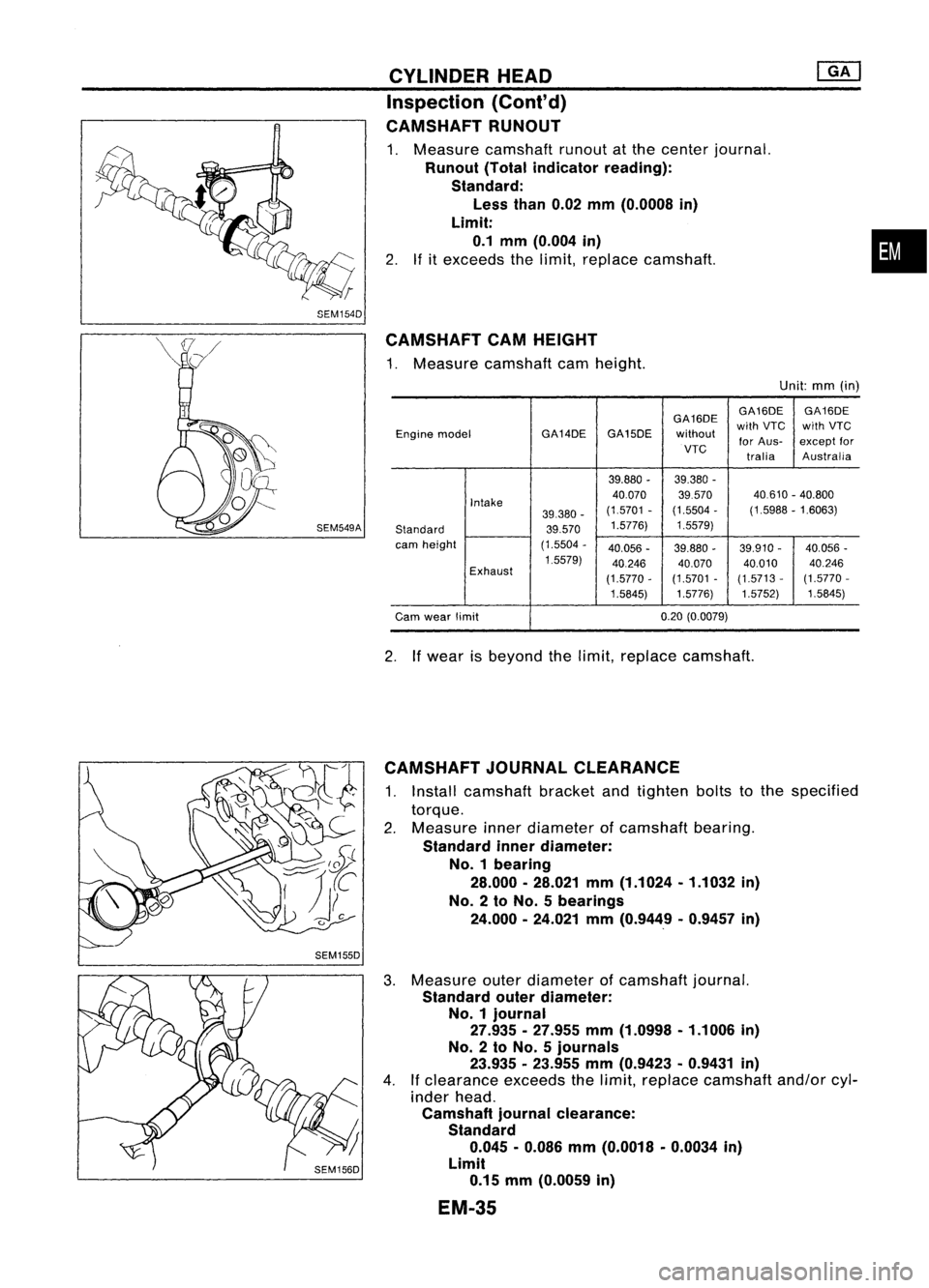
CAMSHAFT RUNOUT
1. Measure camshaft runoutatthe center journal.
Runout (Totalindicator reading):
Standard: Less than0.02mm(0.0008 in)
Limit: 0.1 mm (0.004 in)
2. Ifitexceeds thelimit, replace camshaft.
CAMSHAFT CAMHEIGHT
1. Measure camshaft camheight.
Unit:mm(in)
GA16DE GA16DE
GA16DE
Engine model GA14DEGA15DE
withoutwith
VTC withVTC
for Aus- except
for
VTC traliaAustralia
39.880 -39.380 -
Intake 40.070
39570 40.610
-40.800
39.380 -(1.5701
-(1.5504 -(1.5988 -1.6063)
Standard 39.5701.5776)
1.5579)
cam height (1.5504-
40.056 -39.880 -39.910 -40.056
-
1.5579) 40.24640.07040.01040.246
Exhaust (1.5770-(1.5701
-(1.5713 -(1.5770
-
1.5845) 1.5776}1.5752)
1.5845}
Cam wear limit 0.20
(O.0079)
2. Ifwear isbeyond thelimit, replace camshaft.
•
CAMSHAFT JOURNALCLEARANCE
1. Install camshaft bracketandtighten boltstothe specified
torque.
2. Measure innerdiameter ofcamshaft bearing.
Standard innerdiameter:
No. 1bearing
28.000.28.021 mm(1.1024.1.1032 in)
No. 2to No. 5bearings
24.000 •24.021 mm(0.9449 .0.9457 in)
3. Measure outerdiameter ofcamshaft journal.
Standard outerdiameter:
No.1 journal
27.935.27.955 mm(1.0998 .1.1006 in)
No.2 toNo.5 journals
23.935 -23.955 mm(0.9423 •0.9431 in)
4. Ifclearance exceedsthelimit, replace camshaft and/orcyl-
inder head.
Camshaft journalclearance:
Standard 0.045 •0.086 mm(0.0018 •0.0034 in)
Limit 0.15 mm(0.0059 in)
EM-3S
Page 1218 of 1701

T(Margin thickness)
--1,-
ml
a
III' ~
o
~-
-L
d
SEM8928
I
.\
SEM188A
CYLINDER
HEAD
Inspection (Conl'd)
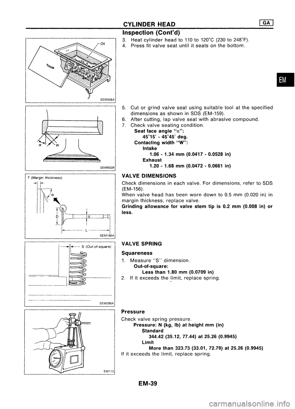
3. Heat cylinder headto110 to120°C (230to248°F).
4. Press fitvalve seatuntilitseats onthe bottom .
5. Cut orgrind valve seatusing suitable toolatthe specified
dimensions asshown inSOS (EM-159).
6. After cutting, lapvalve seatwithabrasive compound.
7. Check valveseating condition.
Seat faceangle "a":
45°15' -45°45' deg.
Contacting width"W":
Intake
1.06 -1.34 mm(0.0417 -0.0528 in)
Exhaust
1.20 -1.68 mm(0.0472 -0.0661 in)
VALVE DIMENSIONS
Check dimensions ineach valve. Fordimensions, refertoSOS
(EM-156).
When valveheadhasbeen worn down to0.5 mm (0.020 in)in
margin thickness, replacevalve.
Grinding allowance forvalve stemtipis0.2 mm (0.008 in)or
less.
•
SEM288A VALVE
SPRING
Squareness
1. Measure "S"dimension.
Out-of-square: Less than1.80mm(0.0709 in)
2. Ifitexceeds thelimit, replace spring.
EM113
Pressure
Check valvespring pressure.
Pressure: N(kg, Ib)atheight mm(in)
Standard 344.42 (35.12, 77.44)at25.26 (0.9945)
Limit More than323.73 (33.01, 72.79)at25.26 (0.9945)
If itexceeds thelimit, replace spring.
EM-39