Page 1350 of 1701

SERVICEDATAANDSPECIFICATIONS (SDS)
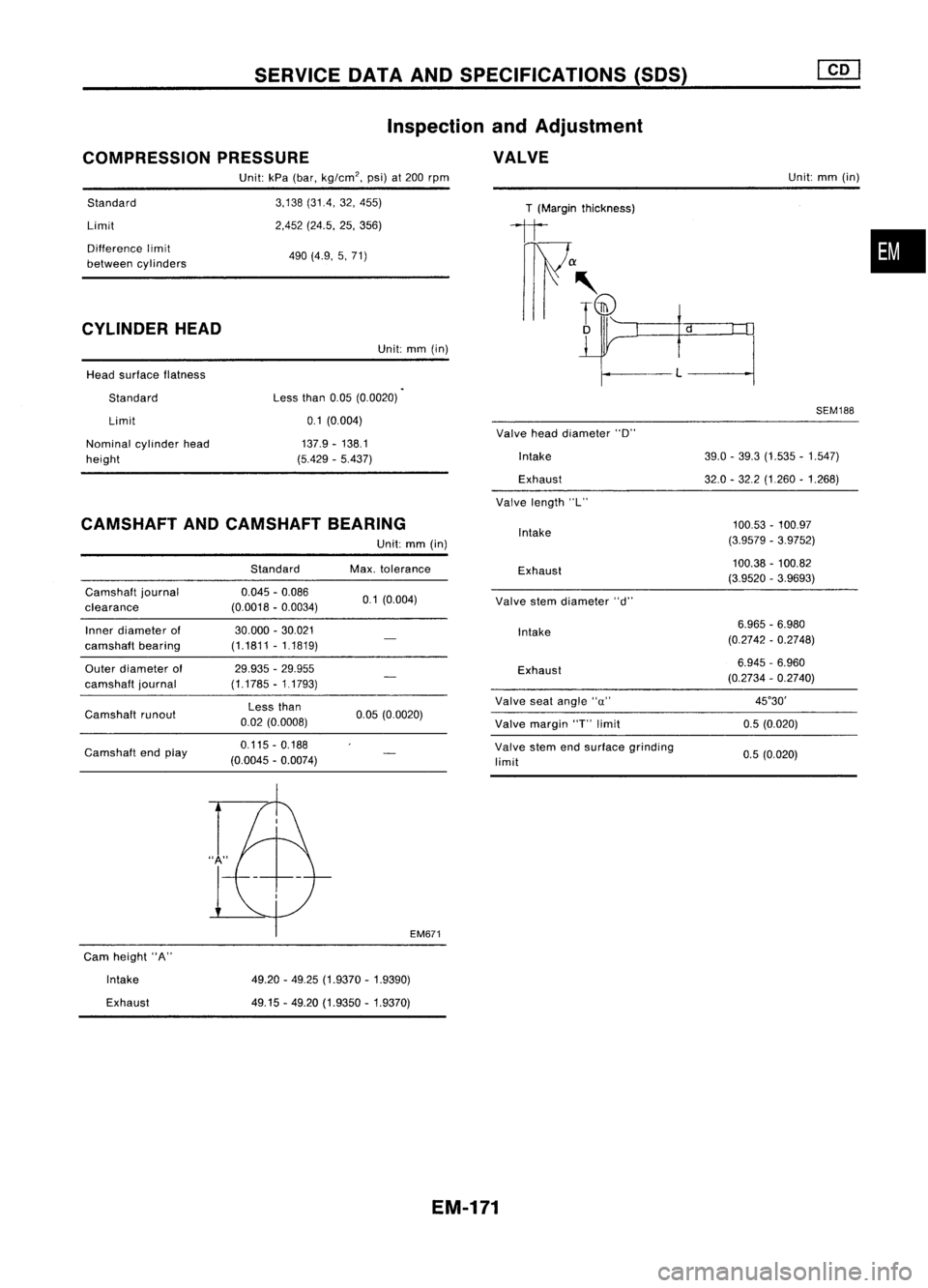
COMPRESSION PRESSURE Inspection
andAdjustment
VALVE
Standard
Limit
Difference limit
between cylinders
CYLINDER HEAD
Head surface flatness
Standard Limit
Nominal cylinderhead
height Unit:
kPa(bar, kg/cm
2,
psi)at
200
rpm
3,138 (31.4, 32,455)
2,452 (24.5, 25,356)
490 (4.9, 5,71)
Unit: mm(in)
Less than
0.05(0.0020)
0.1 (0,004)
137.9 -138.1
(5.429 -5.437)
T
(Margin thickness)
1t
f"~ if
Valve headdiameter "D"
Intake
Exhaust
Valve length "L" Unit:
mm(in)
SEM188
39.0 -39.3 (1.535 -1.547)
32.0 -32.2 (1,260 -1.268)
•
CAMSHAFT ANDCAMSHAFT BEARING
Camshaft journal
clearance
Inner diameter of
camshaft bearing
Outer diameter of
camshaft journal
Camshaft runout
Camshaft endplay Standard
0.045 -0.086
(0.0018 -0.0034)
30.000 -30.021
(1.1811 -1.1819)
29.935 -29.955
(1.1785 -11793)
Less than
0.02 (0.0008)
0.115 -0.188
(0.0045 -0.0074)
Unit:
mm(in)
Max. tolerance
0.1 (0.004)
0.05 (0.0020)
EM671
Intake
Exhaust
Valve stemdiameter "d"
Intake
Exhaust
Valve seatangle "u"
Valve margin
"r
limit
Valve stemendsurface grinding
limit
100.53
-100.97
(3.9579 -3.9752)
100.38 -100.82
(3.9520 -3.9693)
6.965 -6.980
(0.2742 -0.2748)
6.945 -6.960
(0.2734 -0.2740)
45°30'
0.5 (0.020)
0.5 (0.020)
Cam height "A"
Intake
Exhaust
49.20
-49.25 (1.9370 -1.9390)
49.15 -49.20 (1.9350 -1.9370)
EM-171
Page 1351 of 1701

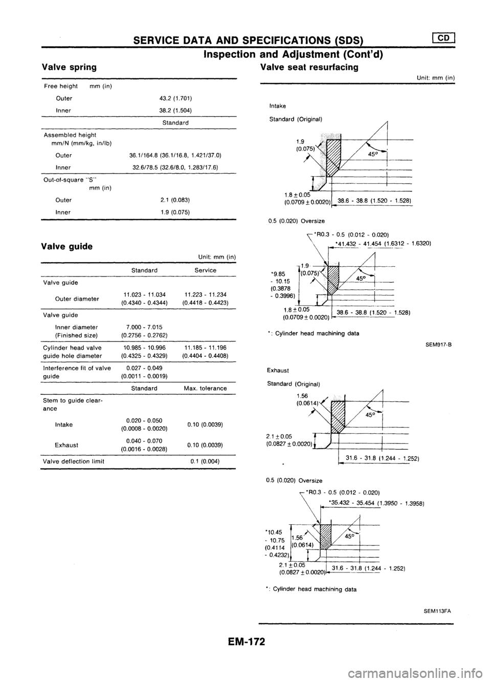
Valvespring SERVICE
DATAANDSPECIFICATIONS (50S)
Inspection andAdjustment (Cont'd)
Valve seatresurfacing
Unit:mm(in)
Free height mm(in)
Outer
Inner
Assembled height
mm/N (mm/kg, in/lb)
Outer Inner
Out-of-square "S"
mm (in)
Outer
Inner
43.2
(1.701)
38.2 (1.504)
Standard
36.1/164.8 (36.1/16.8,1.421/37.0)
32.6/78.5 (32.6/8.0, 1.283/17.6)
2.1 (0.083)
1.9 (0.075)
Intake
Standard (Original)
1.8:t 0.05
(0.0709:t 0.0020) 38.6-38.8 (1.520 -1.528)
0.5 (0.020)
Oversize
Exhaust
2.1 :to.05
(0.0827 :t0.0020)
Valve
guide
Valve guide
Outer diameter
Valve guide
Inner diameter
(Finished size)
Cylinder headvalve
guide holediameter
Interference fitofvalve
guide
Stem toguide clear-
ance
Intake
Exhaust Standard
11.023 -11.034
(0.4340 -0.4344)
7.000 -7.015
(0.2756 -0.2762)
10.985 -10.996
(0.4325 -0.4329)
0.027 -0.049
(0.0011 -0.0019)
Standard
0.020 -0.050
(0.0008 -0.0020)
0.040 -0.070
(0.0016 -0.0028)
Unit:
mm(in)
Service
11.223 -11.234
(0.4418 -0.4423)
11.185 -11.196
(0.4404 -0.4408)
Max. tolerance
0.10 (0.0039)
0.10 (0.0039) '\
'RO.3 -0.5 (0.012 -0.020)
. '41.4_~- 4!:.,454(1.~312 -16320)
'9.85
- 10.15
(0.3878
- 0.3996)
1.8:t0.05 38.6-38.8 (1.520 -1.528)
(0.0709:t 0.0020)
': Cylinder headmachining data
SEM917-B
Standard (Original)
Valve deflection limit
0.1(0.004) 31.6
-31.8 (1.244 -1.252)
31.6 -31.8 (1.244 -1.252)
0.5
(0.020)
Oversize
,- 'RO.3 -0.5 (0.012 -0.020)
r
'35.432 -35.454 (1.3950 -1.3958)
'10.45
- 10.75
(0.4114 (0.0614)
- 0.4232)
2.1:t0.05
(0.0827 :t0.0020)
Cylinder headmachining data
SEM113FA
EM-172
Page 1393 of 1701
IDENTIFICATIONINFORMATION
Dimensions SedanUnit:
mm(in) •
Hatchback
Overall length
Overall width
Overall height
Front tread
Rear tread
Wheelbase 4,320
(170.1)
1,690 (66.5)
1,395 (54.9)
1,480 (58.3)* 1
1,470 (57.9)*2
1,445 (56.9)*1
1,435 (56.5)*2
2,535 (99.8) 4,120
(162.2)
*1: For models with13-inch roadwheels
*2: For models with14-inch or15-inch roadwheels
Wheels andTires
Steel 13x5J 14x5-1/2JJ
-
Road Offset
mm(in) 35(1.38) 40(1.57)
wheel Aluminum 13x5J 14
x5-1/2JJ 15x6J
Offset mm(in)
35(1.38) 40
(1.57) 40(1.57)
175170R1382S 175/65R1482H
195/55R1584V
Conventional
185/65R1486H
Tire size 165SR13
Spare Conventional
Conventional Conventional
GI-39
Page 1544 of 1701

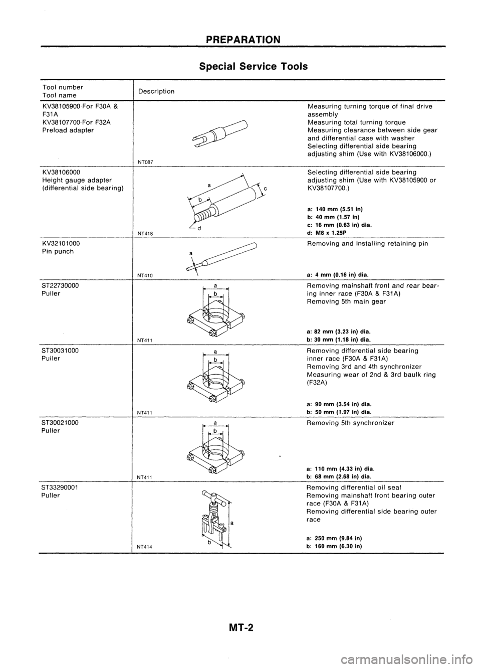
Toolnumber
Tool name
KV38105900.For F30A
&
F31A KV38107700.For F32A
Preload adapter Description
NT087 PREPARATION
Special Service Tools
Measuring turningtorqueoffinal drive
assembly Measuring totalturning torque
Measuring clearancebetweensidegear
and differential casewithwasher
Selecting differential sidebearing
adjusting shim(UsewithKV38106000.)
KV38106000
Height gaugeadapter
(differential sidebearing)
KV32101000
Pin punch
8T22730000 Puller
8T30031 000
Puller
8T30021 000
Puller
ST33290001 Puller
NT418
NT410
NT411
NT411
NT411
NT414
Selecting
differential sidebearing
adjusting shim(UsewithKV38105900 or
KV381 07700.)
a: 140 mm (5.51 in)
b: 40
mm
(1.57
in)
c: 16 mm (0.63 in)dia.
d: M8
x
1.25P
Removing andinstalling retainingpin
a: 4mm (0.16 in)dia.
Removing mainshafl
front
andrear bear-
ing inner race(F30A
&
F31 A)
Removing 5thmain gear
a: 82 mm (3.23 in)dia.
b: 30 mm (1.18 in)dia.
Removing differential sidebearing
inner race(F30A
&
F31A)
Removing 3rdand 4thsynchronizer
Measuring wearof2nd
&
3rd baulk ring
(F32A)
a: 90 mm (3.54 in)dia.
b: 50mm (1.97 in)dia.
Removing 5thsynchronizer
a: 110 mm (4.33 in)dia.
b: 68 mm (2.68 in)dia.
Removing differential oilseal
Removing mainshaflfrontbearing outer
race (F30A
&
F31A)
Removing differential sidebearing outer
race
a:
250
mm
(9.84
in)
b: 160 mm (6.30 in)
MT-2
Page 1592 of 1701
Strikinglever
Reverse brakeearn REPAIR
FORCOMPONENT PARTS
Shift Control Components (Cont'd)
SMT099C I
RS5F32A
I
ADJUSTMENT OFINPUT SHAFT BRAKING MECHANISM
1. Install striking lever
&
rod, striking interlock assembly and
control bracket onclutch housing exactly.
• When installing controlbracket onclutch housing, assure
protrusion beneathbracketiscorrectly seated.
SMT774B
Height
gauge
2.
Measure maximum height"H"while shifting fromneutral to
reverse position.
Maximum height
"H":
67.16 -67.64
mm
(2.6441 .2.6630
in)
Control bracket
fitting surface 1
st
&
2nd shifter
~
Reverse brakecarn
SMT728B
MT-SO
Page 1608 of 1701
Unit:mm(in)
2.9 -6.9 (30-70, 26-61)
0.25
-0.30 (0.0098 -0.0118)
Differential
sidebearing
Final drive
Bearing
preload(Reused bearing)
Turning torque(Newbearing)
Unit:N'm(kg-cm, in-Ib)
Reverse brakecam
H SERVICE
DATAANDSPECIFICATIONS (SDS)
Inspection andAdjustment -RS5F32A (Cont'd)
INPUT SHAFT BRAKING MECHANISM AVAILABLESHIMS
DIFFERENTIAL SIDEBEARING
PRELOAD ANDADJUSTING SHIM
Reverse
brakeearn
SMT735B
Maximum height"H"between
the control bracket fittingsur-
face and1-2shiller 67.16
-67.64
(2.6441 -2.6330) Differential
sidebearing adjusting shims
mm (in)
Clearance "C"between
reverse brakecarnandstriking
lever c
SMT736B
0.05 -0.125
(0.0020 -0.0049) Thickness
mm(in)
Partnumber
0.44 (0.0173)
38454-M8000
0.48 (0.0189)
38454-M8001
0.56 (0.0220) 38454-M8003
0.60 (0.0236) 38454-M8004
0.64 (0.0252) 38454-M8005
0.68 (0.0268) 38454-M8006
0.72 (00283) 38454-M8007
0.76 (00299)
38454-M8008
0.80 (0.0315)
38454-M8009
0.84 (0.0331) 38454-M8010
0.88 (0.0346) 38454-M8011
mrn (in)
MT-66
Page 1613 of 1701

ON-VEHICLESERVICE
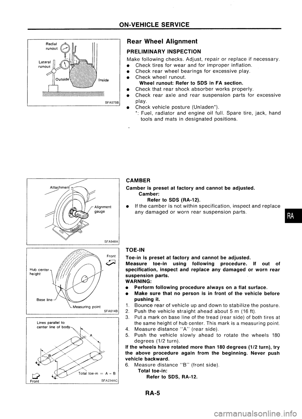
Rear Wheel Alignment
PRELIMINARY INSPECTION
Make following checks.Adjust,repairorreplace ifnecessary.
• Check tiresforwear andforimproper inflation.
• Check rearwheel bearings forexcessive play.
• Check wheelrunout.
Wheel runout: RefertoSOS inFA section.
• Check thatrear shock absorber worksproperly.
• Check rearaxleandrear suspension partsforexcessive
SFA575B
play.
• Check vehicle posture (Unladen*).
*: Fuel, radiator andengine oilfull. Spare tire,jack, hand
tools andmats indesignated positions.
•
CAMBER
Camber ispreset atfactory andcannot beadjusted.
Camber: Refer toSOS (RA-12).
• Ifthe camber isnot within specification, inspectandreplace
any damaged orworn rearsuspension parts.
TOE-IN
Toe-in ispreset atfactory andcannot beadjusted.
Measure toe-inusingfollowing procedure. Ifout of
specification, inspectandreplace anydamaged orworn rear
suspension parts.
WARNING:
• Perform following procedure alwaysonaflat surface.
• Make surethatnoperson isin front ofthe vehicle before
pushing it.
1. Bounce rearofvehicle upand down tostabilize theposture.
2. Push thevehicle straight aheadabout5m (16
ft).
3. Putamark onbase lineofthe tread (rearside) ofboth tires at
the same height ofhub center. Thismark isameasuring point.
4. Measure distance"A"(rear side).
5. Push thevehicle slowlyaheadtorotate thewheels 180
degrees (1/2turn).
If the wheels haverotated morethan180degrees (1/2turn), try
the above procedure againfromthebeginning. Neverpush
vehicle backward.
6. Measure distance"B"(front side).
Total toe-in:
Refer toSOS, RA-12.
Front
SFA948A
SFA614B
SFA234AC
Lines
parallel to
center lineofbOdY~
Q
Front
Hub
center
height
RA-5