Page 1225 of 1701
ENGINEREMOVAL
mJ
Removal (Cont'd)
• Disconnect controlrodand support rodfrom transaxle.
(M/T
models)
Control rod:
to:J:
14-18 N.m (1.4-1.8 kg-m, 10-13 ft-Ib)
Support rod:
to:J:
35-47 N.m (3.6-4.8 kg-m, 26-35 ft-Ib)
• Disconnect controlcablefromtransaxle.
(A/Tmodels)
• Center member
• Front exhaust tube
• Stabilizer
• Cooling fan
• Radiator
• Cylinder headfrontmounting bracket
• Remove airduct anddisconnect wires,harness, pipes,
hoses andsoon.
8. Lift upengine slightly anddisconnect orremove allengine
mountings.
When liftingengine, becareful nottohit itagainst adjacent
parts, especially againstbraketubesandbrake master cylin-
der.
9. Remove enginewithtransaxle asshown.
Installation
When installing theengine, adjusttheheight ofbuffer rodas
shown. (ForM/T)
• Installation isthe reverse orderofremoval.
EM-46
Page 1229 of 1701
SEM003FCYLINDER
BLOCK
Inspection (Cont'd)
Feeler gauge Straightedge
SEM102F
I
I
,
,
!
,
A
X-V
B
Unit:
mm
(In)
SEM166DA CYLINDER
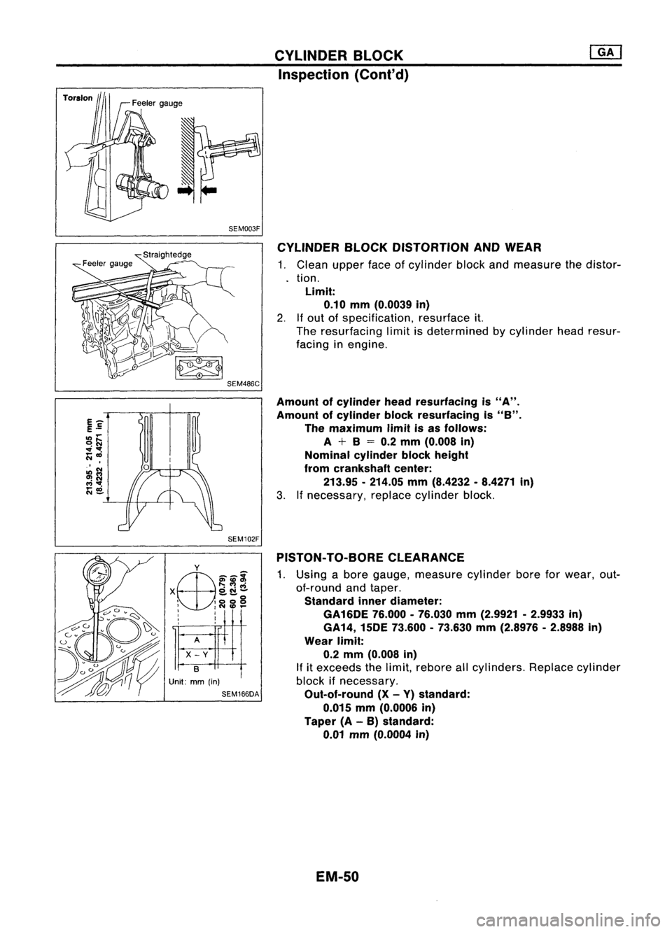
BLOCKDISTORTION ANDWEAR
1. Clean upperfaceofcylinder blockandmeasure thedistor-
tion.
Limit: 0.10 mm(0.0039 in)
2. Ifout ofspecification, resurface
it.
The resurfacing limitisdetermined bycylinder headresur-
facing inengine.
Amount ofcylinder headresurfacing is
"A".
Amount ofcylinder blockresurfacing is
"B".
The maximum limitisas follows:
A
+
B
= 0.2 mm (0.008 in)
Nominal cylinderblockheight
from crankshaft center:
213.95 -214.05 mm(8.4232 .8.4271 in)
3. Ifnecessary, replacecylinder block.
PISTON- TO-BORE CLEARANCE
1. Using abore gauge, measure cylinderboreforwear, out-
of-round andtaper.
Standard innerdiameter:
GA16DE 76.000-76.030 mm(2.9921 -2.9933 in)
GA14, 15DE73.600 -73.630 mm(2.8976 -2.8988 in)
Wear limit:
0.2 mm (0.008 in)
If itexceeds thelimit, rebore allcylinders. Replacecylinder
block ifnecessary.
Out-of-round (X-Y) standard:
0.015 mm(0.0006 in)
Taper (A-B) standard:
0.01 mm(0.0004 in)
EM-50
Page 1267 of 1701
SEM925CCYLINDER
HEAD
Disassembly (Cont'd)
12. Remove valveoilseal with asuitable tool.
Inspection
CYLINDER HEADDISTORTION
. Head surface flatness:
Standard Less than0.03mm(0.0012 in)
Limit
0.1 mm (0.004 in)
If beyond thespecified limit,replace orresurface.
Resurfacing limit:
The resurfacing limitofcylinder headisdetermined bythe cyl-
inder block resurfacing inan engine.
Amount ofcylinder headresurfacing is
"A".
Amount ofcylinder blockresurfacing is
"B".
The maximum limitisas follows:
A
+
B
=
0.2 mm (0.008 in)
After resurfacing cylinderhead,check thatcamshaft rotates
freely byhand. Ifresistance isfelt, cylinder headmustbe
replaced.
Nominal cylinderheadheight:
136.9 -137.1 mm(5.390 -5.398 in)
CAMSHAFT VISUALCHECK
Check camshaft forscratches, seizureandwear.
CAMSHAFT RUNOUT
1. Measure camshaft runoutatthe center journal.
Runout (Totalindicator reading):
Standard Less than0.02mm(0.0008 in)
Limit
0.1 mm (0.004 in)
2. Ifitexceeds thelimit, replace camshaft.
EM-88
Page 1268 of 1701
SEM929CCYLINDER
HEAD ~
Inspection (Cont'd)
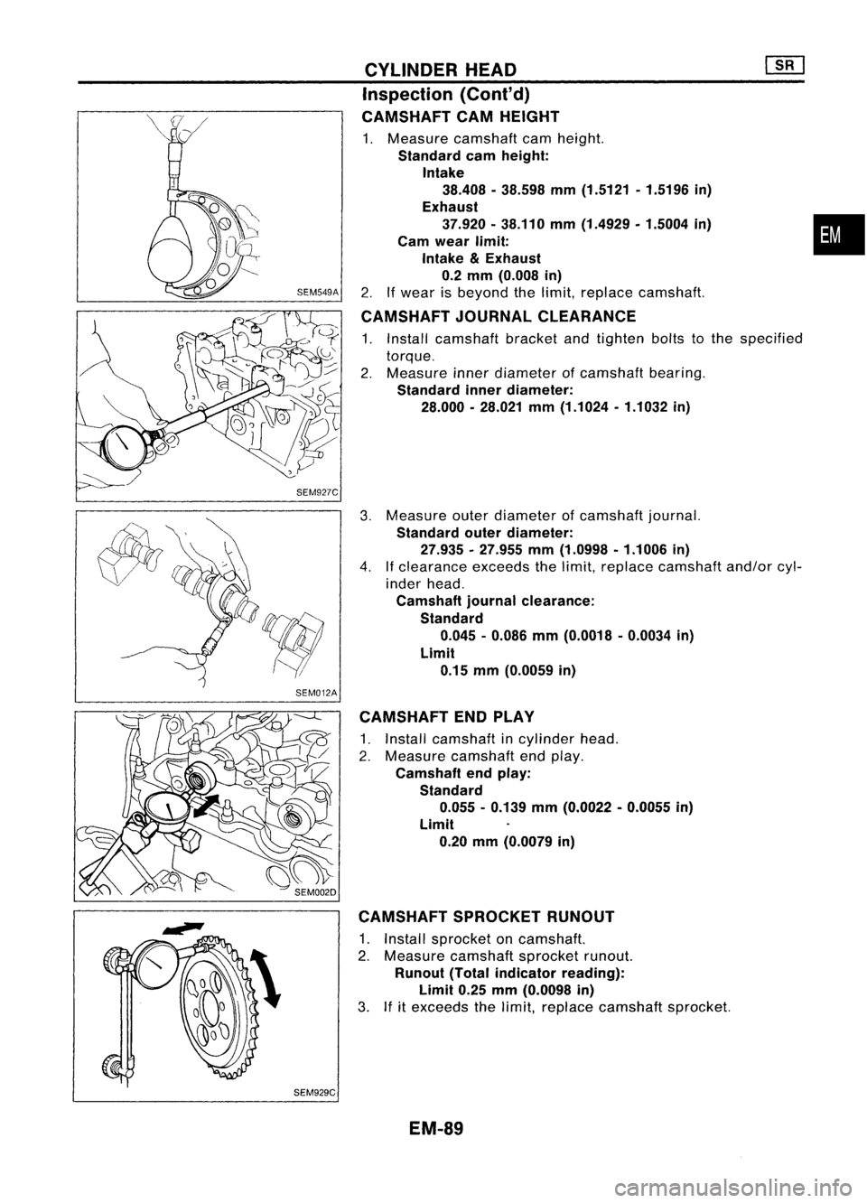
CAMSHAFT CAMHEIGHT
1. Measure camshaft camheight.
Standard camheight:
Intake 38.408 -38.598 mm(1.5121 .1.5196 in)
Exhaust 37.920 •38.110 mm(1.4929. 1.5004in)
Cam wear limit:
Intake
&
Exhaust
0.2 mm (0.008 in)
2. Ifwear isbeyond thelimit, replace camshaft.
CAMSHAFT JOURNALCLEARANCE
1. Install camshaft bracketandtighten boltstothe specified
torque.
2. Measure innerdiameter ofcamshaft bearing.
Standard innerdiameter:
28.000 -28.021 mm(1.1024 -1.1032 in)
Measure outerdiameter ofcamshaft journal.
Standard outerdiameter:
27.935 .27.955 mm(1.0998 -1.1006 in)
If clearance exceedsthelimit, replace camshaft and/orcyl-
inder head.
Camshaft journalclearance:
Standard 0.045 -0.086 mm(0.0018 .0.0034 in)
Limit 0.15 mm(0.0059 in)
CAMSHAFT ENDPLAY
1. Install camshaft incylinder head.
2. Measure camshaft endplay.
Camshaft endplay:
Standard 0.055. 0.139mm(0.0022 -0.0055 in)
Limit 0.20 mm(0.0079 in)
CAMSHAFT SPROCKETRUNOUT
1. Install sprocket oncamshaft.
2. Measure camshaft sprocketrunout.
Runout (Totalindicator reading):
Limit 0.25mm(0.0098 in)
3. Ifitexceeds thelimit, replace camshaft sprocket.
EM-89
•
Page 1271 of 1701
T(Margin thickness)
~I
r
nw
a
III' ~
D
L
-l
d
SEM892B
SEM188A CYLINDER
HEAD
Inspection (Cont'd)
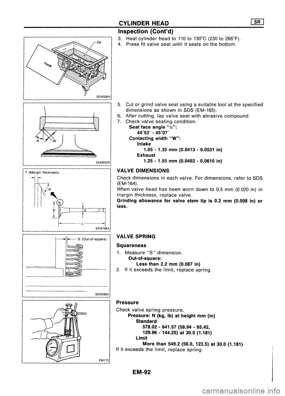
3. Heat cylinder headto110 to130°C (230to266°F).
4. Press fitvalve seatuntil itseats onthe bottom.
5. Cut orgrind valve seatusing asuitable toolatthe specified
dimensions asshown inSDS (EM-165).
6. After cutting, lapvalve seatwithabrasive compound.
7. Check valveseating condition.
Seat faceangle
"u":
44°53' -45°07'
Contacting width
"W":
Intake 1.05 -1.35 mm(0.0413 -0.0531 in)
Exhaust
1.25 -1.55 mm(0.0492 -0.0610 in)
VALVE DIMENSIONS
Check dimensions ineach valve. Fordimensions, refertoSDS
(EM-164).
When valveheadhasbeen worn down to0.5 mm (0.020 in)in
margin thickness, replacevalve.
Grinding allowance forvalve stemtipis0.2 mm (0.008 in)or
less.
SEM288A VALVE
SPRING
Squareness
1. Measure "S"dimension.
Out-of-square:
Less than2.2mm (0.087 in)
2. Ifitexceeds thelimit, replace spring.
EM113 Pressure
Check valvespring pressure.
Pressure: N(kg, Ib)atheight mm(in)
Standard
578.02 -641.57 (58.94-65.42,
129.96 -144.25) at30.0 (1.181)
Limit
More than549.2 (56.0, 123.5) at30.0 (1.181)
If itexceeds thelimit, replace spring.
EM-92
Page 1279 of 1701
SEM312DENGINE
REMOVAL
Removal (Cont'd)
12. Remove enginewithtransaxle asshown.
Installation
1. Install engine mounting bracketandfixing bolts.
Be sure thatinsulators arecorrectly positioned onthe brack-
ets.
2. Carefully lowertheengine ontoengine mounting insulators.
When installing theengine, adjusttheheight ofthe engine
mounting asshown. (ForM/T)
3. Installation isinthe reverse orderofremoval.
EM-100
Page 1283 of 1701
SEM123CCYLINDER
BLOCK ~
Inspection (Cont'd)
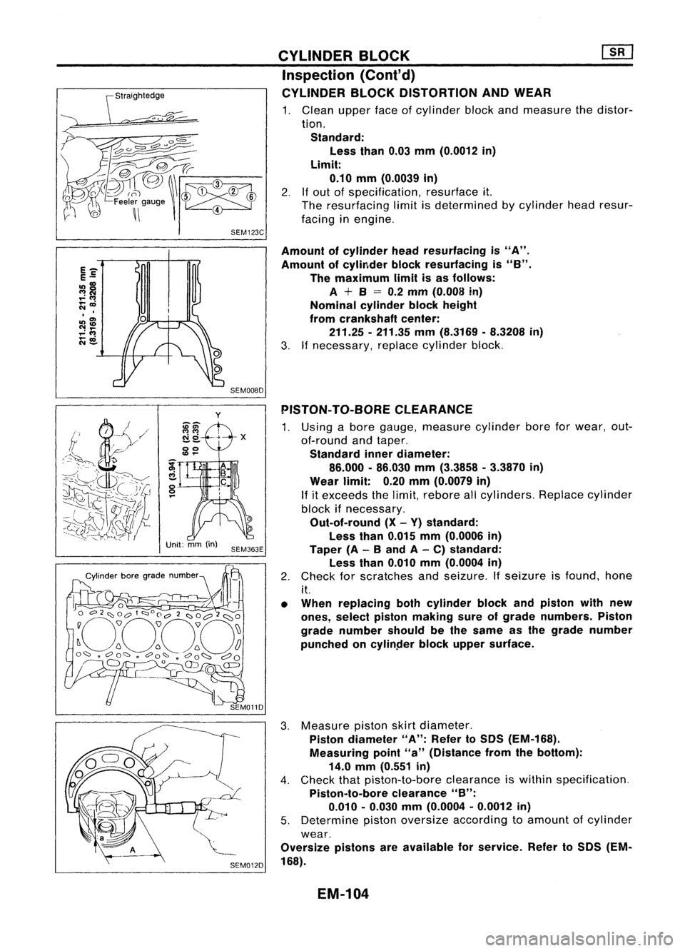
CYLINDER BLOCKDISTORTION ANDWEAR
1. Clean upperfaceofcylinder blockandmeasure thedistor-
tion. Standard: Less than0.03mm(0.0012 in)
Limit: 0.10 mm(0.0039 in)
2.
If
out ofspecification, resurfaceit.
The resurfacing limitisdetermined bycylinder headresur-
facing inengine.
SEM008D
Amount
ofcylinder headresurfacing is"A".
Amount ofcylinder blockresurfacing is
"8".
The maximum limitisas follows:
A
+
8
=
0.2 mm (0.008 in)
Nominal cylinderblockheight
from crankshaft center:
211.25 -211.35 mm(8.3169 -8.3208 in)
3. Ifnecessary, replacecylinder block.
y
ii-El)'
N 0+ -X
--
00
Unit: mm(in)
SEM363E PISTON-
TO-BORE CLEARANCE
1. Using abore gauge, measure cylinderboreforwear, out-
of-round andtaper.
Standard innerdiameter:
86.000 -86.030 mm(3.3858 -3.3870 in)
Wear limit: 0.20mm(0.0079 in)
If
itexceeds thelimit, rebore allcylinders. Replacecylinder
block ifnecessary.
Out-of-round (X-Y) standard:
Less than0.015 mm(0.0006 in)
Taper (A-
8
and A-C) standard:
Less than0.010 mm(0.0004 in)
2. Check forscratches andseizure. Ifseizure isfound. hone
it.
• When replacing bothcylinder blockandpiston withnew
ones, select piston making sureofgrade numbers. Piston
grade number shouldbethe same asthe grade number
punched oncylinper blockupper surface.
3. Measure pistonskirtdiameter.
Piston diameter "A":Refer toSDS (EM-168).
Measuring point"a"(Distance fromthebottom):
14.0 mm(0.551 in)
4. Check thatpiston-to-bore clearanceiswithin specification.
Piston-to-bore clearance"B":
0.010 -0.030 mm(0.0004 -0.0012 in)
5. Determine pistonoversize according toamount ofcylinder
wear.
Oversize pistonsareavailable forservice. RefertoSDS (EM-
168).
EM-104
Page 1309 of 1701
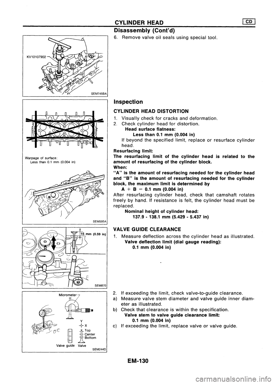
Warpageofsurface:
Less than0.1mm (0.004 in)
SEM595A
_ Mic~rmeter
..;- @f
l ~
--I\"
Y
'~~':-- +x
'~o
rA1-
Center
[gJ
Bottom
Valve guide Valve
SEM244D CYLINDER
HEAD
Disassembly (Cont'd)
6. Remove valveoilseals usingspecial tool.
Inspection
CYLINDER HEADDISTORTION
1. Visually checkforcracks anddeformation.
2. Check cylinder headfordistortion.
Head surface flatness:
Less than0.1mm (O.004 in)
If beyond thespecified limit,replace orresurface cylinder
head.
Resurfacing limit:
The resurfacing limitofthe cylinder headisrelated tothe
amount ofresurfacing ofthe cylinder block.
When:
"A"
isthe amount ofresurfacing neededforthe cylinder head
and
"8"
isthe amount ofresurfacing neededforthe cylinder
block, themaximum limitisdetermined by
A + 8= 0.1 mm (O.004 in)
After resurfacing cylinderhead,check thatcamshaft rotates
freely byhand. Ifresistance isfelt, thecylinder headmustbe
replaced.
Nominal heightofcylinder head:
137.9. 138.1mm(5.429 .5.437 in)
VALVE GUIDECLEARANCE
1. Measure deflection acrossthecylinder headasillustrated.
Valve deflection limit(dial gauge reading):
0.1 mm (0.004 in)
2. Ifexceeding thelimit, check valve-to-guide clearance.
a) Measure valvestemdiameter andvalve guide innerdiam-
eter asillustrated.
b) Check thatclearance iswithin thespecification .
Valve stemtovalve guide clearance limit:
0.1 mm (O.004 in)
c) Ifexceeding thelimit, replace valveorvalve guide.
EM-130