Page 885 of 1771
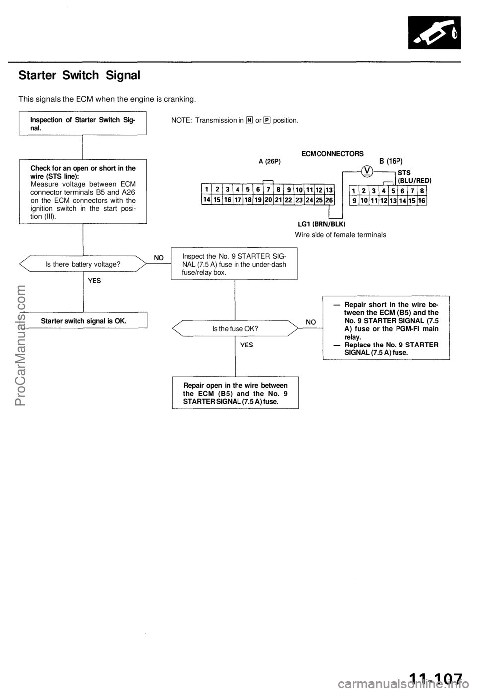
Starter Switc h Signa l
This signal s th e EC M whe n th e engin e is cranking .
NOTE: Transmissio n in o r position .
A (26P)ECM CONNECTOR S
Wir e sid e o t femal e terminal s
I s ther e batter y voltage ?
Is th e fus e OK ? Repai
r shor t i n th e wir e be -
twee n th e EC M (B5 ) an d th eNo . 9 STARTE R SIGNA L (7. 5
A ) fus e o r th e PGM-F I mai n
relay .Replac e th e No . 9 STARTE R
SIGNA L (7. 5 A ) fuse .
B (16P )
Inspectio n o f Starte r Switc h Sig -nal.
Chec k fo r a n ope n o r shor t i n th e
wir e (ST S line) :
Measur e voltag e betwee n EC M
connecto r terminal s B 5 an d A2 6on th e EC M connector s wit h th e
ignitio n switc h i n th e star t posi -
tion (III) .
Starte r switc h signa l i s OK . Inspec
t th e No . 9 STARTE R SIG -
NA L (7. 5 A ) fus e in th e under-das h
fuse/rela y box .
Repai r ope n in th e wir e betwee n
the EC M (B5 ) and th e No . 9STARTE R SIGNA L (7. 5 A ) fuse .
ProCarManuals.com
Page 887 of 1771
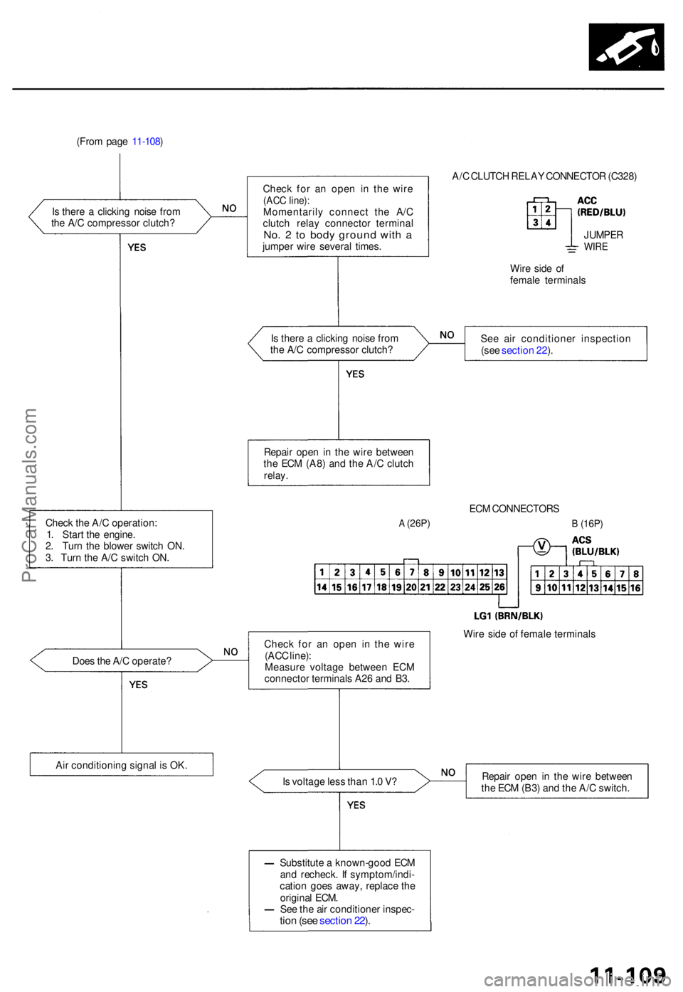
(From pag e 11-108 )
I s ther e a clickin g nois e fro m
th e A/ C compresso r clutch ?
Chec k th e A/ C operation :
1 . Star t th e engine .
2 . Tur n th e blowe r switc h ON .
3 . Tur n th e A/ C switc h ON .
Doe s th e A/ C operate ?
Ai r conditionin g signa l i s OK . Chec
k fo r a n ope n i n th e wire
(AC C line) :Momentaril y connec t th e A/ C
clutc h rela y connecto r termina l
No. 2 to bod y groun d wit h ajumpe r wir e severa l times . A/
C CLUTC H RELA Y CONNECTO R (C328 )JUMPE RWIRE
Wire sid e o f
femal e terminal s
I s ther e a clickin g nois e fro m
th e A/ C compresso r clutch ? Se
e ai r conditione r inspectio n
(se e sectio n 22 ).
Repai r ope n i n th e wir e betwee n
th e EC M (A8 ) an d th e A/ C clutc h
relay.
ECM CONNECTOR S
A (26P)B (16P)
Chec k fo r a n ope n i n th e wir e
(AC C line) :
Measur e voltag e betwee n EC M
connecto r terminal s A2 6 an d B3 . Wir
e sid e o f femal e terminal s
I s voltag e les s tha n 1. 0 V ? Repai
r ope n i n th e wir e betwee n
th e EC M (B3 ) an d th e A/ C switch .
Substitut e a known-goo d EC M
an d recheck . I f symptom/indi -
catio n goe s away , replac e th e
origina l ECM .
Se e th e ai r conditione r inspec -
tion (se e sectio n 22 ).
ProCarManuals.com
Page 902 of 1771
Fuel Supply System
System Description
The fuel supply system consists of a fuel tank, in-tank
high pressure fuel pump, PGM-FI main relay, fuel filter,
fuel pressure regulator, fuel injectors, and fuel delivery
and return lines. This system delivers pressure-regulat-
ed fuel to the fuel injectors and cuts the fuel delivery
when the engine is not running.
11-124ProCarManuals.com
Page 914 of 1771
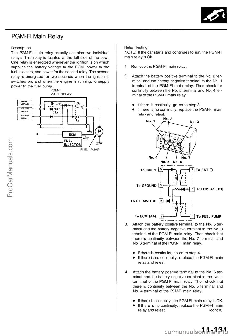
PGM-FI Main Relay
Description
The PGM-FI main relay actually contains two individual
relays. This relay is located at the left side of the cowl.
One relay is energized whenever the ignition is on which
supplies the battery voltage to the ECM, power to the
fuel injectors, and power for the second relay. The second
relay is energized for two seconds when the ignition is
switched on, and when the engine is running, to supply
power to the fuel pump.
PGM-FI
MAIN RELAY
FUEL PUMP
Relay Testing
NOTE: If the car starts and continues to run, the PGM-FI
main relay is OK.
1. Remove the PGM-FI main relay.
2.
Attach the battery positive terminal to the No. 2 ter-
minal and the battery negative terminal to the No. 1
terminal of the PGM-FI main relay. Then check for
continuity between the No. 5 terminal and No. 4 ter-
minal of the PGM-FI main relay.
If there is continuity, go on to step 3.
If there is no continuity, replace the PGM-FI main
relay and retest.
3. Attach the battery positive terminal to the No. 5 ter-
minal and the battery negative terminal to the No. 3
terminal of the PGM-FI main relay. Then check that
there is continuity between the No. 7 terminal and
No. 6 terminal of the PGM-FI main relay.
If there is continuity, go on to step 4.
If there is no continuity, replace the PGM-FI main
relay and retest.
4. Attach the battery positive terminal to the No. 6 ter-
minal and the battery negative terminal to the No. 1
terminal of the PGM-FI main relay. Then check that
there is continuity between the No. 5 terminal and
No. 4 terminal of the PGM-FI main relay.
If there is continuity, the PGM-FI main relay is OK.
If there is no continuity, replace the PGM-FI main
relay and retest.ProCarManuals.com
Page 915 of 1771
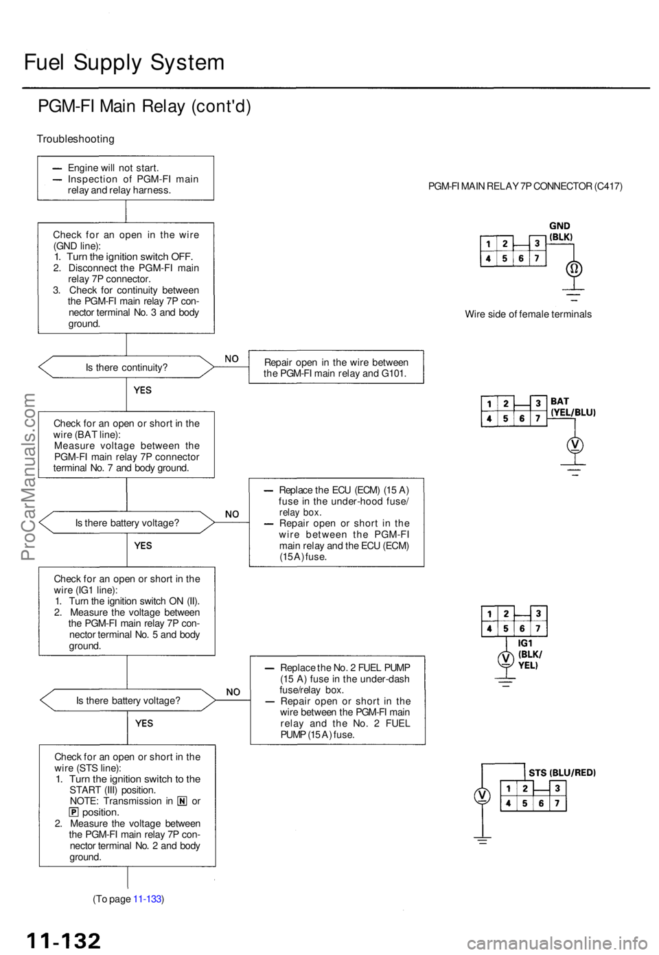
Fuel Suppl y Syste m
PGM-F I Mai n Rela y (cont'd )
Troubleshootin g
Engine wil l no t start .
Inspectio n o f PGM-F I mai n
rela y an d rela y harness .
Chec k fo r a n ope n i n th e wir e
(GN D line) :
1. Tur n th e ignitio n switc h OFF .2. Disconnec t th e PGM-F I mai n
rela y 7 P connector .
3 . Chec k fo r continuit y betwee n
th e PGM-F I mai n rela y 7 P con -
necto r termina l No . 3 an d bod y
ground .
I s ther e continuity ?
Chec k fo r a n ope n o r shor t i n th e
wir e (BA T line) :
Measur e voltag e betwee n th e
PGM-F I mai n rela y 7 P connecto r
termina l No . 7 an d bod y ground .
I s ther e batter y voltage ?
Chec k fo r a n ope n o r shor t i n th e
wir e (IG 1 line) :
1 . Tur n th e ignitio n switc h O N (II) .
2 . Measur e th e voltag e betwee n
th e PGM-F I mai n rela y 7 P con -
necto r termina l No . 5 an d bod y
ground .
I s ther e batter y voltage ?
Chec k fo r a n ope n o r shor t i n th e
wir e (ST S line) :
1. Tur n th e ignitio n switc h to th eSTAR T (III ) position .NOTE: Transmissio n i n o rposition .2. Measur e th e voltag e betwee n
th e PGM-F I mai n rela y 7 P con -
necto r termina l No . 2 an d bod y
ground .
(T o pag e 11-133 ) PGM-F
I MAI N RELA Y 7 P CONNECTO R (C417 )
Wir e sid e o f femal e terminal s
Repai r ope n in th e wir e betwee n
th e PGM-F I mai n rela y an d G101 .
Replac e th e EC U (ECM ) (1 5 A )
fus e i n th e under-hoo d fuse /
relay box .Repai r ope n o r shor t i n th e
wir e betwee n th e PGM-F I
mai n rela y an d th e EC U (ECM )
(1 5 A ) fuse .
Replac e th e No . 2 FUE L PUM P
(1 5 A ) fus e in th e under-das h
fuse/rela y box .
Repai r ope n o r shor t i n th e
wir e betwee n th e PGM-F I mai n
rela y an d th e No . 2 FUE L
PUM P (1 5 A ) fuse .
ProCarManuals.com
Page 916 of 1771
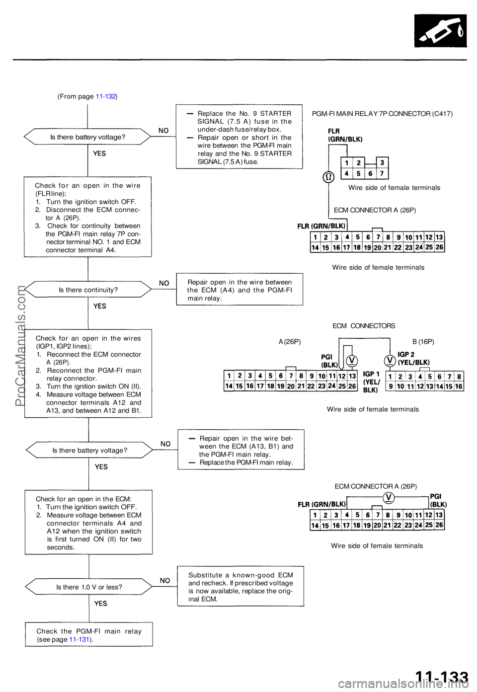
(From pag e 11-132 )
I s ther e 1. 0 V or less ?
Replac e th e No . 9 STARTE RSIGNAL (7. 5 A ) fus e i n th e
under-das h fuse/rela y box .
Repai r ope n o r shor t i n th ewir e betwee n th e PGM-F I mai n
rela y an d th e No . 9 STARTE R
SIGNA L (7. 5 A ) fuse . PGM-F
I MAI N RELA Y 7 P CONNECTO R (C417 )
Wir e sid e o f femal e terminal s
Repai r ope n i n th e wir e betwee n
th e EC M (A4 ) an d th e PGM-F I
mai n relay .
ECM CONNECTOR S
Wir e sid e o f femal e terminal s
Repai r ope n i n th e wir e bet -
wee n th e EC M (A13 , B1 ) an d
th e PGM-F I mai n relay .
Replac e th e PGM-F I mai n relay .
ECM CONNECTO R A (26P )
Wir e sid e o f femal e terminal s
Substitut e a known-goo d EC M
an d recheck . I f prescribe d voltag e
i s no w available , replac e th e orig -
ina l ECM .
Chec k th e PGM-F I mai n rela y
(se e pag e 11-131 ).
Chec
k fo r a n ope n in th e ECM :
1. Tur n th e ignitio n switc h OFF .2. Measur e voltag e betwee n EC M
connecto r terminal s A 4 an d
A12 whe n th e ignitio n switc his firs t turne d O N (II ) fo r tw o
seconds .
I
s ther e batter y voltage ?
Chec
k fo r a n ope n i n th e wire s
(IGP1 , IGP 2 lines) :
1 . Reconnec t th e EC M connecto r
A (26P) .2. Reconnec t th e PGM-F I mai n
rela y connector .
3 . Tur n th e ignitio n switc h O N (II) .
4 . Measur e voltag e betwee n EC M
connecto r terminal s A1 2 an d
A13 , an d betwee n A1 2 an d B1 .
I
s ther e continuity ? EC
M CONNECTO R A (26P )
B (16P)A (26P )
Wire sid e o f femal e terminal s
Chec
k fo r a n ope n i n th e wir e
(FL R line) :
1 . Tur n th e ignitio n switc h OFF .
2 . Disconnec t th e EC M connec -
tor A (26P) .3. Chec k fo r continuit y betwee n
th e PGM-F I mai n rela y 7 P con -
necto r termina l NO . 1 an d EC M
connecto r termina l A4 .
Is ther e batter y voltage ?
ProCarManuals.com
Page 917 of 1771
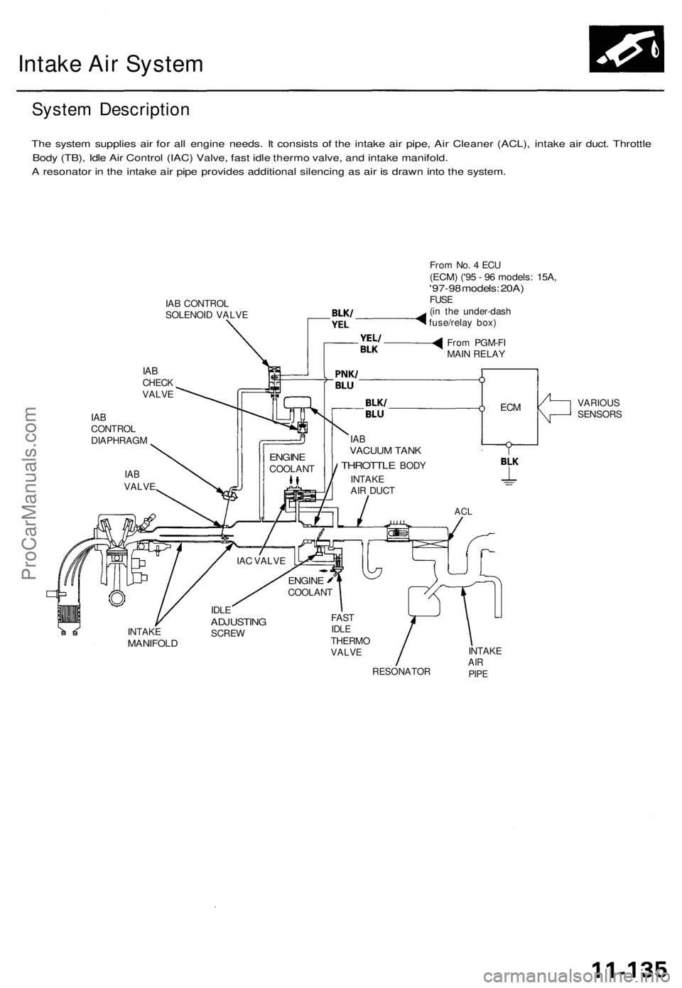
Intake Air System
System Description
The system supplies air for all engine needs. It consists of the intake air pipe, Air Cleaner (ACL), intake air duct. Throttle
Body (TB), Idle Air Control (IAC) Valve, fast idle thermo valve, and intake manifold.
A resonator in the intake air pipe provides additional silencing as air is drawn into the system.
IAB CONTROL
SOLENOID VALVE
IAB
CHECK
VALVE
IAB
CONTROL
DIAPHRAGM
From No. 4 ECU
(ECM) ('95 - 96 models: 15A,
'97-98 models: 20A)
FUSE
(in the under-dash
fuse/relay box)
From PGM-FI
MAIN RELAY
VARIOUS
SENSORS
IAB
VACUUM TANK
THROTTLE
BODY
INTAKE
AIR DUCT
ACL
INTAKE
MANIFOLD
IDLE
ADJUSTING
SCREW
FAST
IDLE
THERMO
VALVE
RESONATOR
INTAKE
AIR
PIPE
IAC VALVE
ENGINE
COOLANT
ENGINE
COOLANT
IAB
VALVE
ECMProCarManuals.com
Page 923 of 1771
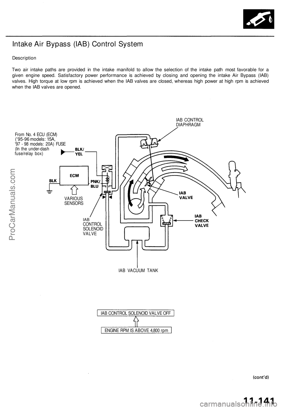
Intake Air Bypass (IAB) Control System
Description
Two air intake paths are provided in the intake manifold to allow the selection of the intake path most favorable for a
given engine speed. Satisfactory power performance is achieved by closing and opening the intake Air Bypass (IAB)
valves. High torque at low rpm is achieved when the IAB valves are closed, whereas high power at high rpm is achieved
when the IAB valves are opened.
IAB CONTROL
DIAPHRAGM
From No. 4 ECU (ECM)
('95-96 models: 15A,
'97 - 98 models: 20A) FUSE
(In the under-dash
fuse/relay box)
VARIOUS
SENSORS
IAB
CONTROL
SOLENOID
VALVE
IAB VACUUM TANK
IAB CONTROL SOLENOID VALVE OFF
ENGINE RPM IS ABOVE 4,800 rpmProCarManuals.com