Page 578 of 1771
Relay an d Contro l Uni t Location s
Dashboar d (cont'd )
ProCarManuals.com
Page 581 of 1771
Power Relay s
Relay Tes t
NOTE : Refe r t o page 23-62 in the '9 5 - 9 6 Acur a 2.5T L
Service Manual, P/ N 61SW500 , fo r th e item s no t shown
in this sub-section .
Normally-ope n type :
1 . Chec k fo r continuit y betwee n th e terminals .
• Ther e shoul d b e continuit y betwee n th e No . 1 an d
No . 3 terminal s whe n powe r an d groun d ar e con -
necte d to th e No . 2 an d No . 4 terminals .
• Ther e shoul d b e n o continuit y betwee n th e No . 1
an d No . 3 terminal s whe n powe r i s disconnected .
• Powe r windo w rela y
• Blowe r moto r rela y
• Windshiel d wipe r rela y
• Tailligh t rela y •
A/ T revers e rela y
• Sea t heate r rela y
• TC S fail-saf e rela y
• Fo g ligh t rela y
ProCarManuals.com
Page 584 of 1771
Starting Syste m
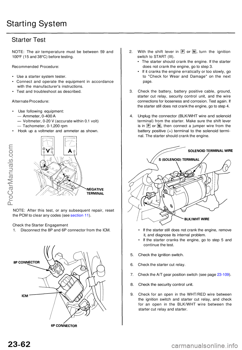
Starter Tes t
NOTE : Th e ai r temperatur e mus t b e betwee n 5 9 an d
100° F (1 5 an d 38°C ) befor e testing .
Recommende d Procedure :
• Us e a starte r syste m tester .
• Connec t an d operat e th e equipmen t i n accordanc e
wit h th e manufacturer' s instructions .
• Tes t an d troubleshoo t a s described .
Alternat e Procedure :
• Us e followin g equipment :
Ammeter, 0 -40 0 A
Voltmeter , 0 -2 0 V (accurat e withi n 0. 1 volt )
Tachometer , 0 -1,20 0 rp m
• Hoo k u p a voltmete r an d ammete r a s shown .
NOTE : Afte r thi s test , o r an y subsequen t repair , rese t
th e PC M to clea r an y code s (se e sectio n 11 ).
Chec k th e Starte r Engagemen t
1 . Disconnec t th e 8 P an d 6 P connecto r fro m th e ICM .
2. Wit h th e shif t leve r i n tur n th e ignitio n
switch t o STAR T (III) .
• Th e starte r shoul d cran k th e engine . I f th e starte r
doe s no t cran k th e engine , g o to ste p 3 .
• I f i t crank s th e engin e erraticall y o r to o slowly , g o
t o "Chec k fo r Wea r an d Damage " o n th e nex t
page .
3. Chec k th e battery , batter y positiv e cable , ground ,
starte r cu t relay , securit y contro l unit , an d th e wir e
connection s fo r loosenes s an d corrosion . Tes t again . I f
th e starte r stil l doe s no t cran k th e engine , g o to ste p 4 .
4. Unplu g th e connecto r (BLK/WH T wir e an d solenoi d
terminal ) fro m th e starter . Mak e sur e th e shif t leve r
is i n the n connec t a jumpe r wir e fro m th e
batter y positiv e (+ ) termina l t o th e solenoi d termi -
nal. Th e starte r shoul d cran k th e engine .
• I f th e starte r stil l doe s no t cran k th e engine , remov e
it , an d diagnos e it s interna l problem .
• I f th e starte r crank s th e engine , g o t o ste p 5 an d
continu e th e test .
5. Chec k th e ignitio n switch .
6. Chec k th e starte r cu t relay .
7 . Chec k th e A/ T gea r positio n switc h (se e pag e 23-109 ).
8 . Chec k th e securit y contro l unit .
9. Chec k fo r a n ope n i n th e WHT/RE D wir e betwee n
th e ignitio n switc h an d starte r cu t relay , an d chec k
fo r a n ope n i n th e BLK/WH T wir e betwee n th e
starte r cu t rela y an d starter .
ProCarManuals.com
Page 618 of 1771
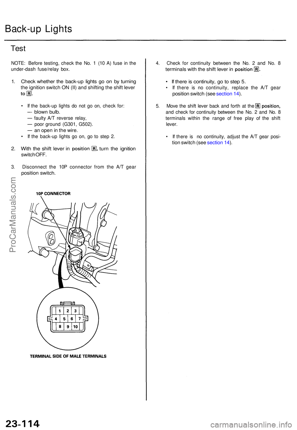
Back-up Light s
Test
NOTE : Befor e testing , chec k th e No . 1 (1 0 A ) fus e i n th e
under-das h fuse/rela y box .
1. Chec k whethe r th e back-u p light s g o o n b y turnin g
the ignitio n switc h O N (II ) an d shiftin g th e shif t leve r
• I f th e back-u p light s d o no t g o on , chec k for :
blow n bulb .
faulty A/ T revers e relay ,
poo r groun d (G301 , G502) .
an ope n in th e wire .
• I f th e back-u p light s g o on , g o t o ste p 2 .
2. Wit h th e shif t leve r i n tur n th e ignitio n
switch OFF .
3. Disconnec t th e 10 P connecto r fro m th e A/ T gea r
positio n switch .
4. Chec k fo r continuit y betwee n th e No . 2 an d No . 8
terminal s wit h th e shif t leve r i n
• I f ther e is continuity , g o to ste p 5.
• I f ther e i s n o continuity , replac e th e A/ T gea r
positio n switc h (se e sectio n 14 ).
5 . Mov e th e shif t leve r bac k an d fort h a t th e
an d chec k fo r continuit y betwee n th e No . 2 an d No . 8
terminal s withi n th e rang e o f fre e pla y o f th e shif t
lever .
• I f ther e i s n o continuity , adjus t th e A/ T gea r posi -
tion switc h (se e sectio n 14 ).
ProCarManuals.com
Page 631 of 1771
Wiper/Washer
Component Locatio n Inde x
SRS component s ar e locate d in thi s area . Revie w th e SR S componen t locations , precautions , an d procedure s i n th e SR S
sectio n (24 ) befor e performin g repair s o r service .
WINDSHIEL DWIPER/WASHE RSWITCH
Replacement , pag e 23-13 6
WINDSHIEL D WIPE R
ARMS/BLADE S
INTERMITTENT WIPE RRELAY
INTEGRATE D CONTRO L UNI T(Has built-i n intermitten t wipe r circuit )
WINDSHIEL D
WASHE R MOTO R
Replacement , sectio n 2 0 WINDSHIEL
D WIPE R MOTO R
WINDSHIEL
D WIPE R RELA Y
Test , pag e 23-5 8 Test
, pag e 23- 258
Replacement ,
sectio n 2 0
Test , pag e 23- 63
Input Test, pag e 23- 150Replacement
, section 20
Test
, pag e 23-2 60
ProCarManuals.com
Page 634 of 1771
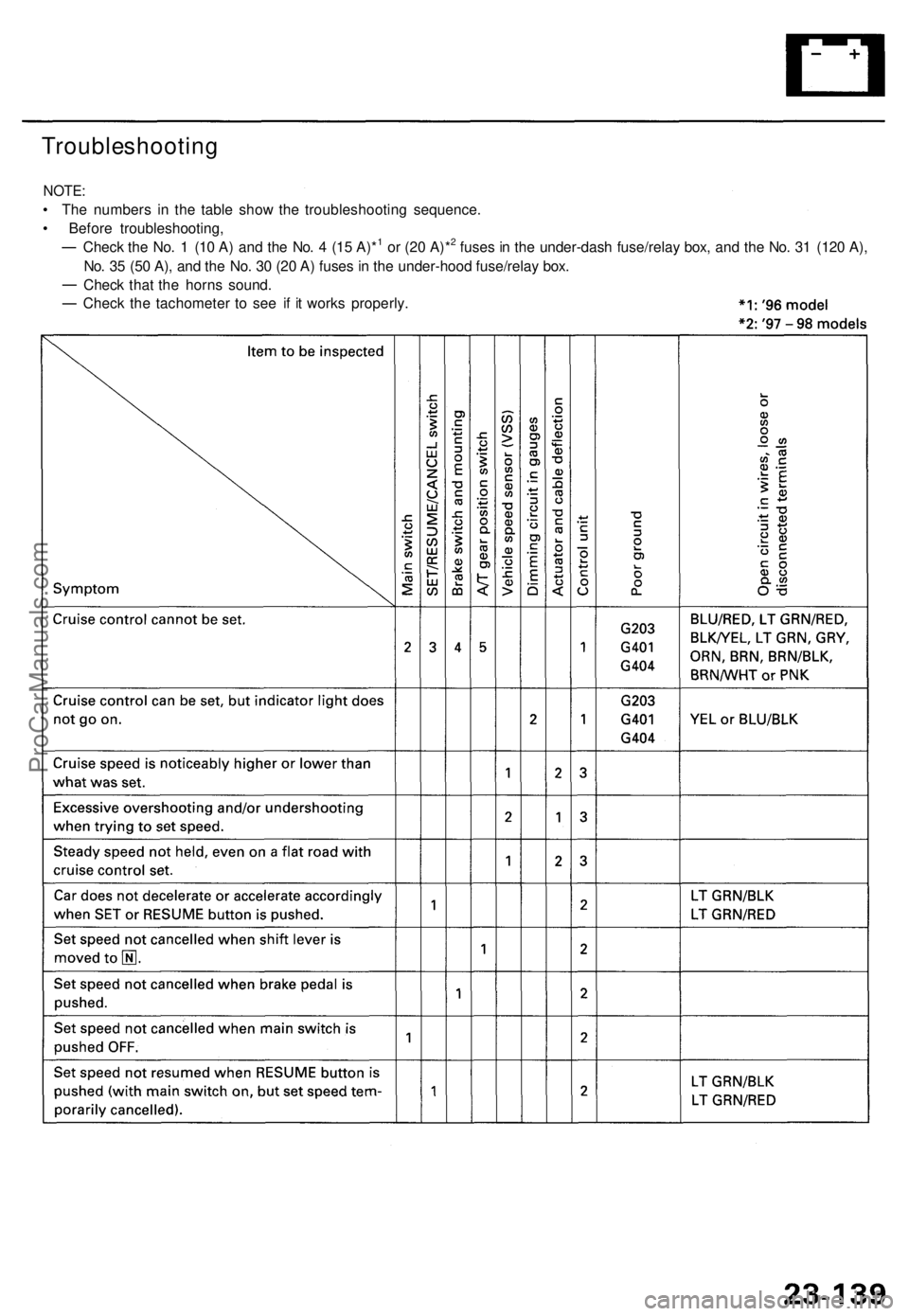
Troubleshooting
NOTE:
• The numbers in the table show the troubleshooting sequence.
• Before troubleshooting,
Check the No. 1 (10 A) and the No. 4 (15 A)*1 or (20 A)*2 fuses in the under-dash fuse/relay box, and the No. 31 (120 A),
No. 35 (50 A), and the No. 30 (20 A) fuses in the under-hood fuse/relay box.
Check that the horns sound.
Check the tachometer to see if it works properly.ProCarManuals.com
Page 640 of 1771
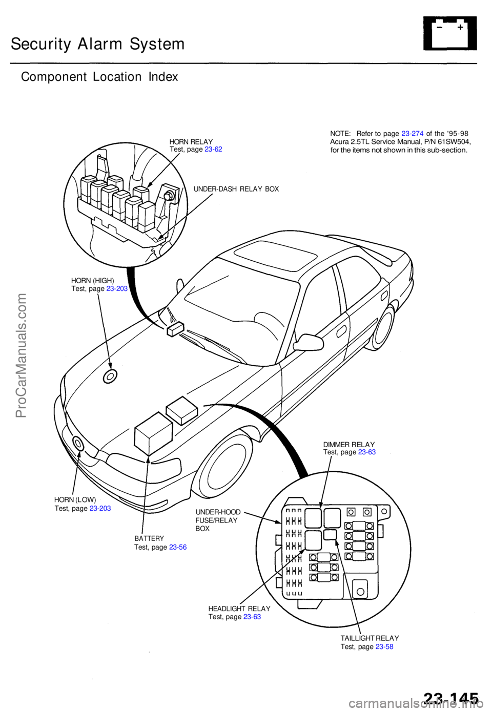
Security Alar m Syste m
Componen t Locatio n Inde x
HORN (LOW ) HOR
N RELA Y NOTE
: Refe r t o page 23-274 of the '95-9 8
Acura 2.5TL Servic e Manual , P/ N 61SW504 ,for the items no t show n in thi s sub-section .
BATTERYTest, pag e 23-5 6
HEADLIGH T RELA Y
TAILLIGH T RELA Y
Test , pag e 23-5 8
UNDER-HOO
D
FUSE/RELAYBOX
DIMME R RELA Y
UNDER-DAS H RELA Y BO X
HOR N (HIGH )
Test , pag e 23-203
Test, pag e 23- 63 Test
, pag e 23-63
Test
, pag e 23-203 Test
, pag e 23- 62
ProCarManuals.com
Page 647 of 1771
Precautions/Procedures
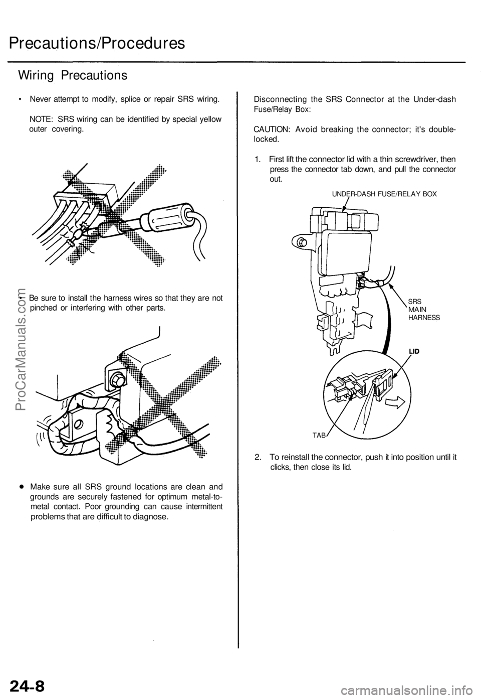
Wiring Precaution s
• Neve r attemp t t o modify , splic e o r repai r SR S wiring .
NOTE : SR S wirin g ca n b e identifie d b y specia l yello w
oute r covering .
• B e sur e to instal l th e harnes s wire s s o tha t the y ar e no t
pinche d o r interferin g wit h othe r parts .
Mak e sur e al l SR S groun d location s ar e clea n an d
ground s ar e securel y fastene d fo r optimu m metal-to -
meta l contact . Poo r groundin g ca n caus e intermitten t
problems tha t ar e difficul t t o diagnose .
Disconnectin g th e SR S Connecto r a t th e Under-das h
Fuse/Relay Box :
CAUTION : Avoi d breakin g th e connector ; it' s double -
locked.
1. Firs t lif t th e connecto r li d wit h a thi n screwdriver , the n
pres s th e connecto r ta b down , an d pul l th e connecto r
out.
UNDER-DAS H FUSE/RELA Y BO X
SRSMAI NHARNES S
TAB
2. T o reinstal l th e connector , pus h it int o positio n unti l i t
clicks , the n clos e it s lid .
ProCarManuals.com