1995 ACURA TL relay
[x] Cancel search: relayPage 931 of 1771
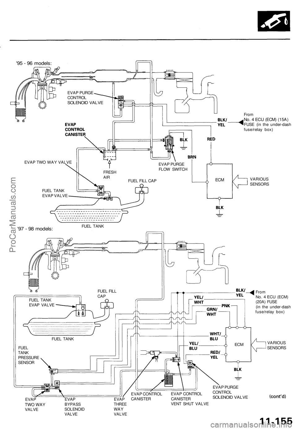
'95 - 96 models:
VARIOUS
SENSORS
From
No. 4 ECU
(ECM)
(20A) FUSE
(in the under-dash
fuse/relay box)
VARIOUS
SENSORS
EVAP
TWO WAY
VALVE
EVAP
BYPASS
SOLENOID
VALVE
EVAP
THREE
WAY
VALVE
EVAP CONTROL
CANISTER
VENT SHUT VALVE
EVAP PURGE
CONTROL
SOLENOID VALVE
ECM
ECM
From
No. 4 ECU
(ECM) (15A)
FUSE (in the under-dash
fuse/relay box)
EVAP CONTROL
CANISTER
FUEL
TANK
PRESSURE
SENSOR
FUEL TANK
FUEL FILL
CAP
FUEL TANK
EVAP VALVE
FUEL TANK
'97 - 98 models:
FUEL TANK
EVAP VALVE
EVAP TWO WAY VALVE
FRESH
AIR
FUEL FILL CAP
EVAP PURGE
FLOW SWITCH
EVAP PURGE
CONTROL
SOLENOID VALVEProCarManuals.com
Page 975 of 1771

Troubleshooting Procedures
Checking the Diagnostic Trouble Code (DTC)
with an OBD II Scan tool or Honda PGM Tester
When the TCM senses an abnormality in the input or output systems, the indicator light in the gauge assembly will
blink. When the 16P Data Link Connector (DLC) (located behind the ashtray) is connected to the OBD II Scan Tool or Honda
PGM Tester as shown, the scan tool or tester will indicate the Diagnostic Trouble Code (DTC) when the ignition switch is
turned ON(II).
When the indicator light has been reported on, connect the OBD II Scan Tool conforming to SAE J1978 or Honda PGM
Tester to the DLC (16P) behind the ashtray. Turn the ignition switch on (II), and observe the DTC on the screen of the OBD II
Scan Tool or Honda PGM Tester. After determining the DTC, refer to the electrical system Symptom-to-Component Chart
on page 14-56 and 14-57.
NOTE: See the OBD II Scan Tool or Honda PGM Tester user's manual for specific instruction.
OBD II SCAN TOOL or
HONDA PGM TESTER
Some PGM-FI problems will also make the indicator light come on. After repairing the PGM-FI system, disconnect the
BACK UP RADIO fuse (10 A) in the under-hood fuse/relay box for more than 10 seconds to reset the TCM memory, then
retest.
NOTE: Disconnecting the BACK UP RADIO fuse also cancels the radio anti-theft code, preset stations and the clock setting.
Get the customer's code number, and make note of the radio presets before removing the fuse so you can reset them.
DATA LINK CONNECTOR (16P)ProCarManuals.com
Page 978 of 1771

4. Inspec t th e circui t o n th e TC M accordin g t o th e trou -
bleshootin g flowchar t wit h th e specia l tool s an d a
digita l multimete r a s shown .
How to us e th e Backprob e Se t
Connec t th e backprob e adapter s t o th e stackin g patc h
cords , an d connec t th e cord s t o a multimeter . Usin g
th e wir e insulatio n a s a guid e fo r th e contoure d ti p o f
the backprob e adapter , gentl y slid e th e ti p int o th e
connecto r fro m th e wir e sid e unti l i t come s i n contac t
with th e termina l en d o f th e wire .
BACKPROB E SE T07SAZ-001000 A
(tw o required )
BACKPROB EADAPTER
STACKIN GPATCH COR D
TCM
DIGITA L MULTIMETE R
(Commerciall y available )
KS-AHM-32-003 ,or equivalen t
TCM Rese t Procedur e
1 . Mak e sur e yo u hav e th e anti-thef t cod e fo r th e radio ,
the n writ e dow n th e frequencie s fo r th e radio' s pre -
set buttons .
2. Tur n th e ignitio n switc h OFF .
3 . Remov e th e No . 3 9 BAC K U P RADI O fus e (1 0 A )
fro m th e under-hoo d fuse/rela y bo x fo r 1 0 second s
t o rese t th e TCM .
NOTE : Th e TC M memor y canno t b e cleare d b y
usin g th e OB D II Sca n Too l o r Hond a PG M Tester ; b e
sur e to remov e th e BAC K U P RADI O fus e to rese t th e
TCM .
BACK U P RADI O
(1 0 A ) FUS E
UNDER-HOO D
FUSE/RELAYBOX
Fina l Procedur e
NOTE : Thi s procedur e mus t b e don e afte r an y trouble -
shooting.
1. Tur n th e ignitio n switc h OFF .
2 . Disconnec t th e OB D II Sca n Too l o r Hond a PG M
Teste r fro m th e Dat a Lin k Connector , o r remov e th e
specia l too l fro m th e Servic e Chec k Connector .
3. Rese t th e TCM .
4. Tur n th e ignitio n switc h O N (II) .
5 . Ente r th e anti-thef t cod e fo r th e radio , the n ente r th e
customer' s radi o statio n presets .
ProCarManuals.com
Page 1285 of 1771

Illustrated Inde x
The accumulato r contain s high-pressur e nitroge n gas ; d o no t puncture , expos e to flame , o r attemp t t o dis -
assembl e th e accumulato r o r i t ma y explode ; sever e persona l injur y ma y result .
MODULATO R UNI T
AB S Functio n Test , pag e 19-11 2
Modulato r Functio n Check , pag e 19-11 4
Relievin g Syste m Pressure , pag e 19-11 5
Brak e Flui d Replacement , pag e 19-11 5
Removal/Installation , pag e 19-11 7
Wir e Harnes s Replacement , pag e 19-11 9
Pum p Moto r Replacement , pag e 19-11 9
Accumulato r Replacemen t an d Disposal , pag e 19-12 0
Reservoi r Replacement , pag e 19-12 0FAIL-SAF E RELAY SInspection , pag e 19-12 2
AB S CONTRO L UNI T
Replacement , pag e 19-12 1
REAR WHEE L SENSO RInspection , pag e 19-12 2
Replacement , pag e 19-12 3
ABS MOTO R RELA YInspection , pag e 19-12 2
FRON T WHEE L SENSO RInspection , pag e 19-12 2Replacement , pag e 19-12 3
ProCarManuals.com
Page 1286 of 1771
Anti-lock Brake System (ABS)
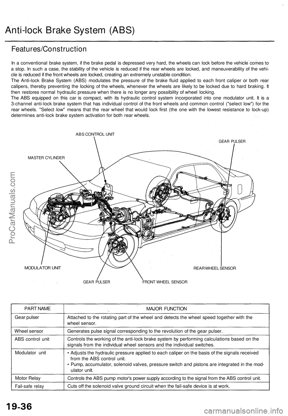
Features/Construction
In a conventional brake system, if the brake pedal is depressed very hard, the wheels can lock before the vehicle comes to
a stop. In such a case, the stability of the vehicle is reduced if the rear wheels are locked, and maneuverability of the vehi-
cle is reduced if the front wheels are locked, creating an extremely unstable condition.
The Anti-lock Brake System (ABS) modulates the pressure of the brake fluid applied to each front caliper or both rear
calipers, thereby preventing the locking of the wheels, whenever the wheels are likely to be locked due to hard braking. It
then restores normal hydraulic pressure when there is no longer any possibility of wheel locking.
The ABS equipped on this car is compact, with its hydraulic control system incorporated into one modulator unit. It is a
3-channel anti-lock brake system that has individual control of the front wheels and common control ("select low") for the
rear wheels. "Select low" means that the rear wheel that would lock first (the one with the lowest resistance to lock-up)
determines anti-lock brake system activation for both rear wheels.
ABS CONTROL UNIT
GEAR PULSER
MASTER CYLINDER
MODULATOR UNIT
REAR WHEEL SENSOR
GEAR PULSER
FRONT WHEEL SENSOR
PART NAME
Gear pulser
Wheel sensor
ABS control unit
Modulator unit
Motor Relay
Fail-safe relay
MAJOR FUNCTION
Attached to the rotating part of the wheel and detects the wheel speed together with the
wheel sensor.
Generates pulse signal corresponding to the revolution of the gear pulser.
Controls the working of the anti-lock brake system by performing calculations based on the
signals from the individual wheel sensors and the individual switches.
• Adjusts the hydraulic pressure applied to each caliper on the basis of the signals received
from the ABS control unit.
• Pump, accumulator, solenoid valves, pressure switch and pistons are integrated in the mod-
ulator unit.
Controls the ABS pump motor's power supply according to the signal from the ABS control unit.
Cuts off the solenoid valve ground circuit when the fail-safe device is at work.ProCarManuals.com
Page 1289 of 1771
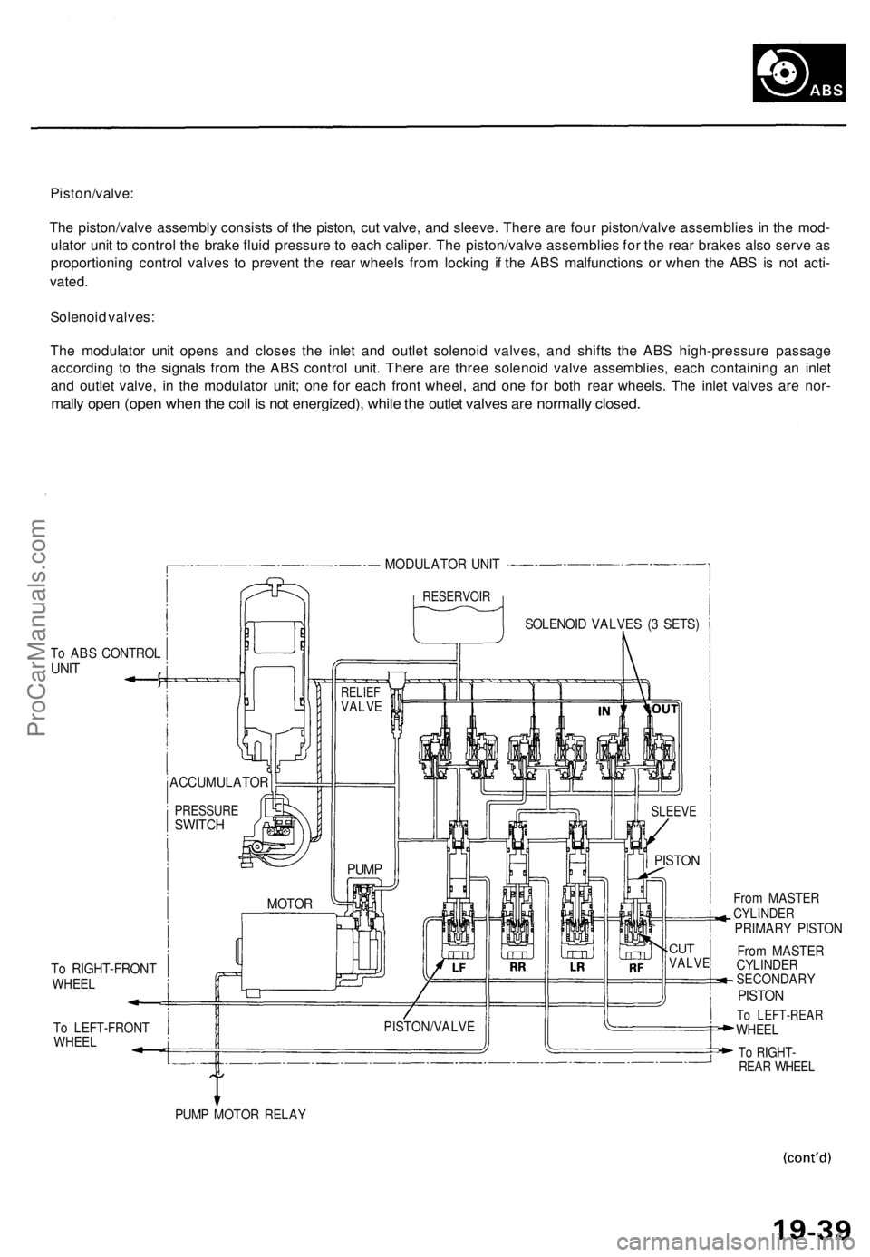
Piston/valve:
The piston/valve assembly consists of the piston, cut valve, and sleeve. There are four piston/valve assemblies in the mod-
ulator unit to control the brake fluid pressure to each caliper. The piston/valve assemblies for the rear brakes also serve as
proportioning control valves to prevent the rear wheels from locking if the ABS malfunctions or when the ABS is not acti-
vated.
Solenoid valves:
The modulator unit opens and closes the inlet and outlet solenoid valves, and shifts the ABS high-pressure passage
according to the signals from the ABS control unit. There are three solenoid valve assemblies, each containing an inlet
and outlet valve, in the modulator unit; one for each front wheel, and one for both rear wheels. The inlet valves are nor-
mally open (open when the coil is not energized), while the outlet valves are normally closed.
MODULATOR UNIT
RESERVOIR
To ABS CONTROL
UNIT
To RIGHT-FRONT
WHEEL
To LEFT-FRONT
WHEEL
PUMP MOTOR RELAY
From MASTER
CYLINDER
PRIMARY PISTON
From MASTER
CYLINDER
SECONDARY
PISTON
To LEFT-REAR
WHEEL
To RIGHT-
REAR WHEEL
MOTOR
PUMP
PISTON/VALVE
CUT
VALVE
PISTON
SLEEVE
SOLENOID VALVES (3 SETS)
RELIEF
VALVE
ACCUMULATOR
PRESSURE
SWITCHProCarManuals.com
Page 1290 of 1771
Anti-lock Brake System (ABS)
Features/Construction (cont'd)
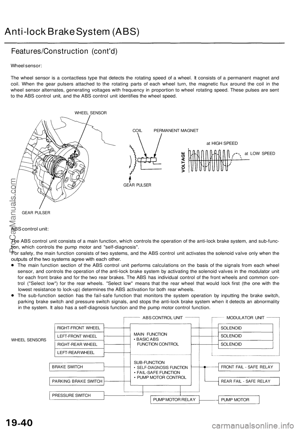
Wheel sensor:
The wheel sensor is a contactless type that detects the rotating speed of a wheel. It consists of a permanent magnet and
coil. When the gear pulsers attached to the rotating parts of each wheel turn, the magnetic flux around the coil in the
wheel sensor alternates, generating voltages with frequency in proportion to wheel rotating speed. These pulses are sent
to the ABS control unit, and the ABS control unit identifies the wheel speed.
WHEEL SENSOR
COIL PERMANENT MAGNET
at HIGH SPEED
at LOW SPEED
GEAR PULSER
GEAR PULSER
ABS control unit:
The ABS control unit consists of a main function, which controls the operation of the anti-lock brake system, and sub-func-
tion, which controls the pump motor and "self-diagnosis".
For safety, the main function consists of two systems, and the ABS control unit activates the solenoid valve only when the
outputs of the two systems agree with each other.
The main function section of the ABS control unit performs calculations on the basis of the signals from each wheel
sensor, and controls the operation of the anti-lock brake system by activating the solenoid valves in the modulator unit
for each front brake and for the two rear brakes. The ABS has individual control of the front wheels and common con-
trol ("Select low") for the rear wheels. "Select low" means that the rear wheel that would lock first (the one with the
lowest resistance to lock-up) determines the ABS activation for both rear wheels.
The sub-function section has the fail-safe function that monitors the system operation by inputting the brake switch,
parking brake switch and pressure switch signals, and stops the anti-lock brake system when it detects an abnormality
in the system. It also has a self-diagnosis function and the pump motor control function.
WHEEL SENSORS
ABS CONTROL UNIT
RIGHT-FRONT WHEEL
LEFT-FRONT WHEEL
RIGHT-REAR WHEEL
LEFT-REAR WHEEL
BRAKE SWITCH
PARKING BRAKE SWITCH
MAIN FUNCTION
• BASIC ABS
FUNCTION CONTROL
SUB-FUNCTION
• SELF-DIAGNOSIS FUNCTION
• FAIL-SAFE FUNCTION
• PUMP MOTOR CONTROL
PRESSURE SWITCH
PUMP MOTOR RELAY
MODULATOR UNIT
SOLENOID
SOLENOID
SOLENOID
FRONT FAIL - SAFE RELAY
REAR FAIL - SAFE RELAY
PUMP MOTORProCarManuals.com
Page 1291 of 1771
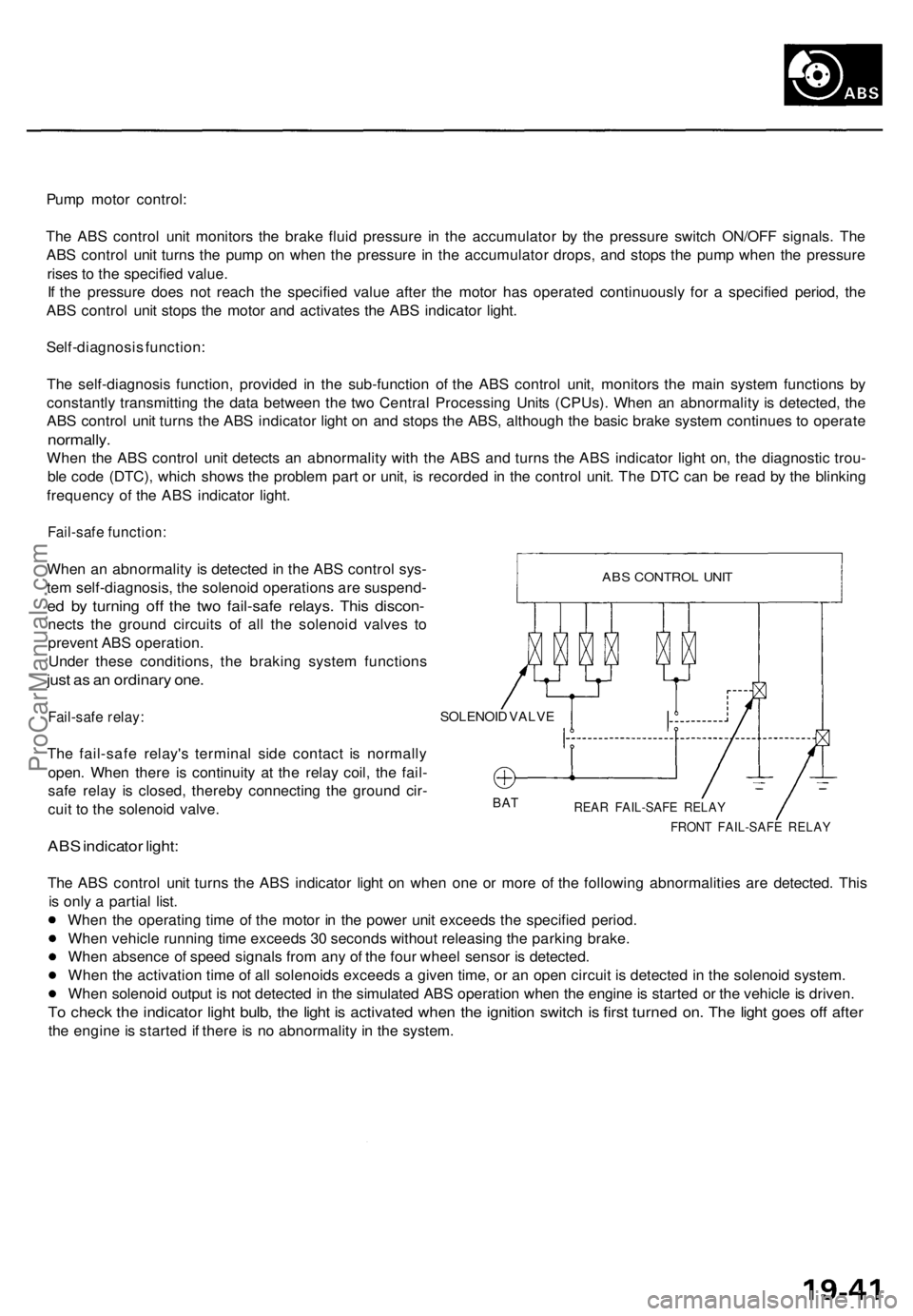
Pump motor control:
The ABS control unit monitors the brake fluid pressure in the accumulator by the pressure switch ON/OFF signals. The
ABS control unit turns the pump on when the pressure in the accumulator drops, and stops the pump when the pressure
rises to the specified value.
If the pressure does not reach the specified value after the motor has operated continuously for a specified period, the
ABS control unit stops the motor and activates the ABS indicator light.
Self-diagnosis function:
The self-diagnosis function, provided in the sub-function of the ABS control unit, monitors the main system functions by
constantly transmitting the data between the two Central Processing Units (CPUs). When an abnormality is detected, the
ABS control unit turns the ABS indicator light on and stops the ABS, although the basic brake system continues to operate
normally.
When the ABS control unit detects an abnormality with the ABS and turns the ABS indicator light on, the diagnostic trou-
ble code (DTC), which shows the problem part or unit, is recorded in the control unit. The DTC can be read by the blinking
frequency of the ABS indicator light.
Fail-safe function:
When an abnormality is detected in the ABS control sys-
tem self-diagnosis, the solenoid operations are suspend-
ed by turning off the two fail-safe relays. This discon-
nects the ground circuits of all the solenoid valves to
prevent ABS operation.
Under these conditions, the braking system functions
just as an ordinary one.
Fail-safe relay:
The fail-safe relay's terminal side contact is normally
open. When there is continuity at the relay coil, the fail-
safe relay is closed, thereby connecting the ground cir-
cuit to the solenoid valve.
ABS indicator light:
SOLENOID VALVE
BAT
REAR FAIL-SAFE RELAY
FRONT FAIL-SAFE RELAY
The ABS control unit turns the ABS indicator light on when one or more of the following abnormalities are detected. This
is only a partial list.
When the operating time of the motor in the power unit exceeds the specified period.
When vehicle running time exceeds 30 seconds without releasing the parking brake.
When absence of speed signals from any of the four wheel sensor is detected.
When the activation time of all solenoids exceeds a given time, or an open circuit is detected in the solenoid system.
When solenoid output is not detected in the simulated ABS operation when the engine is started or the vehicle is driven.
To check the indicator light bulb, the light is activated when the ignition switch is first turned on. The light goes off after
the engine is started if there is no abnormality in the system.
ABS CONTROL UNITProCarManuals.com