1995 ACURA TL steering
[x] Cancel search: steeringPage 1152 of 1771
System Description
System Operation (cont'd)
Hydraulic Control at Each Speed Range
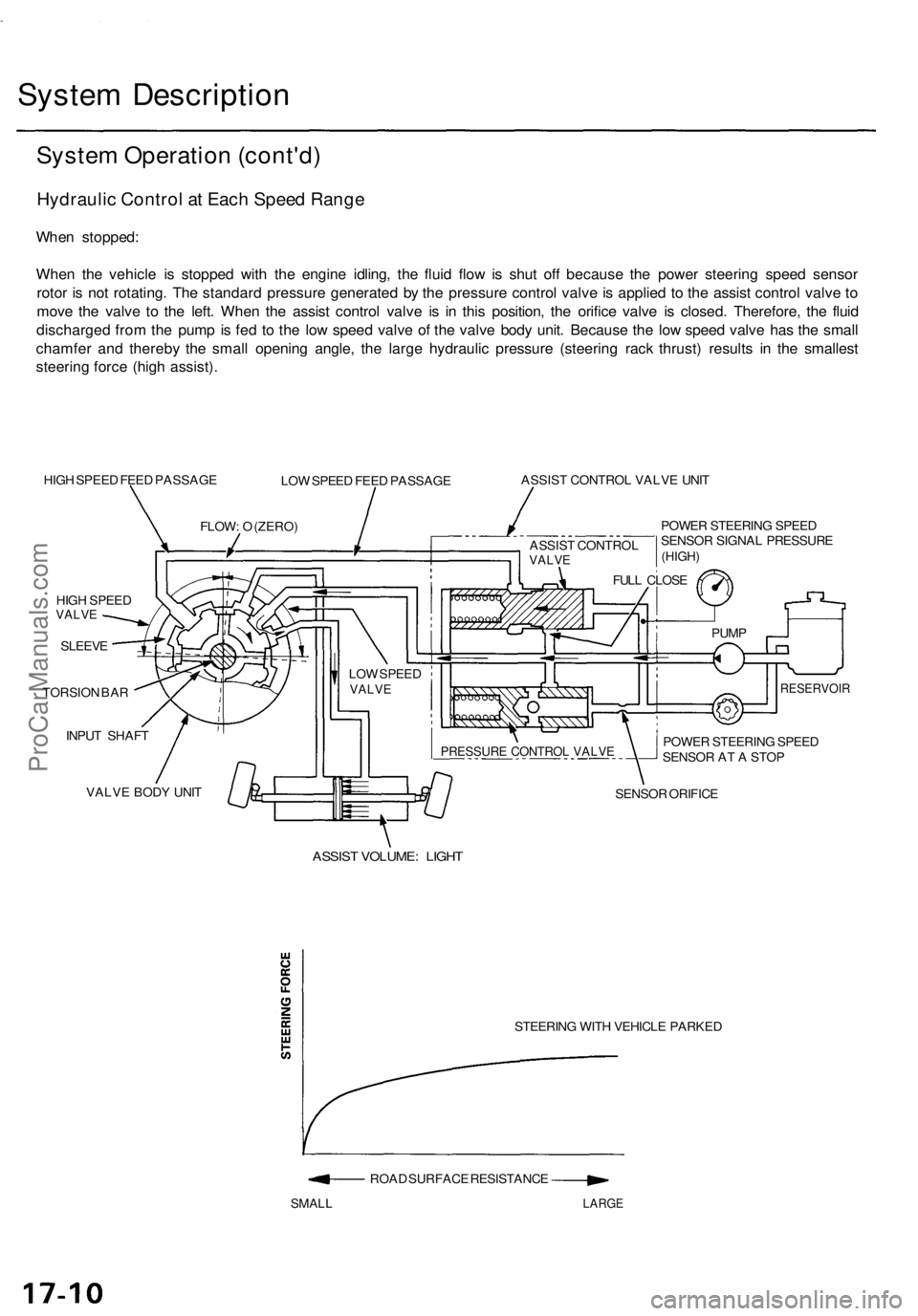
When stopped:
When the vehicle is stopped with the engine idling, the fluid flow is shut off because the power steering speed sensor
rotor is not rotating. The standard pressure generated by the pressure control valve is applied to the assist control valve to
move the valve to the left. When the assist control valve is in this position, the orifice valve is closed. Therefore, the fluid
discharged from the pump is fed to the low speed valve of the valve body unit. Because the low speed valve has the small
chamfer and thereby the small opening angle, the large hydraulic pressure (steering rack thrust) results in the smallest
steering force (high assist).
HIGH SPEED FEED PASSAGE
LOW SPEED FEED PASSAGE
ASSIST CONTROL VALVE UNIT
POWER STEERING SPEED
SENSOR SIGNAL PRESSURE
HIGH SPEED
VALVE
SLEEVE
TORSION BAR
INPUT SHAFT
VALVE BODY UNIT
SENSOR ORIFICE
ASSIST VOLUME: LIGHT
STEERING WITH VEHICLE PARKED
ROAD SURFACE RESISTANCE
SMALL
LARGE
FLOW: O (ZERO)
LOW SPEED
VALVE
POWER STEERING SPEED
SENSOR AT A STOP
RESERVOIR
PUMP
FULL CLOSE
PRESSURE CONTROL VALVE
(HIGH)
ASSIST CONTROL
VALVEProCarManuals.com
Page 1153 of 1771
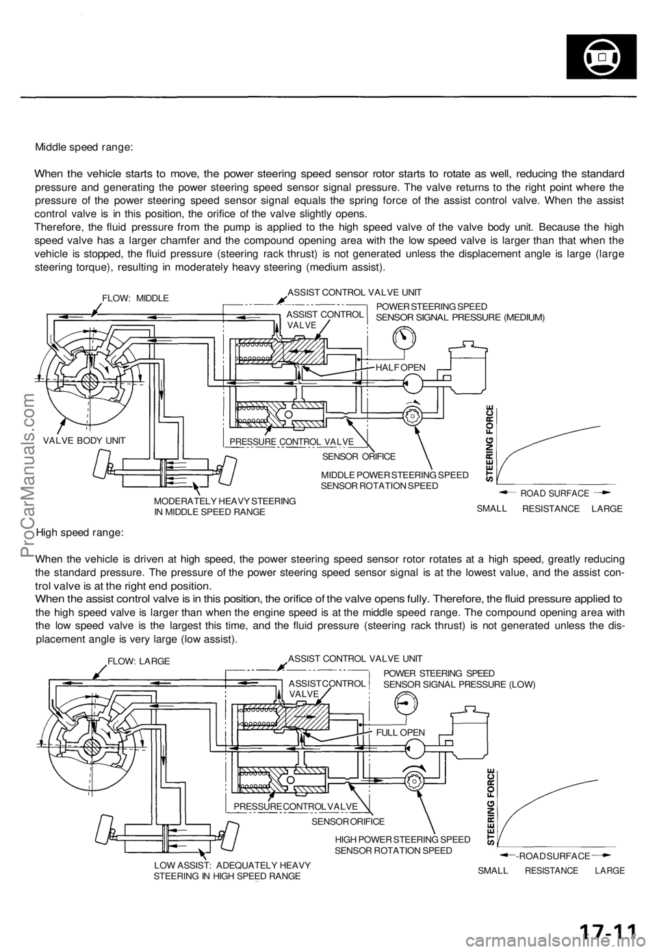
Middle speed range:
When the vehicle starts to move, the power steering speed sensor rotor starts to rotate as well, reducing the standard
pressure and generating the power steering speed sensor signal pressure. The valve returns to the right point where the
pressure of the power steering speed sensor signal equals the spring force of the assist control valve. When the assist
control valve is in this position, the orifice of the valve slightly opens.
Therefore, the fluid pressure from the pump is applied to the high speed valve of the valve body unit. Because the high
speed valve has a larger chamfer and the compound opening area with the low speed valve is larger than that when the
vehicle is stopped, the fluid pressure (steering rack thrust) is not generated unless the displacement angle is large (large
steering torque), resulting in moderately heavy steering (medium assist).
FLOW: MIDDLE
ASSIST CONTROL VALVE UNIT
POWER STEERING SPEED
SENSOR SIGNAL PRESSURE (MEDIUM)
MIDDLE POWER STEERING SPEED
SENSOR ROTATION SPEED
MODERATELY HEAVY STEERING
IN MIDDLE SPEED RANGE
SMALL
ROAD SURFACE
RESISTANCE LARGE
High speed range:
When the vehicle is driven at high speed, the power steering speed sensor rotor rotates at a high speed, greatly reducing
the standard pressure. The pressure of the power steering speed sensor signal is at the lowest value, and the assist con-
trol valve is at the right end position.
When the assist control valve is in this position, the orifice of the valve opens fully. Therefore, the fluid pressure applied to
the high speed valve is larger than when the engine speed is at the middle speed range. The compound opening area with
the low speed valve is the largest this time, and the fluid pressure (steering rack thrust) is not generated unless the dis-
placement angle is very large (low assist).
FLOW: LARGE
ASSIST CONTROL VALVE UNIT
POWER STEERING SPEED
SENSOR SIGNAL PRESSURE (LOW)
HIGH POWER STEERING SPEED
SENSOR ROTATION SPEED
LOW ASSIST: ADEQUATELY HEAVY
STEERING IN HIGH SPEED RANGE
SMALL
-ROAD SURFACE
RESISTANCE LARGE
PRESSURE CONTROL VALVE
SENSOR ORIFICE
HALF OPEN
ASSIST CONTROL
VALVE
VALVE BODY UNIT
ASSIST CONTROL
VALVE
FULL OPEN
SENSOR ORIFICE
PRESSURE CONTROL VALVEProCarManuals.com
Page 1154 of 1771
Troubleshooting
General Troubleshootin g
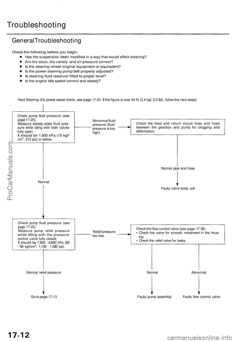
Check th e followin g befor e yo u begin :
Has th e suspensio n bee n modifie d in a wa y tha t woul d affec t steering ?
Are tir e sizes , tir e variet y an d ai r pressur e correct ?
Is th e steerin g whee l origina l equipmen t o r equivalent ?
Is th e powe r steerin g pum p bel t properl y adjusted ?
Is steerin g flui d reservoi r fille d to prope r level ?
Is th e engin e idl e spee d correc t an d steady ?
Hard Steerin g (D o powe r assis t check , se e pag e 17-20 . I f th e figur e is ove r 2 4 N (2. 4 kgf , 5. 3 Ibf) , follo w th e nex t steps )
Chec k pum p flui d pressur e (se e
pag e 17-25 ).
Measur e steady-stat e flui d pres -
sur e whil e idlin g wit h bot h valve s
fully open .It shoul d b e 1,50 0 kP a (1 5 kgf /cm2, 21 3 psi ) o r below .
Abnorma l flui dpressur e (flui d
pressur e is to o
high ) Chec
k th e fee d an d retur n circui t line s an d hos e
betwee n th e gearbo x an d pum p fo r cloggin g an d
deformation .
Norma l Norma
l pip e an d hos e
Fault y valv e bod y uni t
Chec k pum p flui d pressur e (se e
page 17-25 ).Measur e pum p relie f pressur ewhile idlin g wit h th e pressur econtrol valve full y closed .
I t shoul d b e 7,80 0 - 8,80 0 kP a (8 0
- 9 0 kgf/cm
2, 1,13 8 - 1,28 0 psi ) Relie
f pressur e
too lo w
Norma l relie f pressur e
G o to pag e 17-1 3 Norma
l
Fault y pum p assembl y Abnorma
l
Fault y flo w contro l valv e
Chec
k th e flo w contro l valv e (se e pag e 17-38 ).
• Chec k th e valv e fo r smoot h movemen t i n th e hous -
ing.• Chec k th e relie f valv e fo r leaks .
ProCarManuals.com
Page 1155 of 1771
From pag e 17-1 2
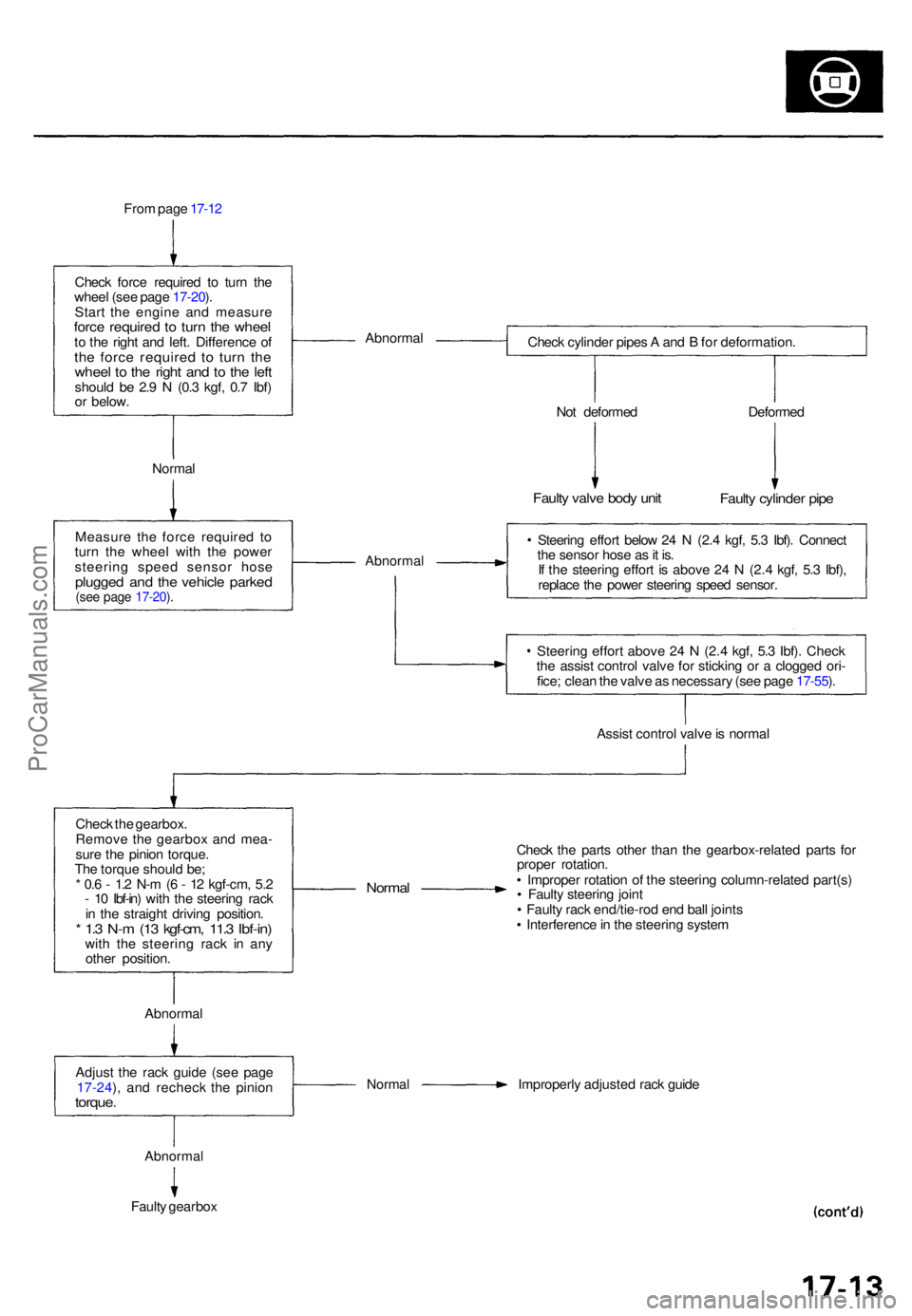
Chec k forc e require d t o tur n th e
whee l (se e pag e 17-20 ).
Star t th e engin e an d measur e
force require d t o tur n th e whee lto th e righ t an d left . Differenc e o fth e forc e require d t o tur n th ewhee l t o th e righ t an d t o th e lef tshoul d b e 2. 9 N (0. 3 kgf , 0. 7 Ibf )
o r below . Abnorma
l
Check cylinde r pipe s A an d B fo r deformation .
Norma l No
t deforme d
Faulty valv e bod y uni t
Deforme d
Faulty cylinde r pip e
Measur e th e forc e require d t o
tur n th e whee l wit h th e powe r
steerin g spee d senso r hos e
plugge d an d th e vehicl e parke d(see pag e 17-20 ).
Abnorma l
Steering effor t belo w 2 4 N (2. 4 kgf , 5. 3 Ibf) . Connec t
th e senso r hos e a s it is .
I f th e steerin g effor t i s abov e 2 4 N (2. 4 kgf , 5. 3 Ibf) ,
replac e th e powe r steerin g spee d sensor .
Steerin g effor t abov e 2 4 N (2. 4 kgf , 5. 3 Ibf) . Chec k
th e assis t contro l valv e fo r stickin g o r a clogge d ori -
fice ; clea n th e valv e a s necessar y (se e pag e 17-55 ).
Assis t contro l valv e is norma l
Chec k th e gearbox .
Remov e th e gearbo x an d mea -
sur e th e pinio n torque .
Th e torqu e shoul d be ;
* 0. 6 - 1. 2 N- m (6 - 1 2 kgf-cm , 5. 2
- 1 0 Ibf-in ) wit h th e steerin g rac k
i n th e straigh t drivin g position .
* 1. 3 N- m (1 3 kgf-cm , 11. 3 Ibf-in )with th e steerin g rac k i n an y
othe r position .
Normal
Check th e part s othe r tha n th e gearbox-relate d part s fo r
prope r rotation .
• Imprope r rotatio n o f th e steerin g column-relate d part(s )
• Fault y steerin g join t
• Fault y rac k end/tie-ro d en d bal l joint s
• Interferenc e in th e steerin g syste m
Abnorma l
Adjus t th e rac k guid e (se e pag e
17-24 ), an d rechec k th e pinio n
torque.
Norma l Improperl y adjuste d rac k guid e
Abnorma l
Faulty gearbo x
ProCarManuals.com
Page 1156 of 1771
Troubleshooting
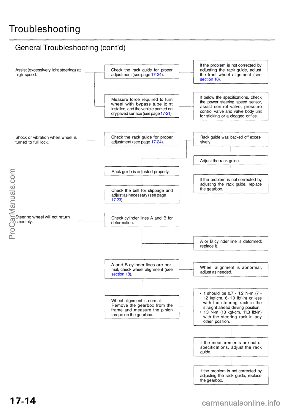
General Troubleshootin g (cont'd )
Assist (excessivel y ligh t steering ) a thig h speed . Chec
k th e rac k guid e fo r prope r
adjustmen t (se e pag e 17-24 ).
Measur e forc e require d t o tur n
whee l wit h bypas s tub e join tinstalled , an d th e vehicl e parke d o n
dr y pave d surfac e (se e pag e 17-21 ). I
f th e proble m is no t correcte d b y
adjustin g th e rac k guide , adjus tthe fron t whee l alignmen t (se e
sectio n 18 ).
I f belo w th e specifications , chec k
th e powe r steerin g spee d sensor ,
assis t contro l valve , pressur e
contro l valv e an d valv e bod y uni t
fo r stickin g o r a clogge d orifice .
Shoc k o r vibratio n whe n whee l i s
turne d t o ful l lock . Chec
k th e rac k guid e fo r prope r
adjustmen t (se e pag e 17-24 ).
Rac k guid e is adjuste d properly .
Chec k th e bel t fo r slippag e an d
adjus t a s necessar y (se e pag e
17-23 ).
Rac k guid e wa s backe d of f exces -sively.
Adjus t th e rac k guide .
I f th e proble m is no t correcte d b y
adjustin g th e rac k guide , replac e
th e gearbox .
Steering whee l wil l no t retur nsmoothly . Chec
k cylinde r line s A an d B fo r
deformation .
A an d B cylinde r line s ar e nor -mal, chec k whee l alignmen t (se e
sectio n 18 ).
Whee l alignmen t i s normal .
Remov e th e gearbo x fro m th e
fram e an d measur e th e pinio n
torqu e o n th e gearbox . A
o r B cylinde r lin e i s deformed ;
replac e it .
Whee l alignmen t i s abnormal ,
adjus t a s needed .
I t shoul d b e 0. 7 - 1. 2 N- m (7 -
1 2 kgf-cm , 6-1 0 Ibf-in ) o r les s
wit h th e steerin g rac k i n th e
straigh t ahea d drivin g position .
1. 3 N- m (1 3 kgf-cm , 11. 3 Ibf-in )
wit h th e steerin g rac k i n an y
othe r position .
I f th e measurement s ar e ou t o f
specifications , adjus t th e rac k
guide .
I f th e proble m is no t correcte d b y
adjustin g th e rac k guide , replac ethe gearbox .
ProCarManuals.com
Page 1157 of 1771
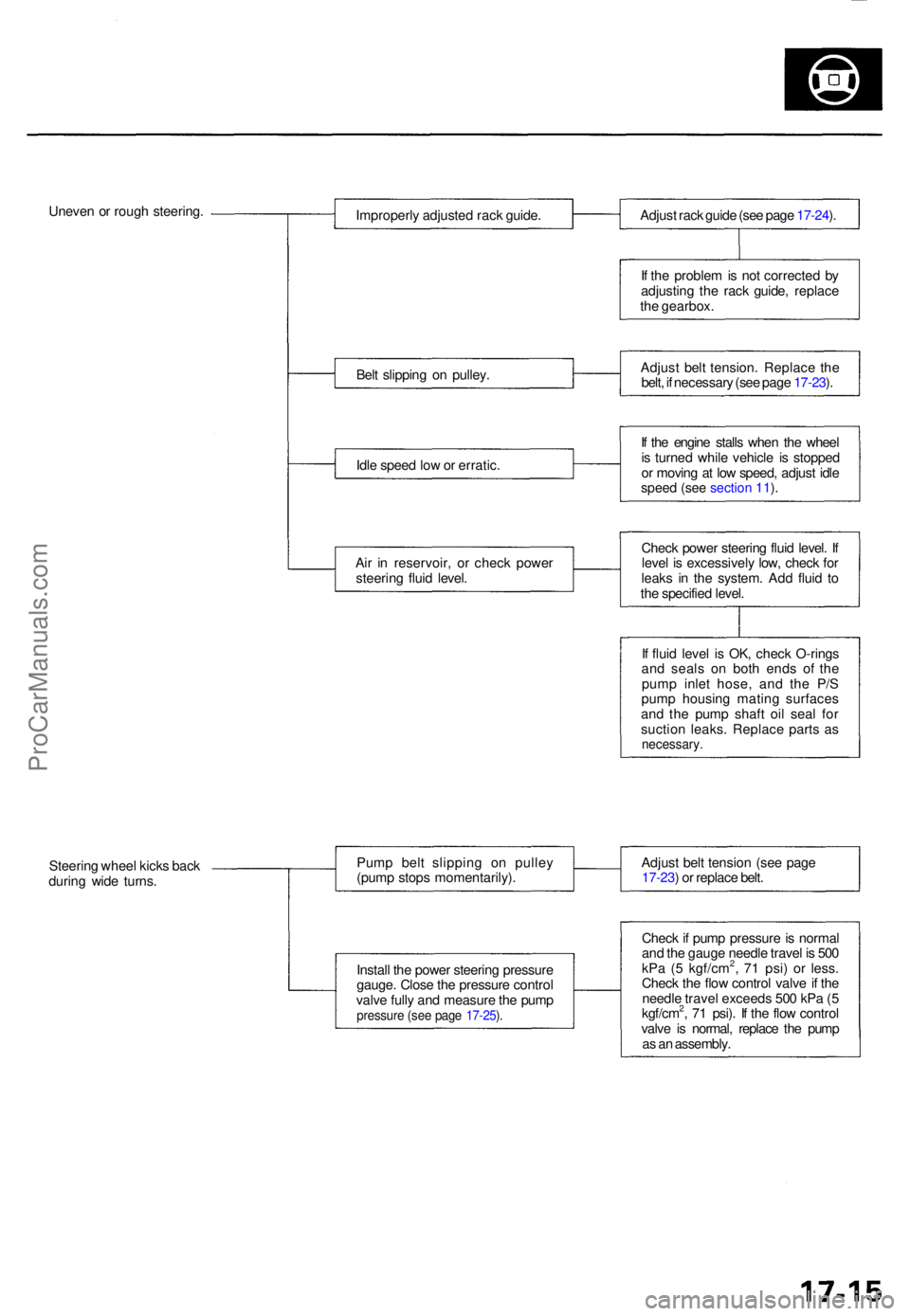
Uneven o r roug h steering .
Improperly adjuste d rac k guide .
Bel t slippin g o n pulley .
Idl e spee d lo w o r erratic .
Ai r i n reservoir , o r chec k powe r
steerin g flui d level . Adjus
t rac k guid e (se e pag e 17-24 ).
I f th e proble m is no t correcte d b y
adjustin g th e rac k guide , replac e
th e gearbox .
Adjus t bel t tension . Replac e th e
belt , i f necessar y (se e pag e 17-23 ).
I f th e engin e stall s whe n th e whee l
i s turne d whil e vehicl e i s stoppe d
o r movin g a t lo w speed , adjus t idl e
speed (see section 11).
Check powe r steerin g flui d level . I f
leve l i s excessivel y low , chec k fo r
leak s i n th e system . Ad d flui d t o
th e specifie d level .
I f flui d leve l i s OK , chec k O-ring s
an d seal s o n bot h end s o f th e
pum p inle t hose , an d th e P/ S
pum p housin g matin g surface s
an d th e pum p shaf t oi l sea l fo r
suctio n leaks . Replac e part s a s
necessary .
Steering whee l kick s bac k
durin g wid e turns . Pum
p bel t slippin g o n pulle y
(pum p stop s momentarily) .
Instal l th e powe r steerin g pressur e
gauge . Clos e th e pressur e contro l
valv e full y an d measur e th e pum p
pressur e (se e pag e 17-25 ).
Adjus t bel t tensio n (se e pag e
17-23 ) o r replac e belt .
Chec k if pum p pressur e is norma l
an d th e gaug e needl e trave l i s 50 0
kP a ( 5 kgf/cm
2, 7 1 psi ) o r less .
Chec k th e flo w contro l valv e if th e
needl e trave l exceed s 50 0 kP a ( 5
kgf/cm
2, 7 1 psi) . I f th e flo w contro l
valv e i s normal , replac e th e pum p
a s a n assembly .
ProCarManuals.com
Page 1162 of 1771
Inspection an d Adjustmen t
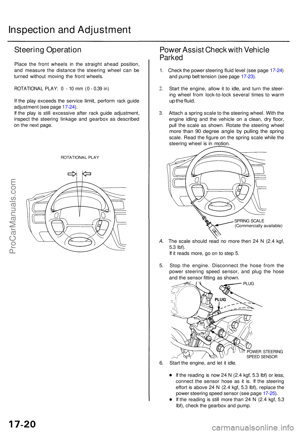
Steering Operatio n
Place th e fron t wheel s i n th e straigh t ahea d position ,
an d measur e th e distanc e th e steerin g whee l ca n b e
turne d withou t movin g th e fron t wheels .
ROTATIONA L PLAY : 0 - 10 m m (0 - 0.3 9 in )
If th e pla y exceed s the servic e limit, perfor m rack guid e
adjustmen t (se e pag e 17-24 ).
I f th e pla y i s stil l excessiv e afte r rac k guid e adjustment ,
inspec t th e steerin g linkag e an d gearbo x a s describe d
o n th e nex t page .
ROTATIONA L PLA Y
Powe r Assis t Chec k wit h Vehicl e
Parked
1. Chec k th e powe r steerin g flui d leve l (se e pag e 17-24 )
an d pum p bel t tensio n (se e pag e 17-23 ).
2 .
3 .
Star t th e engine , allo w it t o idle , an d tur n th e steer -
in g whee l fro m lock-to-loc k severa l time s t o war m
up th e fluid .
Attac h a sprin g scal e to th e steerin g wheel . Wit h th e
engin e idlin g an d th e vehicl e o n a clean , dr y floor ,
pul l th e scal e a s shown . Rotat e th e steerin g whee l
more tha n 9 0 degre e angl e b y pullin g th e sprin g
scale. Rea d th e figur e o n th e sprin g scal e whil e th e
steerin g whee l i s i n motion .
SPRING SCAL E(Commerciall y available )
A. Th e scal e shoul d rea d n o mor e the n 2 4 N (2. 4 kgf ,
5.3 Ibf) .
If i t read s more , g o o n t o ste p 5 .
5 . Sto p th e engine . Disconnec t th e hos e fro m th e
powe r steerin g spee d sensor , an d plu g th e hos e
an d th e senso r fittin g a s shown .
PLUG
POWE R STEERIN GSPEED SENSO R
6. Star t th e engine , an d le t i t idle .
I f th e readin g is no w 2 4 N (2. 4 kgf , 5. 3 Ibf ) o r less ,
connec t th e senso r hos e a s i t is . I f th e steerin g
effor t i s abov e 2 4 N (2. 4 kgf , 5. 3 Ibf) , replac e th e
powe r steerin g spee d senso r (se e pag e 17-25 ).
I f th e readin g i s stil l mor e tha n 2 4 N (2. 4 kgf , 5. 3
Ibf) , chec k th e gearbo x an d pump .
ProCarManuals.com
Page 1164 of 1771
Inspection an d Adjustmen t
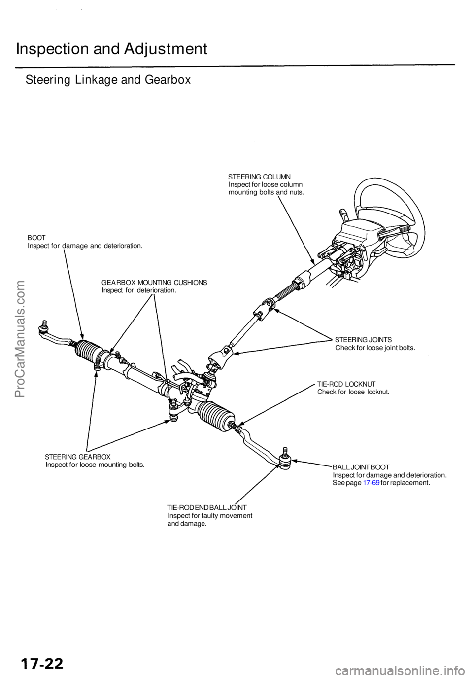
Steering Linkag e an d Gearbo x
STEERIN G COLUM NInspect fo r loos e colum n
mountin g bolt s an d nuts .
BOO TInspec t fo r damag e an d deterioration .
STEERING JOINT SCheck fo r loos e join t bolts .
TIE-RO D LOCKNU TCheck fo r loos e locknut .
STEERIN G GEARBO XInspect fo r loos e mountin g bolts .BALL JOIN T BOO T
Inspec t fo r damag e an d deterioration .
Se e pag e 17-6 9 fo r replacement .
TIE-RO D EN D BAL L JOIN T
Inspec t fo r fault y movemen t
and damage .
GEARBO X MOUNTIN G CUSHION SInspect fo r deterioration .
ProCarManuals.com