Page 1179 of 1771
Power Steering Hoses and Lines
Replacement
NOTE:
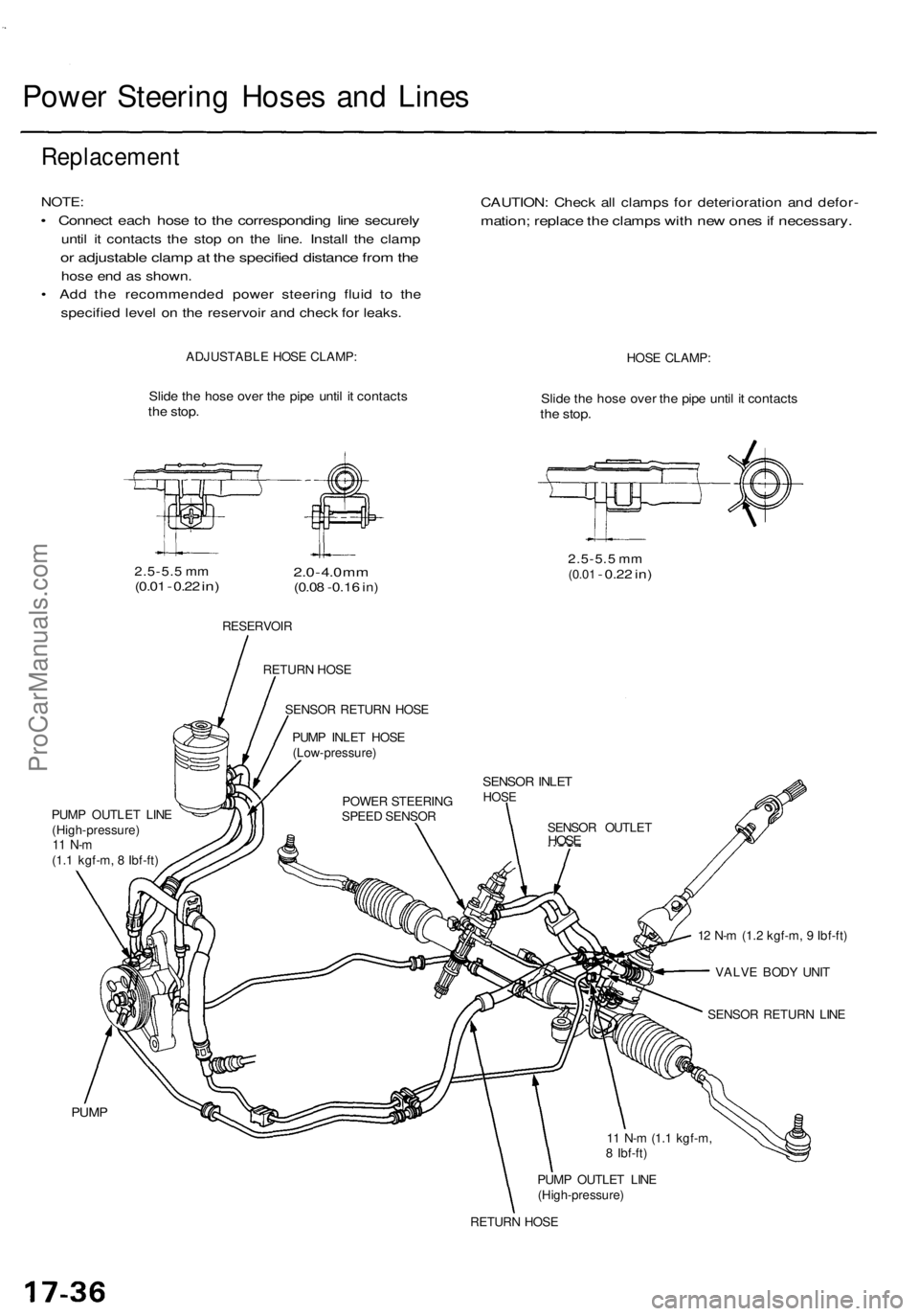
• Connect each hose to the corresponding line securely
until it contacts the stop on the line. Install the clamp
or adjustable clamp at the specified distance from the
hose end as shown.
• Add the recommended power steering fluid to the
specified level on the reservoir and check for leaks.
CAUTION: Check all clamps for deterioration and defor-
mation; replace the clamps with new ones if necessary.
ADJUSTABLE HOSE CLAMP:
HOSE CLAMP:
Slide the hose over the pipe until it contacts
the stop.
Slide the hose over the pipe until it contacts
the stop.
2.5-5.5 mm
(0.01
-
0.22
in)
2.0
-
4.0
mm
(0.08 -0.16
in)
2.5-5.5 mm
(0.01
-
0.22
in)
RESERVOIR
PUMP OUTLET LINE
(High-pressure)
11 N-m
(1.1 kgf-m, 8 Ibf-ft)
12 N-m (1.2 kgf-m, 9 Ibf-ft)
VALVE BODY UNIT
SENSOR RETURN LINE
PUMP
PUMP OUTLET LINE
(High-pressure)
RETURN HOSE
11 N-m (1.1 kgf-m,
8 Ibf-ft)
SENSOR OUTLET
HOSE
SENSOR INLET
HOSE
POWER STEERING
SPEED SENSOR
PUMP INLET HOSE
(Low-pressure)
SENSOR RETURN HOSE
RETURN HOSEProCarManuals.com
Page 1191 of 1771
Steering Gearbo x
Remova l
NOTE: Us e solven t an d a brus h t o was h of f an y oi l an d
dirt fro m th e valv e bod y unit , it s lines , an d th e en d o f
the gearbox . Blo w dr y wit h compresse d air .
1. Drai n th e powe r steerin g flui d a s describe d o n pag e
17-24 .
2. Rais e th e fron t o f vehicle , an d suppor t i t o n safet y
stands in th e prope r locations , (se e sectio n 1 )
3 . Remov e th e fron t wheels .
4 . Remov e th e driver' s airba g assembl y an d steerin g
whee l (se e pag e 17-27 ).
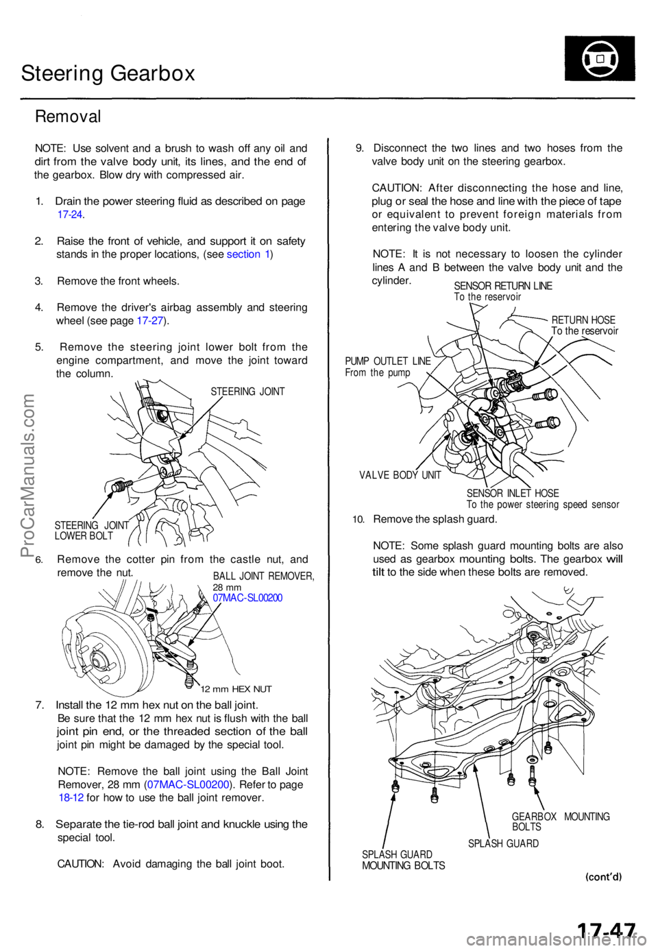
5 . Remov e th e steerin g join t lowe r bol t fro m th e
engin e compartment , an d mov e th e join t towar d
th e column .
STEERIN G JOIN T
6.
STEERIN G JOIN T
LOWE R BOL T
Remov e th e cotte r pi n fro m th e castl e nut , an d
remov e th e nut .
12 m m HE X NU T
7. Instal l th e 1 2 m m he x nu t o n th e bal l joint .
Be sur e tha t th e 1 2 m m he x nu t i s flus h wit h th e bal l
joint pi n end , o r th e threade d sectio n o f th e bal l
joint pi n migh t b e damage d b y th e specia l tool .
NOTE : Remov e th e bal l join t usin g th e Bal l Join t
Remover , 2 8 m m (07MA C-SL00200 ). Refe r t o pag e
18-12 for ho w to us e th e bal l join t remover .
8. Separat e th e tie-ro d bal l join t an d knuckl e usin g th e
specia l tool .
CAUTION : Avoi d damagin g th e bal l join t boot . 9
. Disconnec t th e tw o line s an d tw o hose s fro m th e
valv e bod y uni t o n th e steerin g gearbox .
CAUTION : Afte r disconnectin g th e hos e an d line ,
plug o r sea l th e hos e an d lin e wit h th e piec e o f tap e
or equivalen t t o preven t foreig n material s fro m
enterin g th e valv e bod y unit .
NOTE : I t i s no t necessar y t o loose n th e cylinde r
line s A an d B betwee n th e valv e bod y uni t an d th e
cylinder .
SENSOR RETUR N LIN ETo th e reservoi r
RETURN HOS E
To th e reservoi r
PUMP OUTLE T LIN E
Fro m th e pum p
VALV E BOD Y UNI T
10.
SENSO R INLE T HOS E
T o th e powe r steerin g spee d senso r
Remove th e splas h guard .
NOTE : Som e splas h guar d mountin g bolt s ar e als o
use d
as gearbo x mountin g bolts. The gearbo x will
til t
to th e sid e whe n thes e bolts are removed .
GEARBO X MOUNTIN G
BOLT S
SPLAS H GUAR D
SPLAS H GUAR D
MOUNTIN G BOLT S
BALL JOIN T REMOVER ,28 m m07MA C-SL0020 0
ProCarManuals.com
Page 1192 of 1771
Steering Gearbo x
Remova l (cont'd )
11. Unloc k th e pip e clamps , an d remov e th e senso r lin e
fro m th e rea r beam .
PIPE CLAMP S
SENSO R LIN E
SENSOR LIN E
ATTACHIN G BOL T
12. Remov e th e righ t mountin g bracke t an d steerin g
gearbox .
NOTE : Befor e removin g th e gearbox , plac e a jac k
stan d unde r th e gearbox .
CAUTION : B e carefu l no t t o ben d o r damag e th e
cylinde r line s A an d B whe n removin g th e steerin g
gearbox .
RIGHT MOUNTIN GBRACKET STEERIN
G GEARBO X
ProCarManuals.com
Page 1193 of 1771
Disassembly
Steering Rac k Disassembl y
NOTE:
• Befor e disassemblin g th e steerin g gearbox , was h i t
of f wit h solven t an d a brush .
• D o no t di p seal s an d O-ring s i n solvent .
1 . Remov e th e steerin g gearbo x (se e pag e 17-47 ).
2 . Remov e th e ai r tub e an d pip e clamps .
PIPE CLAMP S
AIR TUB E
3. Remov e th e tie-ro d en d an d locknut .
4 . Remov e th e boo t band s an d tie-ro d clips . Pul l th e
boot s awa y fro m th e end s o f th e gearbox.
BOO T BAN DReplace .
BOOTTIE RO D CLI P
5. Hol d th e steerin g rac k wit h a wrench , an d unscre w
th e rac k en d wit h another .
CAUTION : B e carefu l no t t o damag e th e rac k surfac e
wit h th e a wrench .
STEERIN G RAC K EN D
LOC K WASHE RReplace.
6. Loose n th e locknu t an d remov e th e rac k guid e
screw .
7 . Remov e th e sprin g an d rac k guid e fro m th e gearbo x
housing .
RACK GUID ESCRE W
RACK GUID E
SPRIN G
LOCKNU T
O-RINGReplace .
ProCarManuals.com
Page 1194 of 1771
Steering Gearbo x
Disassembl y (cont'd )
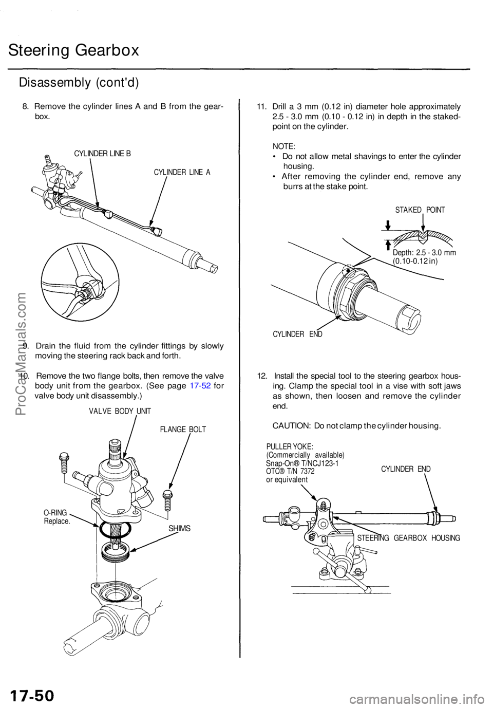
8. Remov e th e cylinde r line s A an d B fro m th e gear -
box.
CYLINDE R LIN E B
CYLINDE R LIN E A
9. Drai n th e flui d fro m th e cylinde r fitting s b y slowl y
movin g th e steerin g rac k bac k an d forth .
10 . Remov e th e tw o flang e bolts , the n remov e th e valv e
bod y uni t fro m th e gearbox . (Se e pag e 17-5 2 fo r
valv e bod y uni t disassembly. )
VALVE BOD Y UNI T
FLANG E BOL T
O-RIN G
Replace .
11. Dril l a 3 mm (0.1 2 in ) diamete r hol e approximatel y
2. 5 - 3. 0 m m (0.1 0 - 0.1 2 in ) i n dept h in th e staked -
poin t o n th e cylinder .
NOTE:
• D o no t allo w meta l shaving s t o ente r th e cylinde r
housing .
• Afte r removin g th e cylinde r end , remov e an y
burr s a t th e stak e point .
STAKE D POIN T
CYLINDE R EN D
12. Instal l th e specia l too l t o th e steerin g gearbo x hous -
ing . Clam p th e specia l too l i n a vis e wit h sof t jaw s
a s shown , the n loose n an d remov e th e cylinde r
end.
CAUTION : D o no t clam p th e cylinde r housing .
PULLER YOKE :
(Commerciall y available )
Snap-On® T/NCJ123- 1OTC® T/ N 737 2or equivalen t
CYLINDER EN D
STEERIN G GEARBO X HOUSIN G
SHIMS
Depth : 2. 5 - 3. 0 m m(0.10-0.1 2 in )
ProCarManuals.com
Page 1195 of 1771
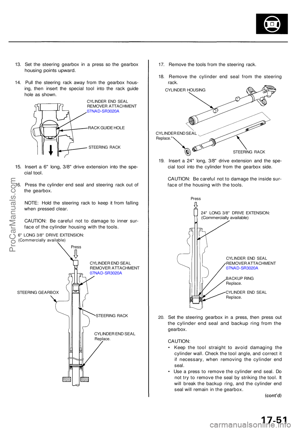
13. Se t th e steerin g gearbo x i n a pres s s o th e gearbo x
housing point s upward .
14. Pul l th e steerin g rac k awa y fro m th e gearbo x hous -
ing , the n inser t th e specia l too l int o th e rac k guid e
hol e a s shown .
CYLINDE R EN D SEA LREMOVE R ATTACHMEN T
07NA D-SR3020 A
RAC K GUID E HOL E
STEERIN G RAC K
15. Inser t a 6 " long , 3/8 " driv e extensio n int o th e spe -
cial tool .
16. Pres s th e cylinde r en d sea l an d steerin g rac k ou t o f
th e gearbox .
NOTE : Hol d th e steerin g rac k t o kee p i t fro m fallin g
whe n presse d clear .
CAUTION : B e carefu l no t t o damag e t o inne r sur -
fac e o f th e cylinde r housin g wit h th e tools .
6" LON G 3/8 " DRIV E EXTENSION :(Commerciall y available )
Press
CYLINDE R EN D SEA L
REMOVE R ATTACHMEN T
07NA D-SR3020 A
STEERIN G GEARBO X
STEERING RAC K
CYLINDE R EN D SEA LReplace .
17. Remov e th e tool s fro m th e steerin g rack .
18 . Remov e th e cylinde r en d sea l fro m th e steerin g
rack.
CYLINDE R HOUSIN G
CYLINDE R EN D SEA L
Replace. "
STEERIN G RAC K
19. Inser t a 24 " long , 3/8 " driv e extensio n an d th e spe -
cia l too l int o th e cylinde r fro m th e gearbo x side .
CAUTION : B e carefu l no t t o damag e th e insid e sur -
fac e o f th e housin g wit h th e tools .
Press
24" LON G 3/8 " DRIV E EXTENSION :(Commercially available )
20.
CYLINDE R EN D SEA LREMOVE R ATTACHMEN T
07NA D-SR3020 A
BACKU P RIN GReplace .
CYLINDE R EN D SEA LReplace .
Set th e steerin g gearbo x i n a press , the n pres s ou t
the cylinde r en d sea l an d backu p rin g fro m th e
gearbox .
CAUTION :
• Kee p th e too l straigh t t o avoi d damagin g th e
cylinde r wall . Chec k th e too l angle , an d correc t i t
i f necessary , whe n removin g th e cylinde r en d
seal .
• Us e a pres s t o remov e th e cylinde r en d seal . D o
no t tr y t o remov e th e sea l b y strikin g th e tool . I t
wil l brea k th e backu p ring , an d th e cylinde r en d
sea l wil l remai n in th e gearbox .
ProCarManuals.com
Page 1196 of 1771
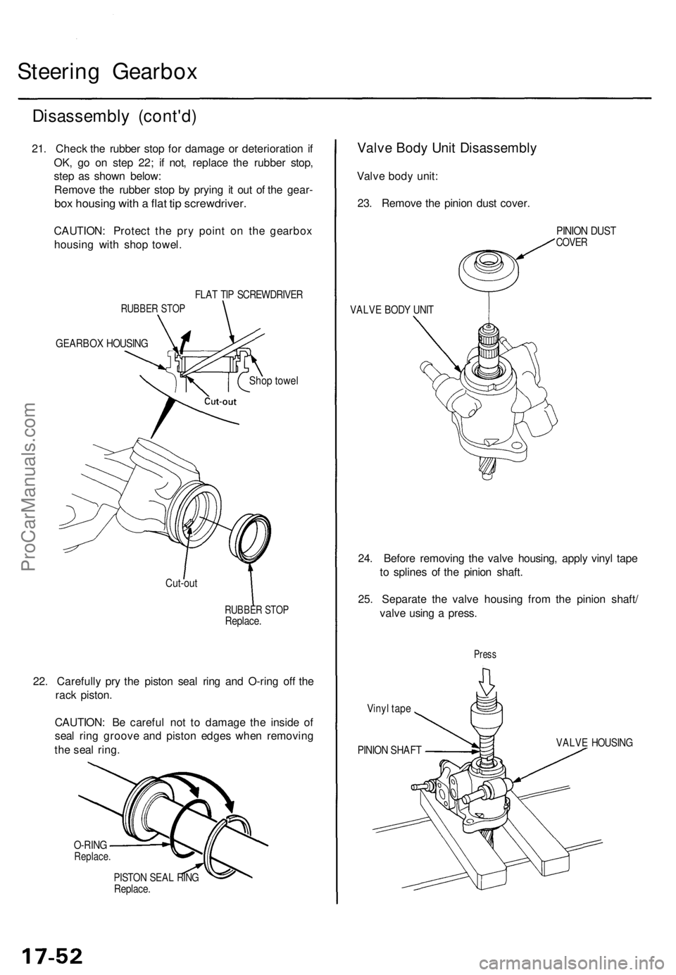
Steering Gearbo x
Disassembl y (cont'd )
21. Chec k th e rubbe r sto p fo r damag e o r deterioratio n i f
OK , g o o n ste p 22 ; i f not , replac e th e rubbe r stop ,
ste p a s show n below :
Remov e th e rubbe r sto p b y pryin g i t ou t o f th e gear -
box housin g wit h a fla t ti p screwdriver .
CAUTION: Protec t th e pr y poin t o n th e gearbo x
housin g wit h sho p towel .
FLAT TI P SCREWDRIVE R
RUBBER STO P
GEARBO X HOUSIN G
Shop towe l
Cut-ou t
RUBBE R STO PReplace .
22. Carefull y pr y th e pisto n sea l rin g an d O-rin g of f th e
rac k piston .
CAUTION : B e carefu l no t t o damag e th e insid e o f
sea l rin g groov e an d pisto n edge s whe n removin g
th e sea l ring .
O-RIN GReplace .
PISTON SEA L RIN GReplace .
Valve Bod y Uni t Disassembl y
Valve bod y unit :
23 . Remov e th e pinio n dus t cover .
VALVE BOD Y UNI T
PINIO N DUS TCOVE R
24. Befor e removin g th e valv e housing , appl y viny l tap e
t o spline s o f th e pinio n shaft .
25 . Separat e th e valv e housin g fro m th e pinio n shaft /
valv e usin g a press .
Vinyl tap e
Pres s
PINIO N SHAF TVALVE HOUSIN G
ProCarManuals.com
Page 1198 of 1771
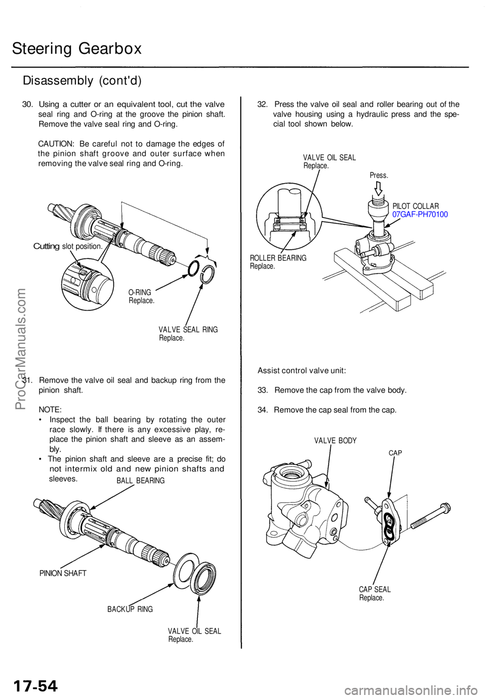
Steering Gearbo x
Disassembl y (cont'd )
30. Usin g a cutte r o r a n equivalen t tool , cu t th e valv e
seal rin g an d O-rin g a t th e groov e th e pinio n shaft .
Remov e th e valv e sea l rin g an d O-ring .
CAUTION : B e carefu l no t t o damag e th e edge s o f
th e pinio n shaf t groov e an d oute r surfac e whe n
removin g th e valv e sea l rin g an d O-ring .
Cutting slot position .
VALVE SEA L RIN G
Replace .
31. Remov e th e valv e oi l sea l an d backu p rin g fro m th e
pinio n shaft .
NOTE:
• Inspec t th e bal l bearin g b y rotatin g th e oute r
rac e slowly . I f ther e i s an y excessiv e play , re -
plac e th e pinio n shaf t an d sleev e a s a n assem -
bly.
• Th e pinio n shaf t an d sleev e ar e a precis e fit ; d o
no t intermi x ol d an d ne w pinio n shaft s an d
sleeves .
PINION SHAF T
BACKU P RIN G
VALVE OI L SEA L
Replace .
32. Pres s th e valv e oi l sea l an d rolle r bearin g ou t o f th e
valv e housin g usin g a hydrauli c pres s an d th e spe -
cia l too l show n below .
VALVE OI L SEA L
Replace .
Press.
PILO T COLLA R
07GAF-PH7010 0
ROLLER BEARIN G
Replace .
Assist contro l valv e unit :
33 . Remov e th e ca p fro m th e valv e body .
34 . Remov e th e ca p sea l fro m th e cap .
VALV E BOD Y
CAP
CAP SEA L
Replace .
O-RIN
G
Replace .
BAL L BEARIN G
ProCarManuals.com