Page 1169 of 1771
Steering Whee l
Remova l
Airbag Remova l
SRS component s ar e locate d i n thi s area . Revie w th e
SR S componen t locations , precautions , an d procedure s
i n th e SR S (sectio n 24 ) befor e performin g repair s o r ser -
vice .
1. Disconnec t th e batter y negativ e cable , the n discon -
nec t positiv e cable .
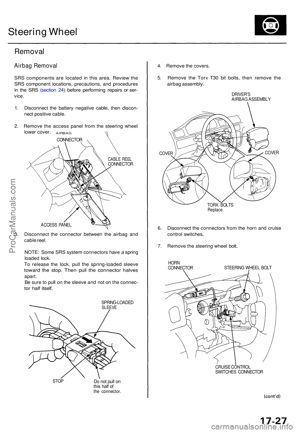
2 . Remov e th e acces s pane l fro m th e steerin g whee l
lowe r cover .
AIRBA G
CONNECTO R
CABLE REE LCONNECTO R
ACCES S PANE L
3. Disconnec t th e connecto r betwee n th e airba g an d
cabl e reel .
NOTE : Som e SR S syste m connector s hav e a sprin g
loade d lock .
T o releas e th e lock , pul l th e spring-loade d sleev e
toward th e stop . The n pul l th e connecto r halve s
apart.
Be sur e to pul l o n th e sleev e an d no t o n th e connec -
tor hal f itself .
SPRING-LOADE DSLEEVE
STOPDo no t pul l o nthi s hal f o fth e connector .
4. Remov e th e covers .
5 . Remov e th e Tor x T3 0 bi t bolts , the n remov e th e
airba g assembly .
DRIVER'S
AIRBA G ASSEMBL Y
COVERCOVE R
TORX BOLT SReplace .
6. Disconnec t th e connector s fro m th e horn and cruis e
contro l switches .
7 . Remov e th e steerin g whee l bolt .
HOR N
CONNECTO R STEERIN
G WHEE L BOL T
CRUIS E CONTRO L
SWITCHE S CONNECTO R
ProCarManuals.com
Page 1170 of 1771
Steering Whee l
Remova l (cont'd )
8. Loosel y instal l th e steerin g whee l bol t t o th e colum n
shaft , the n instal l a commercially-availabl e steerin g
whee l pulle r t o th e steerin g whee l t o remov e it .
9 . Remov e th e steerin g whee l bol t an d steerin g whee l
fro m th e colum n shaft .
CAUTION :
• D o no t ta p o n th e steerin g whee l o r th e steerin g
colum n shaf t whe n removin g th e steerin g
wheel .
• I f yo u threa d th e pulle r bolt s int o th e whee l hu b
mor e tha n fiv e threads , th e bolt s wil l hi t th e
cabl e ree l an d damag e it . T o preven t this , instal l
a pai r o f ja m nut s fiv e thread s u p o n eac h pulle r
bolt.
STEERIN G WHEE LBOLT(Instal l loosely )
STEERIN G WHEE L STEERIN
G WHEE LBOLT
17-28
STEERIN G WHEE L PULLE R
(Commerciall y available )PULLE
R BOL T
ProCarManuals.com
Page 1171 of 1771
Steering Whee l
Disassembly/Reassembl y
Store a remove d airba g assembl y with
the pa d surfac e up . I f th e airba g i s improperl y store d
face down , accidenta l deploymen t coul d prope l th e uni t
with enoug h forc e to caus e seriou s injury .
NOTE: I f a n intac t airba g assembl y ha s bee n remove d
from a scrappe d vehicle , o r ha s bee n foun d defectiv e o r
damage d durin g transit , storag e o r service , i t shoul d b e
deploye d (se e sectio n 24 ).
AIRBA G ASSEMBL Y
TORX BOL T10N-m d.Okgfm , 7 Ibf-ft)
CAUTION :
• Carefull y inspec t th e airba g assembl y befor e install -
ing. D o no t instal l a n airba g assembl y tha t show s
signs o f bein g droppe d o r improperl y handled , suc h
as dents , crack s o r deformation .
• D o no t disassembl e or tampe r with the airba g assem -
bly.
STEERIN G WHEE L
HOR N CONTAC T PLAT E
COVER
CRUIS E CONTRO L SWITCHE S
COVER
ACCESS PANE L
17-28
Steering Wheel
ProCarManuals.com
Page 1172 of 1771
Installation
Airbag installation
CAUTION:
• Before installing the steering wheel, align the front
wheels straight ahead.
• Be sure to install the harness wires so that they are
not pinched or interfering with other vehicle parts.
• Do not replace the original steering wheel with any
other design, since it will make it impossible to prop-
erly install the airbag. (Only use genuine Honda
replacement parts)
• After reassembly, confirm that the wheels are still
straight ahead and that steering wheel spoke angle
is correct. If minor spoke angle adjustment is neces-
sary, do so only by adjustment of the tie-rods, not by
removing and repositioning the steering wheel.
Confirm that the airbag assembly is
securely attached to the steering wheel; otherwise,
severe personal injury could result during airbag
deployment.
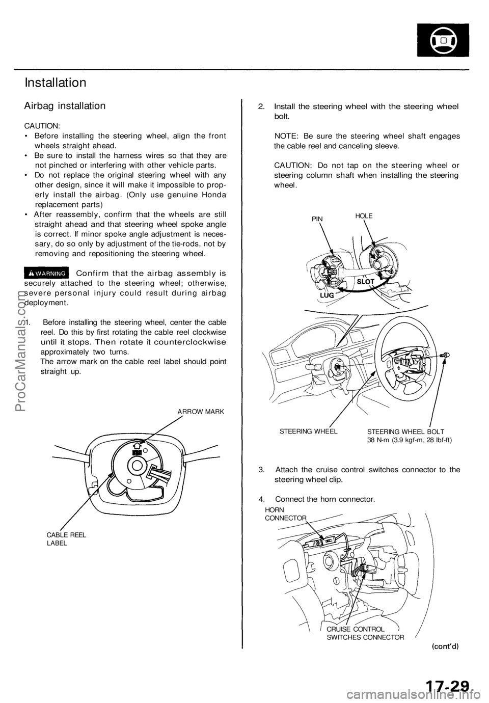
1. Before installing the steering wheel, center the cable
reel. Do this by first rotating the cable reel clockwise
until it stops. Then rotate it counterclockwise
approximately two turns.
The arrow mark on the cable reel label should point
straight up.
ARROW MARK
CABLE REEL
LABEL
2. Install the steering wheel with the steering wheel
bolt.
NOTE: Be sure the steering wheel shaft engages
the cable reel and canceling sleeve.
CAUTION: Do not tap on the steering wheel or
steering column shaft when installing the steering
wheel.
PIN
HOLE
STEERING WHEEL
STEERING WHEEL BOLT
38 N-m (3.9 kgf-m, 28 Ibf-ft)
3. Attach the cruise control switches connector to the
steering wheel clip.
4. Connect the horn connector.
HORN
CONNECTOR
CRUISE CONTROL
SWITCHES CONNECTORProCarManuals.com
Page 1173 of 1771
Steering Whee l
Installatio n (cont'd )
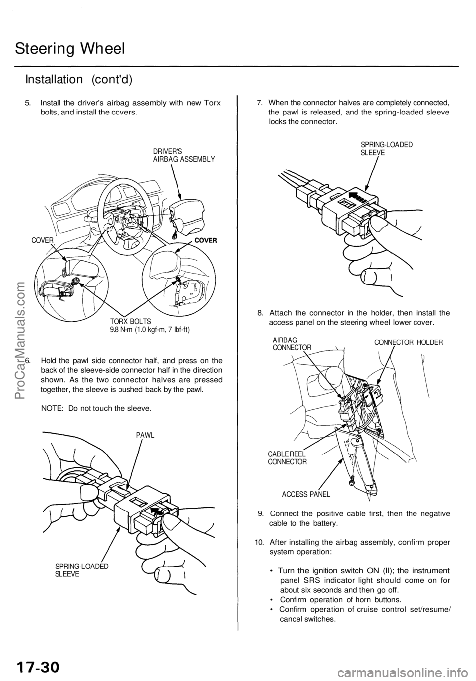
5. Instal l th e driver' s airba g assembl y wit h ne w Tor x
bolts , an d instal l th e covers .
DRIVER' S
AIRBA G ASSEMBL Y
COVER
6.
TOR X BOLT S9.8 N- m (1. 0 kgf-m , 7 Ibf-ft )
Hold th e paw l sid e connecto r half , an d pres s o n th e
bac k o f th e sleeve-sid e connecto r hal f i n th e directio n
shown . A s th e tw o connecto r halve s ar e presse d
together , th e sleev e is pushe d bac k b y th e pawl .
NOTE : D o no t touc h th e sleeve .
PAWL
SPRING-LOADE DSLEEVE
7.Whe n th e connecto r halve s ar e completel y connected ,
th e paw l i s released , an d th e spring-loade d sleev e
lock s th e connector .
SPRING-LOADE DSLEEVE
8. Attac h th e connecto r i n th e holder , the n instal l th e
acces s pane l o n th e steerin g whee l lowe r cover .
AIRBA GCONNECTO R CONNECTO
R HOLDE R
CABL E REE L
CONNECTO R
ACCES S PANE L
9. Connect the positiv e cabl e first , the n th e negativ e
cabl e t o th e battery .
10 . Afte r installin g th e airba g assembly , confir m prope r
syste m operation :
• Tur n th e ignitio n switc h O N (II) ; th e instrumen t
panel SR S indicato r ligh t shoul d com e o n fo r
abou t si x second s an d the n g o off .
• Confir m operatio n o f hor n buttons .
• Confir m operatio n o f cruis e contro l set/resume /
cance l switches .
ProCarManuals.com
Page 1174 of 1771
Steering Colum n
Remova l
SRS component s ar e locate d i n thi s area . Revie w th e
SR S componen t locations , precautions , an d procedure s
i n th e SR S (sectio n 24 ) befor e performin g repair s o r ser -
vice .
1. Remov e th e driver' s airba g assembl y an d steerin g
whee l (se e pag e 17-27 ).
2 . Remov e th e lowe r cove r an d driver' s kne e bolste r
(se e sectio n 20 ).
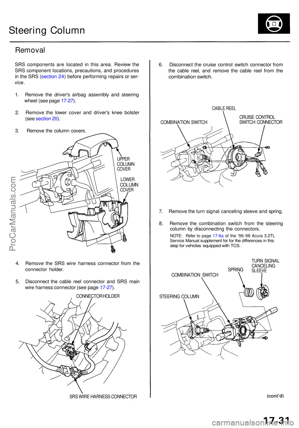
3 . Remov e th e colum n covers .
UPPERCOLUM NCOVER
LOWE R
COLUM NCOVER
4. Remov e th e SR S wir e harnes s connecto r fro m th e
connecto r holder .
5 . Disconnec t th e cabl e ree l connecto r an d SR S mai n
wir e harnes s connecto r (se e pag e 17-27 ).
CONNECTO R HOLDE R
SR S WIR E HARNES S CONNECTO R
6. Disconnec t th e cruis e contro l switc h connecto r fro m
th e cabl e reel , an d remov e th e cabl e ree l fro m th e
combinatio n switch .
CABLE REE L
COMBINATIO N SWITC H CRUIS
E CONTRO L
SWITC H CONNECTO R
7. Remov e th e tur n signa l cancelin g sleev e an d spring .
8 . Remov e th e combinatio n switc h fro m th e steerin g
colum n b y disconnectin g th e connectors .
SPRING
COMBINATIO N SWITC H
STEERIN G COLUM N TUR
N SIGNA LCANCELIN GSLEEVE
NOTE: Refe r t o page 17-6 a of th e '96-9 8 Acura 3.2TL
Servic
e Manual supplement for for the differences in this step for vehiclesequipped with TCS.
ProCarManuals.com
Page 1175 of 1771
Steering Colum n
Remova l (cont'd )
9. Remov e th e steerin g uppe r join t bol t fro m th e
engin e compartment , the n disconnec t th e steerin g
join t b y movin g th e join t towar d th e column .
UPPER JOIN T BOL T
STEERIN G JOIN T
10. Remov e th e steerin g join t cover .
STEERIN G JOIN T COVE R
CLIPSCLAMP S
11. Disconnec t th e ignitio n switc h connectors .
12 . Remov e th e steerin g colum n b y removin g th e mount -
in g nut s an d bolts .
STEERIN G COLUM N
COLUMN HOLDE R
COLUMN MOUNTIN G BOLT S IGNITIO
N SWITC H
CONNECTOR S
COLUMN MOUNTIN G NUT S
ProCarManuals.com
Page 1177 of 1771
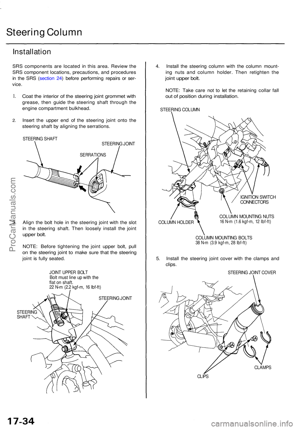
Steering Colum n
Installatio n
SRS component s ar e locate d i n thi s area . Revie w th e
SR S componen t locations , precautions , an d procedure s
i n th e SR S ( sectio n 24 ) befor e performin g repair s o r ser -
vice .
1.
2 .
Coa t th e interio r o f th e steerin g join t gromme t wit h
grease , the n guid e th e steerin g shaf t throug h th e
engin e compartmen t bulkhead .
Inser t th e uppe r en d o f th e steerin g join t ont o th e
steerin g shaf t b y alignin g th e serrations .
STEERING SHAF TSTEERIN G JOIN T
SERRATION S
3. Alig n th e bol t hol e i n th e steerin g join t wit h th e slo t
i n th e steerin g shaft . The n loosel y instal l th e join t
uppe r bolt .
NOTE : Befor e tightenin g th e join t uppe r bolt , pul l
on th e steerin g join t t o mak e sur e tha t th e steerin g
joint i s full y seated .
JOINT UPPE R BOL TBolt mus t lin e u p wit h th eflat o n shaft .22 N- m (2. 2 kgf-m , 1 6 Ibf-ft )
STEERIN G JOIN T
STEERIN GSHAFT
4. Instal l th e steerin g colum n wit h th e colum n mount -
in g nut s an d colum n holder . The n retighte n th e
join t uppe r bolt .
NOTE : Tak e car e no t t o le t th e retainin g colla r fal l
out o f positio n durin g installation .
STEERING COLUM N
COLUMN HOLDE R
IGNITION SWITC HCONNECTOR S
COLUMN MOUNTIN G NUT S16 N- m (1. 6 kgf-m , 1 2 Ibf-ft )
COLUM N MOUNTIN G BOLT S38 N- m (3. 9 kgf-m , 2 8 Ibf-ft )
5. Instal l th e steerin g join t cove r wit h th e clamp s an d
clips .
STEERIN G JOIN T COVE R
CLAMP S
CLIPS
ProCarManuals.com