1995 ACURA TL steering
[x] Cancel search: steeringPage 1200 of 1771
Steering Gearbo x
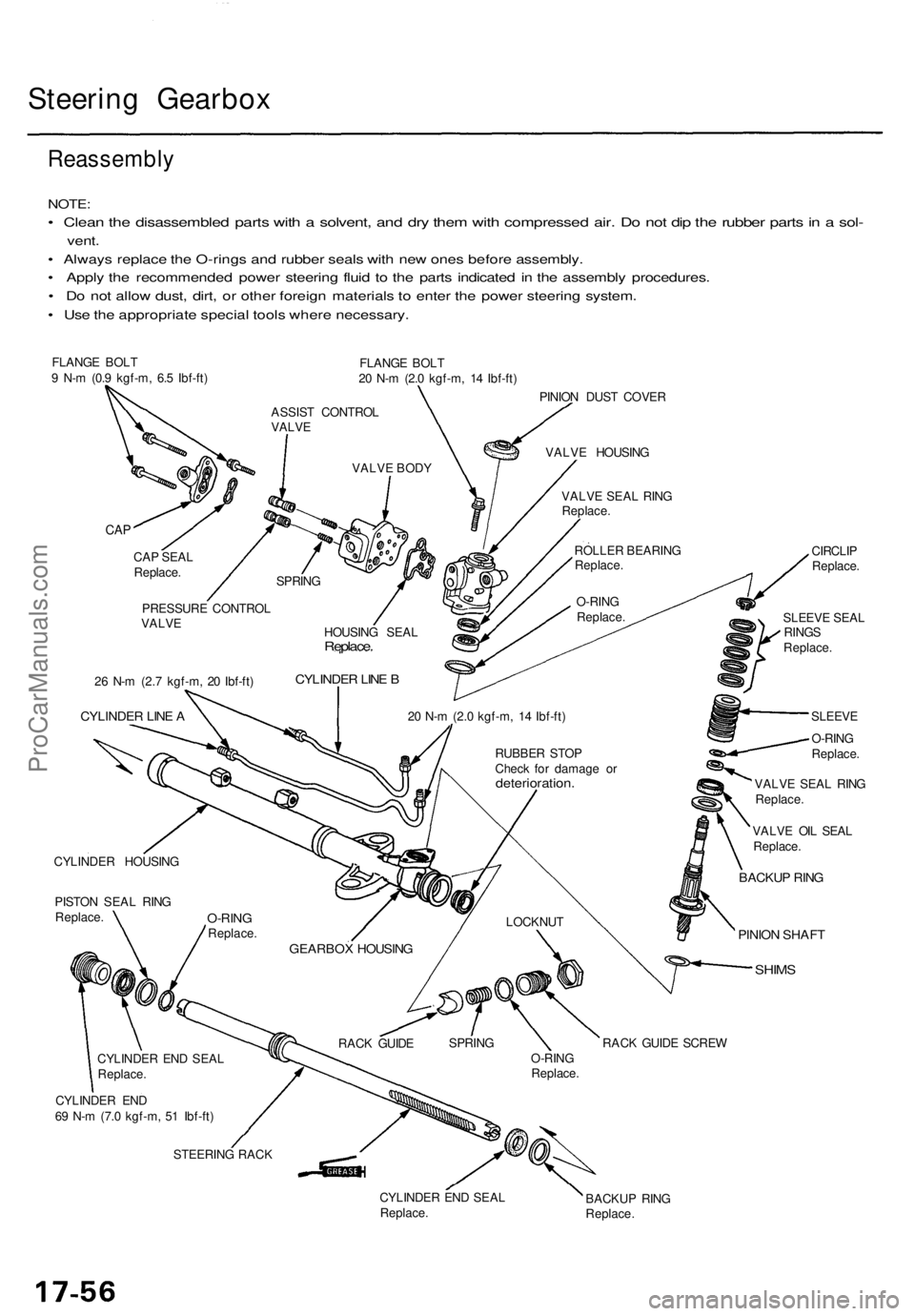
Reassembl y
NOTE:
• Clea n th e disassemble d part s wit h a solvent , an d dr y the m wit h compresse d air . D o no t di p th e rubbe r part s in a sol -
vent .
• Alway s replac e th e O-ring s an d rubbe r seal s wit h ne w one s befor e assembly .
• Appl y th e recommende d powe r steerin g flui d t o th e part s indicate d i n th e assembl y procedures .
• D o no t allo w dust , dirt , o r othe r foreig n material s t o ente r th e powe r steerin g system .
• Us e th e appropriat e specia l tool s wher e necessary .
FLANGE BOL T
9 N- m (0. 9 kgf-m , 6. 5 Ibf-ft ) FLANG
E BOL T
2 0 N- m (2. 0 kgf-m , 1 4 Ibf-ft )
PINIO N DUS T COVE R
CYLINDE R HOUSIN G
PISTO N SEA L RIN G
Replace . CIRCLI
P
Replace .
SLEEV E SEA L
RING S
Replace .
SLEEV E
O-RIN G
Replace .
VALV E SEA L RIN G
Replace .
VALV E OI L SEA L
Replace .
BACKUP RIN G
PINIO N SHAF T
SHIMS
CYLINDE R EN D
6 9 N- m (7. 0 kgf-m , 5 1 Ibf-ft )
STEERIN G RAC K
CYLINDER EN D SEA L
Replace . BACKU
P RIN G
Replace .
ASSIST CONTRO L
VALV E
VALVE BOD Y VALV
E HOUSIN G
VALV E SEA L RIN G
Replace .
ROLLE R BEARIN G
Replace .
O-RIN G
Replace .
SPRIN
G
CAP
CA P SEA L
Replace .
HOUSING SEA L
Replace .
CYLINDE R LIN E B
20 N- m (2. 0 kgf-m , 1 4 Ibf-ft )
RUBBE R STO P
Chec k fo r damag e o r
deterioration .
LOCKNUT
GEARBO X HOUSIN G
RACK GUID E SPRIN
G
O-RING
Replace .RAC
K GUID E SCRE W
PRESSUR
E CONTRO L
VALV E
2 6 N- m (2. 7 kgf-m , 2 0 Ibf-ft )
CYLINDE R LIN E A
O-RIN GReplace .
CYLINDE R EN D SEA L
Replace .
ProCarManuals.com
Page 1202 of 1771
Steering Gearbo x
Reassembl y (cont'd )
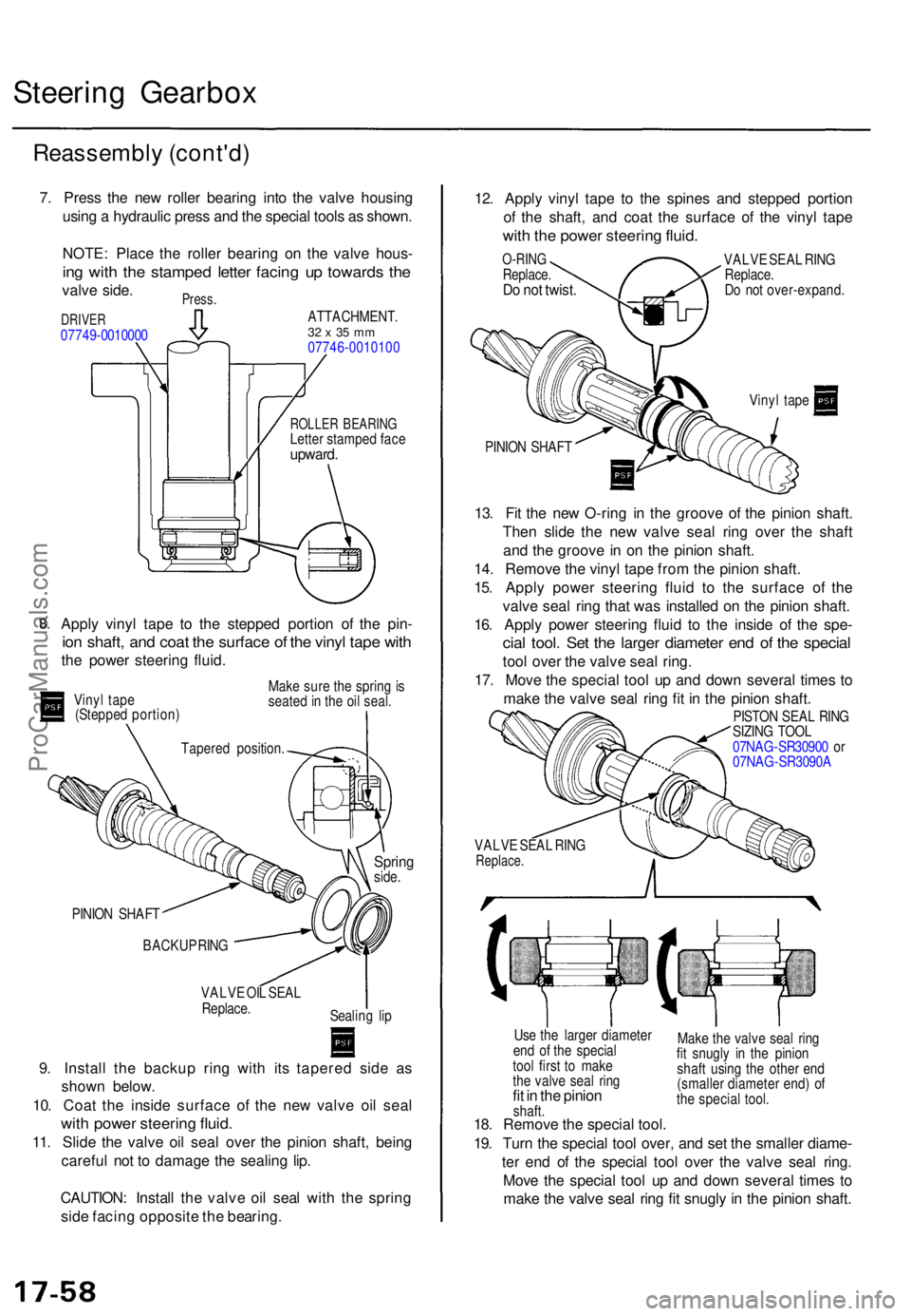
7. Pres s th e ne w rolle r bearin g int o th e valv e housin g
usin g a hydrauli c pres s an d th e specia l tool s a s shown .
NOTE : Plac e th e rolle r bearin g o n th e valv e hous -
ing wit h th e stampe d lette r facin g u p toward s th e
valv e side .Press .
DRIVE R07749-001000 0
ATTACHMENT .32 x 35 m m07746-001010 0
ROLLER BEARIN GLetter stampe d fac eupward .
8.Appl y viny l tap e t o th e steppe d portio n o f th e pin -
ion shaft , an d coa t th e surfac e o f th e viny l tap e wit h
the powe r steerin g fluid .
Vinyl tap e
(Steppe d portion ) Mak
e sur e th e sprin g i s
seate d in th e oi l seal .
Sprin gside.
PINIO N SHAF T
BACKU P RIN G
VALV E OI L SEA L
Replace .
9. Instal l th e backu p rin g wit h it s tapere d sid e a s
show n below .
10 . Coa t th e insid e surfac e of the ne w valv e oi l sea l
with powe r steerin g fluid .
11. Slid e th e valv e oi l sea l ove r th e pinio n shaft , bein g
carefu l no t t o damag e th e sealin g lip .
CAUTION : Instal l th e valv e oi l sea l wit h th e sprin g
sid e facin g opposit e th e bearing . 12
. Appl y viny l tap e t o th e spine s an d steppe d portio n
o f th e shaft , an d coa t th e surfac e o f th e viny l tap e
with th e powe r steerin g fluid .
O-RIN GReplace .Do no t twist .
VALV E SEA L RIN G
Replace .
D o no t over-expand .
Viny l tap e
PINIO N SHAF T
13. Fi t th e ne w O-rin g i n th e groov e o f th e pinio n shaft .
The n slid e th e ne w valv e sea l rin g ove r th e shaf t
an d th e groov e in o n th e pinio n shaft .
14 . Remov e th e vinyl tape fro m th e pinio n shaft .
15 . Appl y powe r steerin g flui d t o th e surfac e of the
valv e sea l rin g tha t wa s installe d o n th e pinio n shaft .
16 . Appl y powe r steerin g flui d t o th e insid e o f th e spe -
cial tool . Se t th e large r diamete r en d o f th e specia l
tool ove r th e valv e sea l ring .
17 . Mov e th e specia l too l u p an d dow n severa l time s t o
mak e th e valv e sea l rin g fi t i n th e pinio n shaft .
Make th e valv e sea l rin g
fi t snugl y i n th e pinio n
shaf t usin g th e othe r en d
(smalle r diamete r end ) o f
th e specia l tool .
Us
e th e large r diamete r
en d o f th e specia l
too l firs t t o mak e
th e valv e sea l rin g
fit i n th e pinio nshaft.18. Remov e th e specia l tool .
19 . Tur n th e specia l too l over , an d se t th e smalle r diame -
te r en d o f th e specia l too l ove r th e valv e sea l ring .
Mov e th e specia l too l u p an d dow n severa l time s t o
mak e th e valv e sea l rin g fi t snugl y in th e pinio n shaft .
Tapere d position .
Sealing li p VALV
E SEA L RIN G
Replace .
PISTON SEA L RIN G
SIZIN G TOO L
07NA G-SR3090 0 o r
07NA G-SR3090 A
ProCarManuals.com
Page 1204 of 1771
Steering Gearbo x
Reassembl y (cont'd )
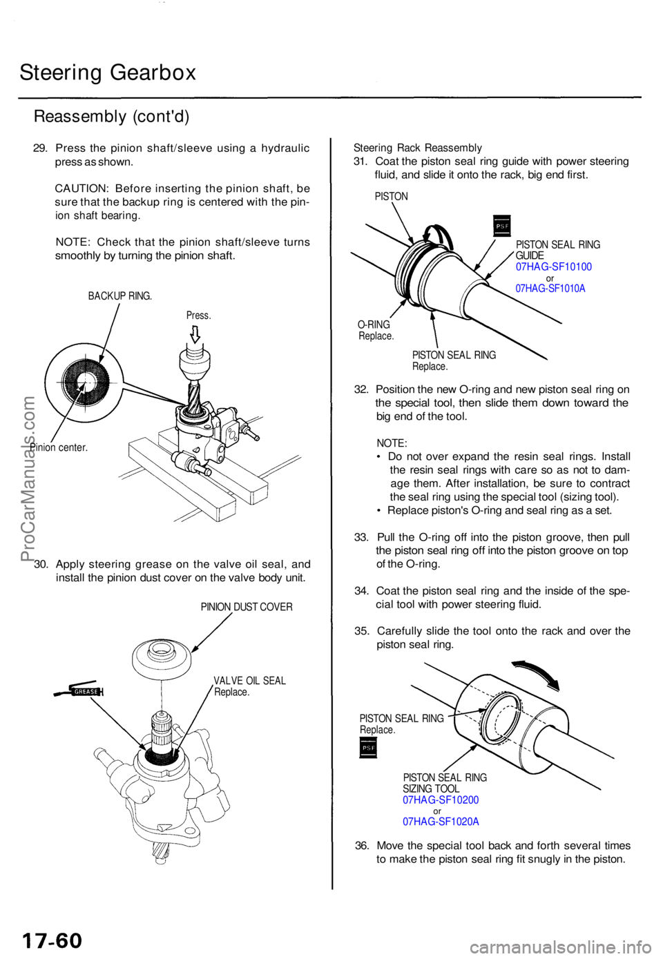
29. Pres s th e pinio n shaft/sleev e usin g a hydrauli c
pres s a s shown .
CAUTION : Befor e insertin g th e pinio n shaft , b e
sur e tha t th e backu p rin g is centere d wit h th e pin -
ion shaf t bearing .
NOTE: Chec k tha t th e pinio n shaft/sleev e turn s
smoothl y b y turnin g th e pinio n shaft .
BACKU P RING .
Press .
Pinion center .
30. Appl y steerin g greas e o n th e valv e oi l seal , an d
instal l th e pinio n dus t cove r o n th e valv e bod y unit .
PINIO N DUS T COVE R
VALVE OI L SEA LReplace .
Steering Rac k Reassembl y
31. Coa t th e pisto n sea l rin g guid e wit h powe r steerin g
fluid , an d slid e it ont o th e rack , bi g en d first .
PISTO N
PISTON SEA L RIN GGUID E07HAG-SF1010 0or07HA G-SF1010 A
O-RINGReplace .
PISTON SEA L RIN GReplace .
32. Positio n th e ne w O-rin g an d ne w pisto n sea l rin g o n
the specia l tool , the n slid e the m dow n towar d th e
big en d o f th e tool .
NOTE :
• D o no t ove r expan d th e resi n sea l rings . Instal l
th e resi n sea l ring s wit h car e s o a s no t t o dam -
ag e them . Afte r installation , b e sur e t o contrac t
th e sea l rin g usin g th e specia l too l (sizin g tool) .
• Replac e piston' s O-rin g an d sea l rin g a s a set .
33 . Pul l th e O-rin g of f int o th e pisto n groove , the n pul l
the pisto n sea l rin g of f int o th e pisto n groov e o n to p
of th e O-ring .
34 . Coa t th e pisto n sea l rin g an d th e insid e o f th e spe -
cia l too l wit h powe r steerin g fluid .
35 . Carefull y slid e th e too l ont o th e rac k an d ove r th e
pisto n sea l ring .
PISTO N SEA L RIN GReplace .
PISTON SEA L RIN GSIZIN G TOO L07HAG-SF1020 0or07HAG-SF1020 A
36. Mov e th e specia l too l bac k an d fort h severa l time s
t o mak e th e pisto n sea l rin g fi t snugl y in th e piston .
ProCarManuals.com
Page 1206 of 1771
Steering Gearbo x
Reassembl y (cont'd )
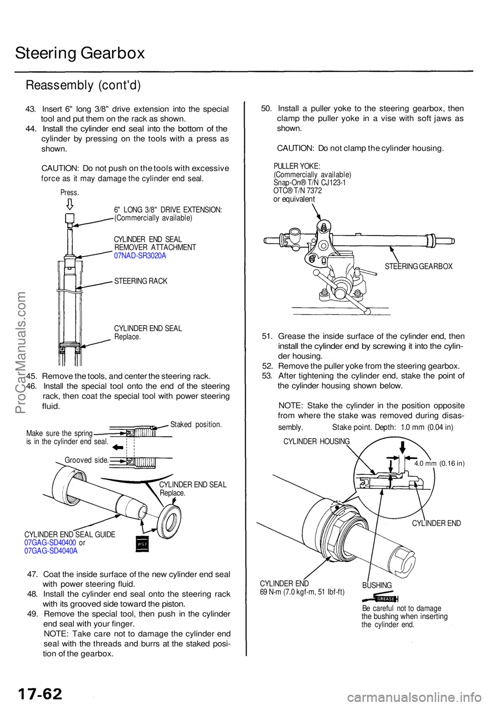
43. Inser t 6 " lon g 3/8 " driv e extensio n int o th e specia l
too l an d pu t the m on th e rac k a s shown .
44. Instal l th e cylinde r en d sea l int o th e botto m o f th e
cylinde r b y pressin g o n th e tool s wit h a pres s a s
shown .
CAUTION : D o no t pus h o n th e tool s wit h excessiv e
force a s i t ma y damag e th e cylinde r en d seal .
Press .
STEERIN G RAC K
CYLINDE R EN D SEA L
Replace .
a
45. Remov e th e tools , an d cente r th e steerin g rack .
46 . Instal l th e specia l too l ont o th e en d o f th e steerin g
rack , the n coa t th e specia l too l wit h powe r steerin g
fluid.
Stake d position .
Mak e sur e th e sprin g
i s i n th e cylinde r en d seal .
Groove d side .
CYLINDER EN D SEA L
Replace .
CYLINDE R EN D SEA L GUID E
07GA G-SD4040 0 o r
07GA G-SD4040 A
47. Coa t th e insid e surfac e o f th e ne w cylinde r en d sea l
wit h powe r steerin g fluid .
48 . Instal l th e cylinde r en d sea l ont o th e steerin g rac k
with it s groove d sid e towar d th e piston .
49. Remov e th e specia l tool , the n pus h i n th e cylinde r
en d sea l wit h you r finger.
NOTE : Tak e car e no t t o damag e th e cylinde r en d
sea l wit h th e thread s an d burr s a t th e stake d posi -
tio n o f th e gearbox . 50
. Instal l a pulle r yok e t o th e steerin g gearbox , the n
clam p th e pulle r yok e i n a vis e wit h sof t jaw s a s
shown .
CAUTION : D o no t clam p th e cylinde r housing .
51 . Greas e th e insid e surfac e o f th e cylinde r end , the n
instal l th e cylinde r en d b y screwin g it int o th e cylin -
der housing .
52 . Remov e th e pulle r yok e fro m th e steerin g gearbox .
53 . Afte r tightenin g th e cylinde r end , stak e th e poin t o f
th e cylinde r housin g show n below .
NOTE : Stak e th e cylinde r i n th e positio n opposit e
fro m wher e th e stak e wa s remove d durin g disas -
sembly . Stak e point . Depth : 1. 0 m m (0.0 4 in )
CYLINDE R HOUSIN G
4.0 m m (0.1 6 in)
CYLINDE R EN D
CYLINDE R EN D
6 9 N- m (7. 0 kgf-m , 5 1 Ibf-ft ) BUSHIN
G
B e carefu l no t t o damag e
the bushin g whe n insertin gthe cylinde r end .
CYLINDE
R EN D SEA L
REMOVE R ATTACHMEN T
07NA D-SR3020 A
6
" LON G 3/8 " DRIV E EXTENSION :
(Commerciall y available ) PULLE
R YOKE :
(Commerciall y available )
Snap-On ® T/ N CJ123- 1
OTC ® T/ N 737 2
or equivalen t
STEERING GEARBO X
ProCarManuals.com
Page 1208 of 1771
Steering Gearbo x
Reassembl y (cont'd )
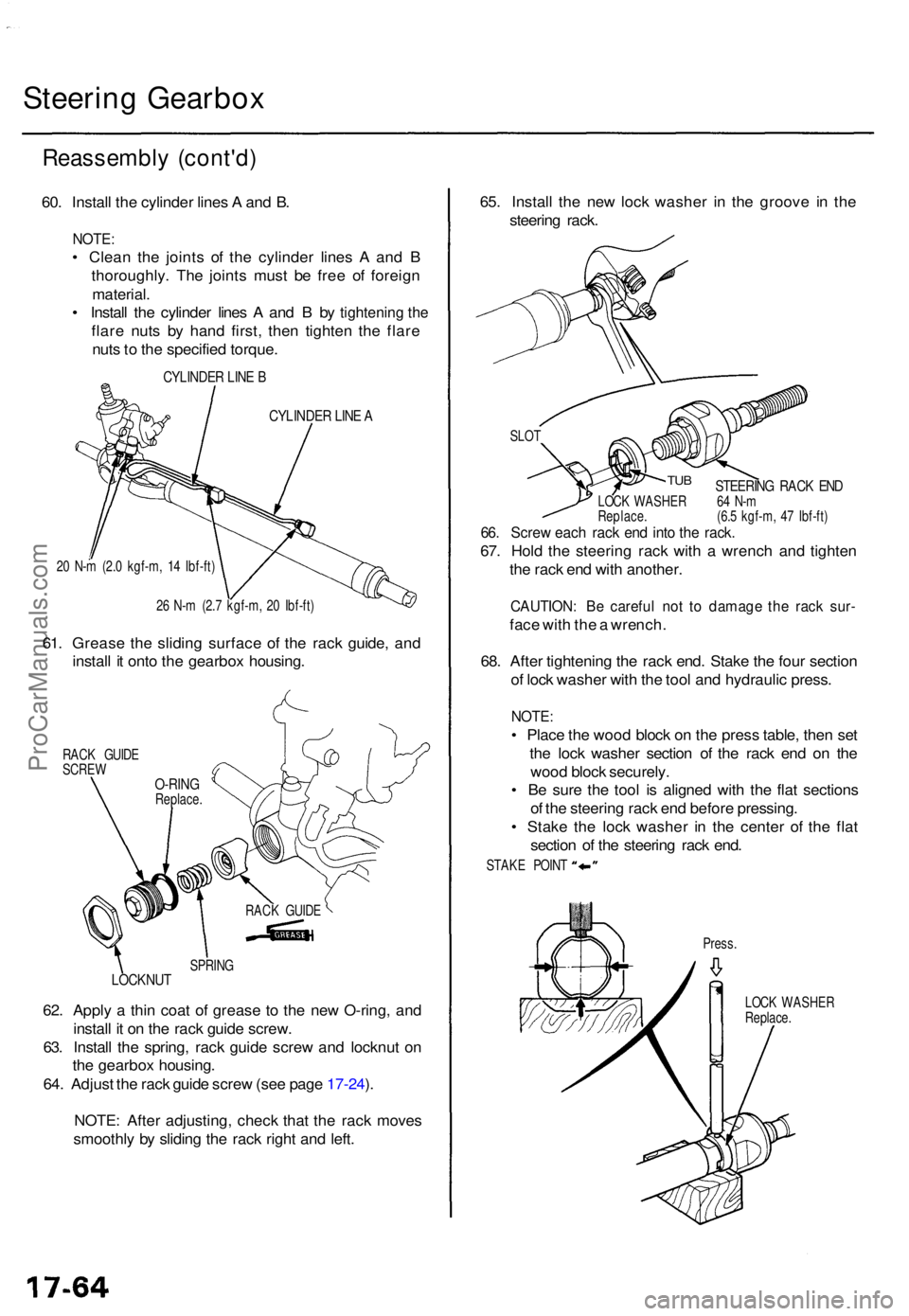
60. Instal l th e cylinde r line s A an d B .
NOTE :
• Clea n th e joint s o f th e cylinde r line s A an d B
thoroughly . Th e joint s mus t b e fre e o f foreig n
material .
• Instal l th e cylinde r line s A an d B by
tightening the
flar e nut s b y han d first , the n tighte n th e flar e
nut s t o th e specifie d torque .
CYLINDE R LIN E B
CYLINDE R LIN E A
20 N- m (2. 0 kgf-m , 1 4 Ibf-ft )
2 6 N- m (2. 7 kgf-m , 2 0 Ibf-ft )
61. Greas e th e slidin g surfac e o f th e rac k guide , an d
instal l i t ont o th e gearbo x housing .
RACK GUID E
SCRE W
SPRING
LOCKNU T
62. Appl y a thi n coa t o f greas e t o th e ne w O-ring , an d
instal l i t o n th e rac k guid e screw .
63 . Instal l th e spring , rac k guid e scre w an d locknu t o n
th e gearbo x housing .
64 . Adjus t th e rac k guid e scre w (se e pag e 17-24 ).
NOTE : Afte r adjusting , chec k tha t th e rac k move s
smoothl y b y slidin g th e rac k righ t an d left . 65
. Instal l th e ne w loc k washe r i n th e groov e i n th e
steerin g rack .
STEERIN G RAC K EN DLOC K WASHE R 6 4 N- m
Replace . (6. 5 kgf-m , 4 7 Ibf-ft )
66. Scre w eac h rac k en d int o th e rack .
67. Hol d th e steerin g rac k wit h a wrenc h an d tighte n
th e rac k en d wit h another .
CAUTION : B e carefu l no t t o damag e th e rac k sur -
face wit h th e a wrench .
68 . Afte r tightenin g th e rac k end . Stak e th e fou r sectio n
o f loc k washe r wit h th e too l an d hydrauli c press .
NOTE:
• Plac e th e woo d bloc k o n th e pres s table , the n se t
th e loc k washe r sectio n o f th e rac k en d o n th e
woo d bloc k securely .
• B e sur e th e too l i s aligne d wit h th e fla t section s
o f th e steerin g rac k en d befor e pressing .
• Stak e th e loc k washe r i n th e cente r o f th e fla t
sectio n o f th e steerin g rac k end .
Press .
LOC K WASHE R
Replace .
RAC
K GUID E
O-RINGReplace .
TUB
SLO T
STAK E POIN T
ProCarManuals.com
Page 1210 of 1771
Steering Gearbo x
Reassembl y (cont'd )
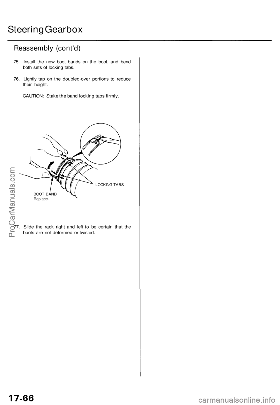
75. Instal l th e ne w boo t band s o n th e boot , an d ben d
bot h set s o f lockin g tabs .
76 . Lightl y ta p o n th e doubled-ove r portion s t o reduc e
thei r height .
CAUTION : Stak e th e ban d lockin g tab s firmly .
LOCKIN G TAB S
BOO T BAN D
Replace .
77. Slid e th e rac k righ t an d lef t t o b e certai n tha t th e
boot s ar e no t deforme d o r twisted .
ProCarManuals.com
Page 1211 of 1771
Steering Gearbo x
Installatio n
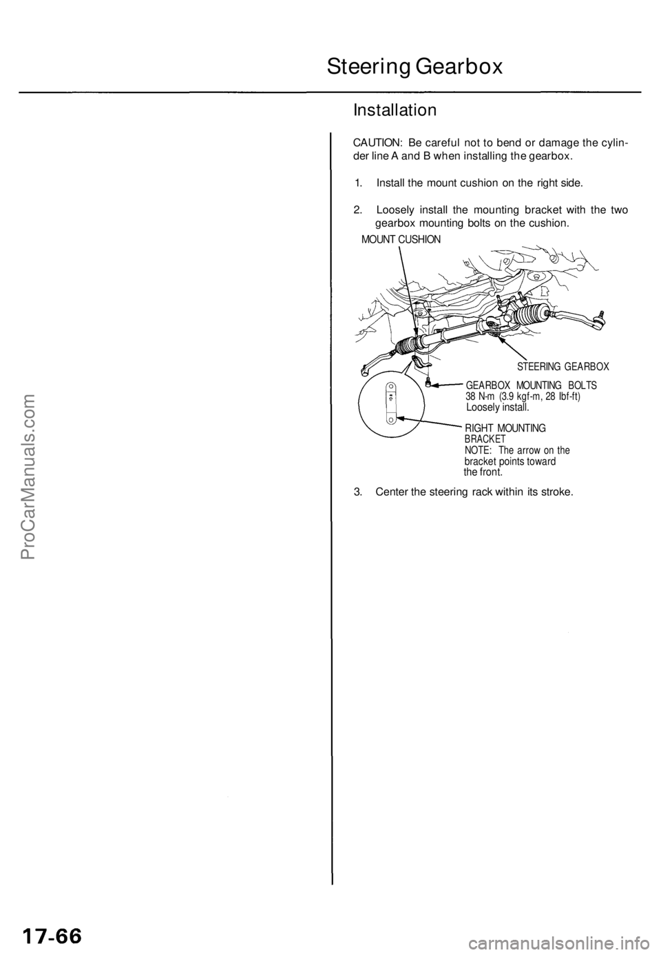
CAUTION: B e carefu l no t t o ben d o r damag e th e cylin -
de r lin e A an d B whe n installin g th e gearbox .
1 . Instal l th e moun t cushio n o n th e righ t side .
2 . Loosel y instal l th e mountin g bracke t wit h th e tw o
gearbo x mountin g bolt s o n th e cushion .
MOUNT CUSHIO N
STEERIN G GEARBO X
GEARBO X MOUNTIN G BOLT S
3 8 N- m (3. 9 kgf-m , 2 8 Ibf-ft )
Loosel y install .
RIGHT MOUNTIN GBRACKETNOTE: Th e arro w o n th ebracke t point s towar dthe front .
3. Cente r th e steerin g rac k withi n it s stroke .
ProCarManuals.com
Page 1213 of 1771
Steering Gearbo x
Installatio n (cont'd )
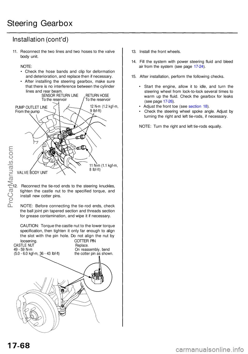
11. Reconnec t th e tw o line s an d tw o hose s t o th e valv e
body unit .
NOTE :
• Chec k th e hos e band s an d cli p fo r deformatio n
an d deterioration , an d replac e the n if necessary .
• Afte r installin g th e steerin g gearbox , mak e sur e
tha t ther e is n o interferenc e betwee n th e cylinde r
line s an d rea r beam .
PUMP OUTLE T LIN EFrom th e pum p
12 N- m (1. 2 kgf-m ,9 Ibf-ft )
VALV E BOD Y UNI T
11 N- m (1. 1 kgf-m ,8 Ibf-ft )
12. Reconnec t th e tie-ro d end s t o th e steerin g knuckles ,
tighte n th e castl e nu t t o th e specifie d torque , an d
instal l ne w cotte r pins .
NOTE : Befor e connectin g th e tie-ro d ends , chec k
th e bal l join t pi n tapere d sectio n an d thread s sectio n
fo r greas e contamination , an d wip e it i f necessary .
CAUTION : Torqu e th e castl e nu t t o th e lowe r torqu e
specification , the n tighte n it onl y fa r enoug h t o alig n
th e slo t wit h th e pi n hole . D o no t alig n th e nu t b y
loosening . COTTER PI NCASTL E NU T Replace.49 - 5 9 N- m O n reassembly , ben d(5.0 - 6. 0 kgf-m , 3 6 - 4 3 Ibf-ft ) th e cotte r pi n a s shown .
13. Instal l th e fron t wheels .
14 . Fil l th e syste m wit h powe r steerin g flui d an d blee d
ai r fro m th e syste m (se e pag e 17-24 ).
15 . Afte r installation , perfor m th e followin g checks .
• Star t th e engine , allo w i t t o idle , an d tur n th e
steerin g whee l fro m lock-to-loc k severa l time s t o
war m u p th e fluid . Chec k th e gearbo x fo r leak s
(se e pag e 17-26 ).
• Adjus t th e fron t to e (se e sectio n 18 ).
• Chec k th e steerin g whee l spok e angle . Adjus t b y
turnin g th e righ t an d lef t tie-rods , i f necessary .
NOTE : Tur n th e righ t an d lef t tie-rod s equally .
SENSO R RETUR N LIN ETo th e reservoi rRETURN HOS ETo th e reservoi r
ProCarManuals.com