Page 1225 of 1771

Front Suspensio n
Knuckle/Hu b (cont'd )
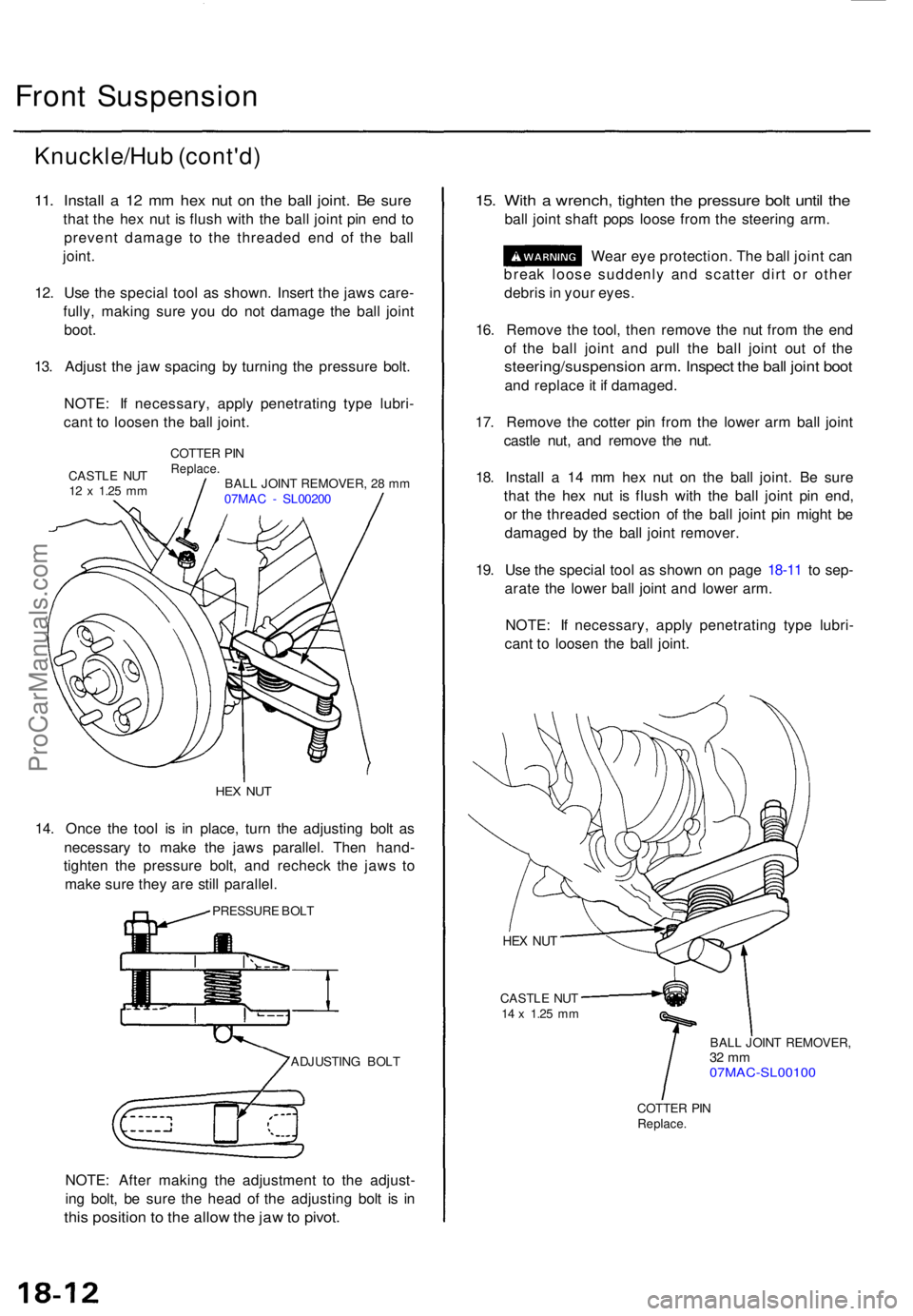
11. Instal l a 12 m m he x nu t o n th e bal l joint . B e sur e
that th e he x nu t i s flus h wit h th e bal l join t pi n en d t o
preven t damag e t o th e threade d en d o f th e bal l
joint .
12 . Us e th e specia l too l a s shown . Inser t th e jaw s care -
fully , makin g sur e yo u d o no t damag e th e bal l join t
boot .
13 . Adjus t th e ja w spacin g b y turnin g th e pressur e bolt .
NOTE : I f necessary , appl y penetratin g typ e lubri -
can t t o loose n th e bal l joint .
CASTL E NU T12 x 1.2 5 mm
COTTE R PI NReplace .BALL JOIN T REMOVER , 2 8 m m
07MA C - SL0020 0
HEX NU T
14. Onc e th e too l i s i n place , tur n th e adjustin g bol t a s
necessar y t o mak e th e jaw s parallel . The n hand -
tighte n th e pressur e bolt , an d rechec k th e jaw s t o
mak e sur e the y ar e stil l parallel .
PRESSUR E BOL T
ADJUSTIN G BOL T
NOTE : Afte r makin g th e adjustmen t t o th e adjust -
in g bolt , b e sur e th e hea d o f th e adjustin g bol t i s i n
thi s positio n t o th e allo w th e ja w to pivot .
15. Wit h a wrench , tighte n th e pressur e bol t unti l th e
bal l join t shaf t pop s loos e fro m th e steerin g arm .
Wea r ey e protection . Th e bal l join t ca n
brea k loos e suddenl y an d scatte r dir t o r othe r
debri s in you r eyes .
16 . Remov e th e tool , the n remov e th e nu t fro m th e en d
o f th e bal l join t an d pul l th e bal l join t ou t o f th e
steering/suspensio n arm . Inspec t th e bal l join t boo t
and replac e it i f damaged .
17 . Remov e th e cotte r pi n fro m th e lowe r ar m bal l join t
castl e nut , an d remov e th e nut .
18 . Instal l a 1 4 m m he x nu t o n th e bal l joint . B e sur e
tha t th e he x nu t i s flus h wit h th e bal l join t pi n end ,
o r th e threade d sectio n o f th e bal l join t pi n migh t b e
damage d b y th e bal l join t remover .
19 . Us e th e specia l too l a s show n o n pag e 18-1 1 t o sep -
arat e th e lowe r bal l join t an d lowe r arm .
NOTE : I f necessary , appl y penetratin g typ e lubri -
can t t o loose n th e bal l joint .
HEX NU T
CASTL E NU T14 x 1.2 5 mm
BAL L JOIN T REMOVER ,32 m m07MAC-SL0010 0
COTTER PI NReplace .
ProCarManuals.com
Page 1552 of 1771
Steering Loc k Replacemen t
SRS component s ar e locate d in thi s area . Revie w th e SR S
componen t locations , precautions , an d procedure s i n th e
SR S (sectio n 24 ) befor e performin g repair s o r service .
Removal :
1 . Mak e sur e yo u hav e th e anti-thef t cod e fo r th e radio ,
then writ e dow n th e frequencie s fo r th e radio' s pre -
set buttons .
2. Disconnec t th e batter y negativ e cable , the n disconnec t
th e positiv e cable , an d wai t a t leas t thre e minutes .
3 . Remov e th e dashboar d lowe r cove r an d kne e bolster .
KNEEBOLSTE R
DASHBOARD LOWE R COVE R
4. Remov e th e steerin g colum n covers .
STEERIN G COLUM NUPPER COVE R
STEERIN GCOLUMNLOWERCOVER
5. Disconnec t th e connector s fro m th e switch .
SWITCH
HARNES S
IGNITIO N SWITC H
7 P CONNECTO R7
P CONNECTO R
ProCarManuals.com
Page 1553 of 1771
Ignition Switch
Steering Lock Replacement (cont'd)
6. Remove the column holder mounting bolts and nuts.
16 N-m
(1.6 kgf-m, 12 Ibf-ft)
COLUMN
HOLDER
38 N-m
(3.9 kgf-m, 28 Ibf-ft)
7. Lower the steering column assembly.
8. Center-punch each of the two shear bolts, and drill
their heads off with a 5 mm (3/16 in) drill bit.
CAUTION: Do not damage the switch body when
removing the shear bolts.
9. Remove the shear bolts from the switch body, then
remove the steering lock assembly.
Installation:
1. Install the new ignition switch without the key
inserted.
2. Loosely tighten the new shear bolts.
3. Insert the ignition key, and check for proper opera-
tion of the steering wheel lock and that the ignition
key turns freely.
4. Tighten the shear bolts until the hex heads twist off.
SHEAR BOLT
TWIST-OFF PORTION
5. Install in the reverse order of removal.
6. Enter the anti-theft code for the radio, then enter the
customer's radio station presets.ProCarManuals.com
Page 1636 of 1771

Lighting Syste m
Front Parkin g Ligh t
Combinatio n Ligh t Switc h
Replacemen t
SRS component s ar e locate d i n thi s area . Revie w th e
SR S componen t locations , precautions , an d procedure s
i n th e SR S (sectio n 24 ) befor e performin g repair s o r ser -
vice .
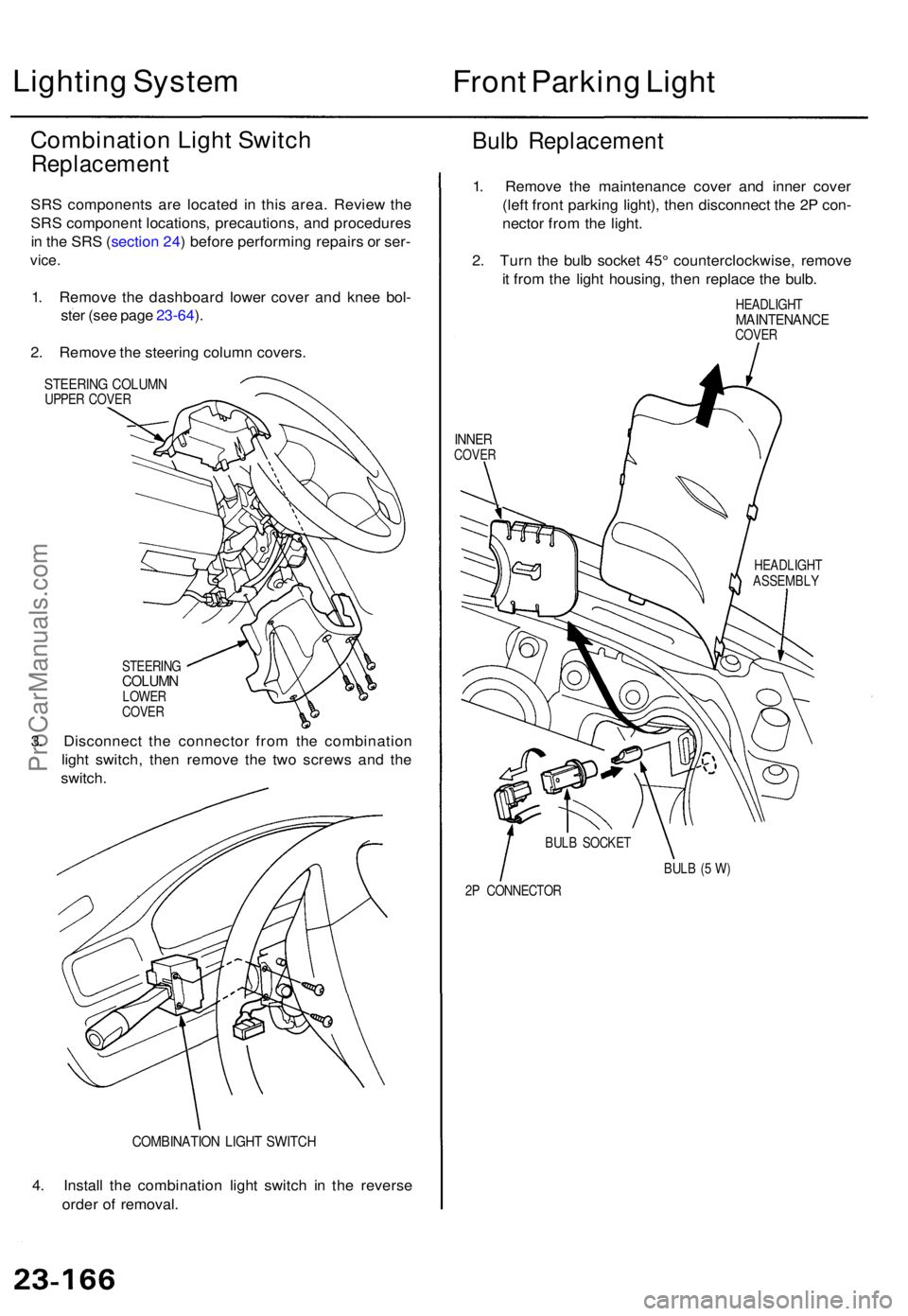
1. Remov e th e dashboar d lowe r cove r an d kne e bol -
ste r (se e pag e 23-64 ).
2 . Remov e th e steerin g colum n covers .
STEERIN G COLUM NUPPER COVE R
Bulb Replacemen t
STEERINGCOLUMNLOWER
COVE R
3. Disconnec t th e connecto r fro m th e combinatio n
ligh t switch , the n remov e th e tw o screw s an d th e
switch .
COMBINATIO N LIGH T SWITC H
4. Instal l th e combinatio n ligh t switc h i n th e revers e
orde r o f removal . 1
. Remov e th e maintenanc e cove r an d inne r cove r
(lef t fron t parkin g light) , the n disconnec t th e 2 P con -
necto r fro m th e light .
2 . Tur n th e bul b socke t 45 ° counterclockwise , remov e
i t fro m th e ligh t housing , the n replac e th e bulb .
HEADLIGH TMAINTENANC ECOVER
INNERCOVE R
HEADLIGH T
ASSEMBL Y
BUL B (5 W )
2 P CONNECTO R
BUL
B SOCKE T
ProCarManuals.com
Page 1746 of 1771

Steering-related Precautions
Steering Whee l an d Cabl e Ree l Alignmen t
NOTE : T o avoi d misalignmen t o f th e steerin g whee l o n
reassembly , mak e sur e th e wheel s ar e turne d straigh t
ahea d befor e removin g th e steerin g wheel .
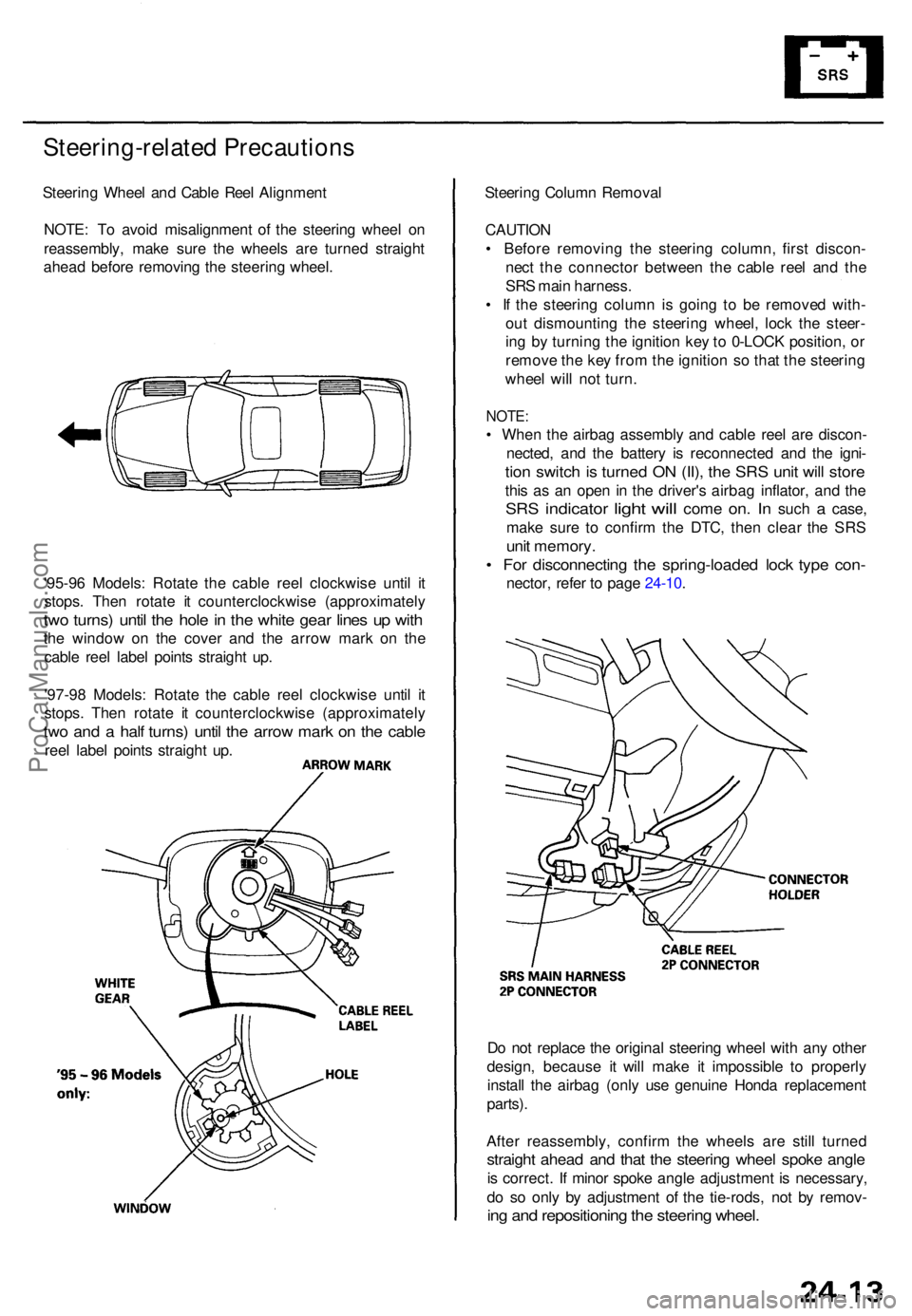
'95-9 6 Models : Rotat e th e cabl e ree l clockwis e unti l i t
stops . The n rotat e i t counterclockwis e (approximatel y
two turns ) unti l th e hol e in th e whit e gea r line s u p wit h
the windo w o n th e cove r an d th e arro w mar k o n th e
cabl e ree l labe l point s straigh t up .
'97-9 8 Models : Rotat e th e cabl e ree l clockwis e unti l i t
stops . The n rotat e i t counterclockwis e (approximatel y
two an d a hal f turns ) unti l th e arro w mar k o n th e cabl e
reel labe l point s straigh t up . Steerin
g Colum n Remova l
CAUTIO N
• Befor e removin g th e steerin g column , firs t discon -
nec t th e connecto r betwee n th e cabl e ree l an d th e
SR S mai n harness .
• I f th e steerin g colum n i s goin g t o b e remove d with -
ou t dismountin g th e steerin g wheel , loc k th e steer -
in g b y turnin g th e ignitio n ke y to 0-LOC K position , o r
remov e th e ke y fro m th e ignitio n s o tha t th e steerin g
whee l wil l no t turn .
NOTE :
• Whe n th e airba g assembl y an d cabl e ree l ar e discon -
nected , an d th e batter y i s reconnecte d an d th e igni -
tion switc h is turne d O N (II) , th e SR S uni t wil l stor e
this a s a n ope n i n th e driver' s airba g inflator , an d th e
SR S indicato r light will com e on. I n suc h a case ,
mak e sur e t o confir m th e DTC , the n clea r th e SR S
unit memory .
• Fo r disconnectin g th e spring-loade d loc k typ e con -
nector , refe r t o pag e 24-10 .
D o no t replac e th e origina l steerin g whee l wit h an y othe r
design , becaus e i t wil l mak e i t impossibl e t o properly
instal l th e airba g (onl y us e genuin e Hond a replacemen t
parts) .
Afte r reassembly , confir m th e wheel s ar e stil l turne d
straight ahea d an d tha t th e steerin g whee l spok e angl e
is correct . I f mino r spok e angl e adjustment is necessary ,
d o s o onl y b y adjustmen t o f th e tie-rods , no t b y remov -
ing an d repositionin g th e steerin g wheel .
ProCarManuals.com
Page 1771 of 1771

SUPPLEMENTAL RESTRAINT SYSTEMThe Acura TL SRS includes a driver's airbag located in the steering wheel hub and a passenger's airbag located in the dashboard above
the glove box. Information necessary to safely service the SRS is included in this Service Manual. Items marked with an asterisk (*) on
the contents page include, or are located near, SRS components. Servicing, disassembling or replacing these items will require special
precautions and tools, and should therefore be done by an authorized Honda dealer.
WARNING
�To avoid rendering the SRS inoperative, which could lead to personal injury or death in the event of a severe frontal
collision, all SRS service work must be performed by an authorized Honda dealer.
�Improper service procedures, including incorrect removal and installation of the SRS, could lead to personal injury
caused by unintentional activation of the front airbags, seat belt tensioners, and side airbags ('99-01 models).
�Do not bump the SRS unit. Otherwise, the system may fail in a collision, or the airbags may deploy when the ignition
switch in ON (II).
�All SRS electrical wiring harnesses are covered with yellow insulation. Related components are located in the steering
column, front console, dashboard, dashboard lower panel, in the dashboard above the glove box. Do not use electrical
test equipment on these circuits.
NOTE: The original radio has a coded theft protection circuit. Be sure to get the customer's code number before
± disconnecting the battery.
± removing the No. 39 (10A) fuse from the under±hood fuse/relay box.
± removing the radio.
After service, reconnect power to the radio and turn it on. When the word ºCODEº is displayed, enter the customer's 5-digit code to restore
radio operation.
ProCarManuals.com