1995 ACURA TL steering
[x] Cancel search: steeringPage 474 of 1771
Steering Gearbo x
Remova l (cont'd )
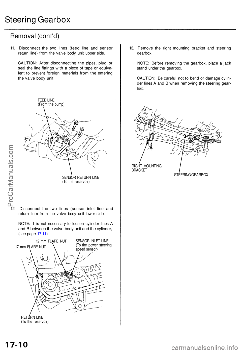
11. Disconnec t th e tw o line s (fee d lin e an d senso r
retur n line ) fro m th e valv e bod y uni t uppe r side .
CAUTION : Afte r disconnectin g th e pipes , plu g o r
sea l th e lin e fitting s wit h a piec e o f tap e o r equiva -
len t t o preven t foreig n material s fro m th e enterin g
th e valv e bod y unit :
FEED LIN E(Fro m th e pump )
SENSO R RETUR N LIN E
(T o th e reservoir )
12. Disconnec t th e tw o line s (senso r inle t lin e an d
retur n line ) fro m th e valv e bod y uni t lowe r side .
NOTE : I t i s no t necessar y t o loose n cylinde r line s A
an d B betwee n th e valv e bod y uni t an d th e cylinder ,
(see pag e 17-11 )
12 m m FLAR E NU T
17 m m FLAR E NU T SENSO
R INLE T LIN E
(T o th e powe r steerin g
spee d sensor )
RETUR N LIN E
(T o th e reservoir )
13. Remov e th e righ t mountin g bracke t an d steerin g
gearbox .
NOTE : Befor e removin g th e gearbox , plac e a jac k
stan d unde r th e gearbox.
CAUTION : B e carefu l no t t o ben d o r damag e cylin -
de r line s A an d B whe n removin g th e steerin g gear -
box.
RIGH T MOUNTIN GBRACKET
STEERIN G GEARBO X
ProCarManuals.com
Page 475 of 1771
Disassembly
Steering Rac k Disassembl y
NOTE:
• Befor e disassemblin g th e gearbox , was h i t of f wit h
solven t an d a brush .
• D o no t di p seal s an d O-ring s i n solvent .
1 . Remov e th e steerin g gearbo x (se e pag e 17-9 ).
2 . Remov e th e tie-ro d en d an d locknut .
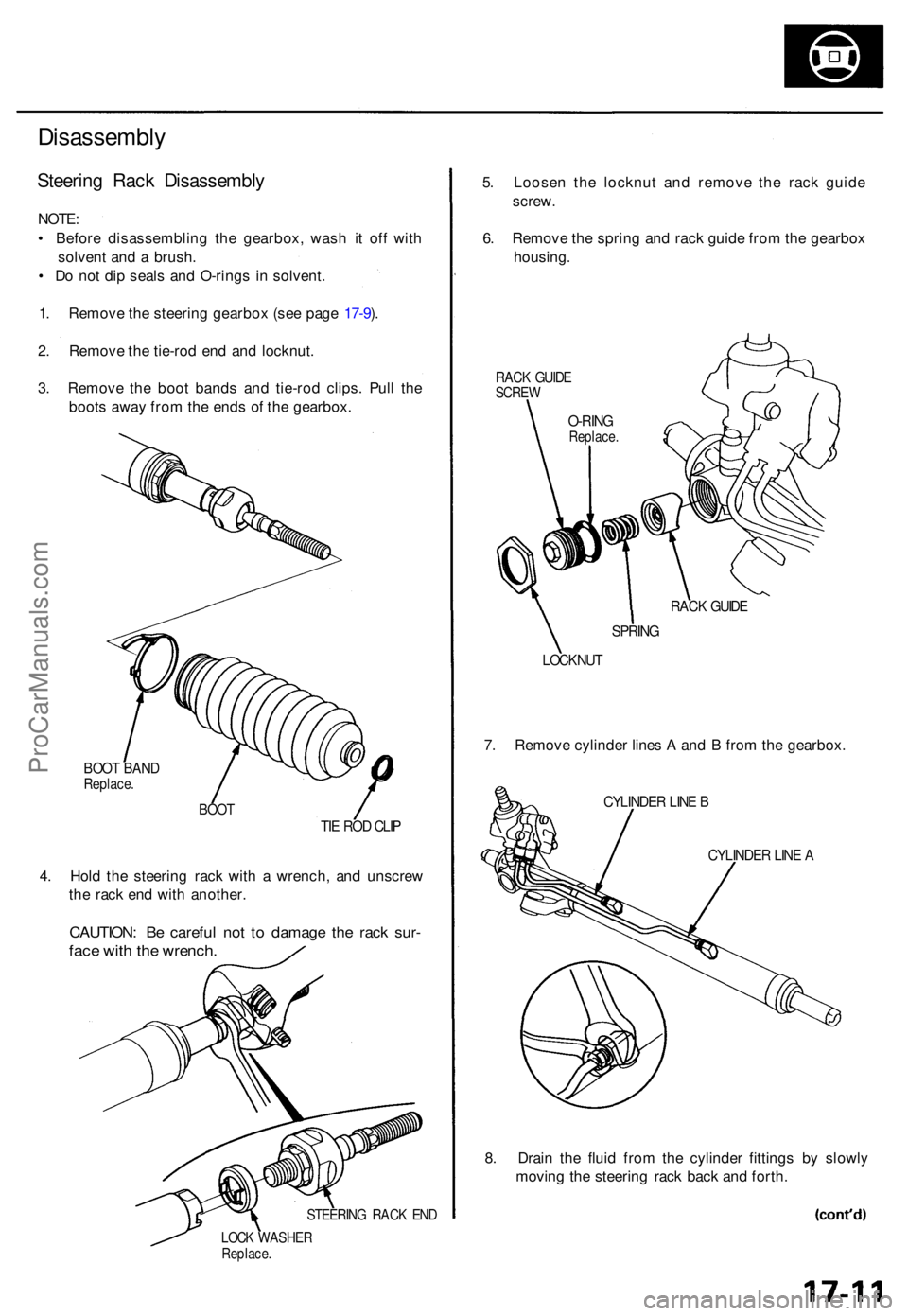
3 . Remov e th e boo t band s an d tie-ro d clips . Pul l th e
boot s awa y fro m th e end s o f th e gearbox .
BOOT BAN DReplace .
BOOTTIE RO D CLI P
4. Hol d th e steerin g rac k wit h a wrench , an d unscre w
th e rac k en d wit h another .
CAUTION : B e carefu l no t t o damag e th e rac k sur -
face wit h th e wrench .
STEERIN G RAC K EN D
LOC K WASHE RReplace.
5. Loose n th e locknu t an d remov e th e rac k guid e
screw .
6 . Remov e th e sprin g an d rac k guid e fro m th e gearbo x
housing .
RACK GUID ESCRE W
RACK GUID E
SPRIN G
LOCKNU T
7. Remov e cylinde r line s A an d B fro m th e gearbox .
CYLINDER LIN E B
CYLINDE R LIN E A
8. Drai n th e flui d fro m th e cylinde r fitting s b y slowl y
movin g th e steerin g rac k bac k an d forth .
O-RIN GReplace .
ProCarManuals.com
Page 476 of 1771
Steering Gearbo x
Disassembl y (cont'd )
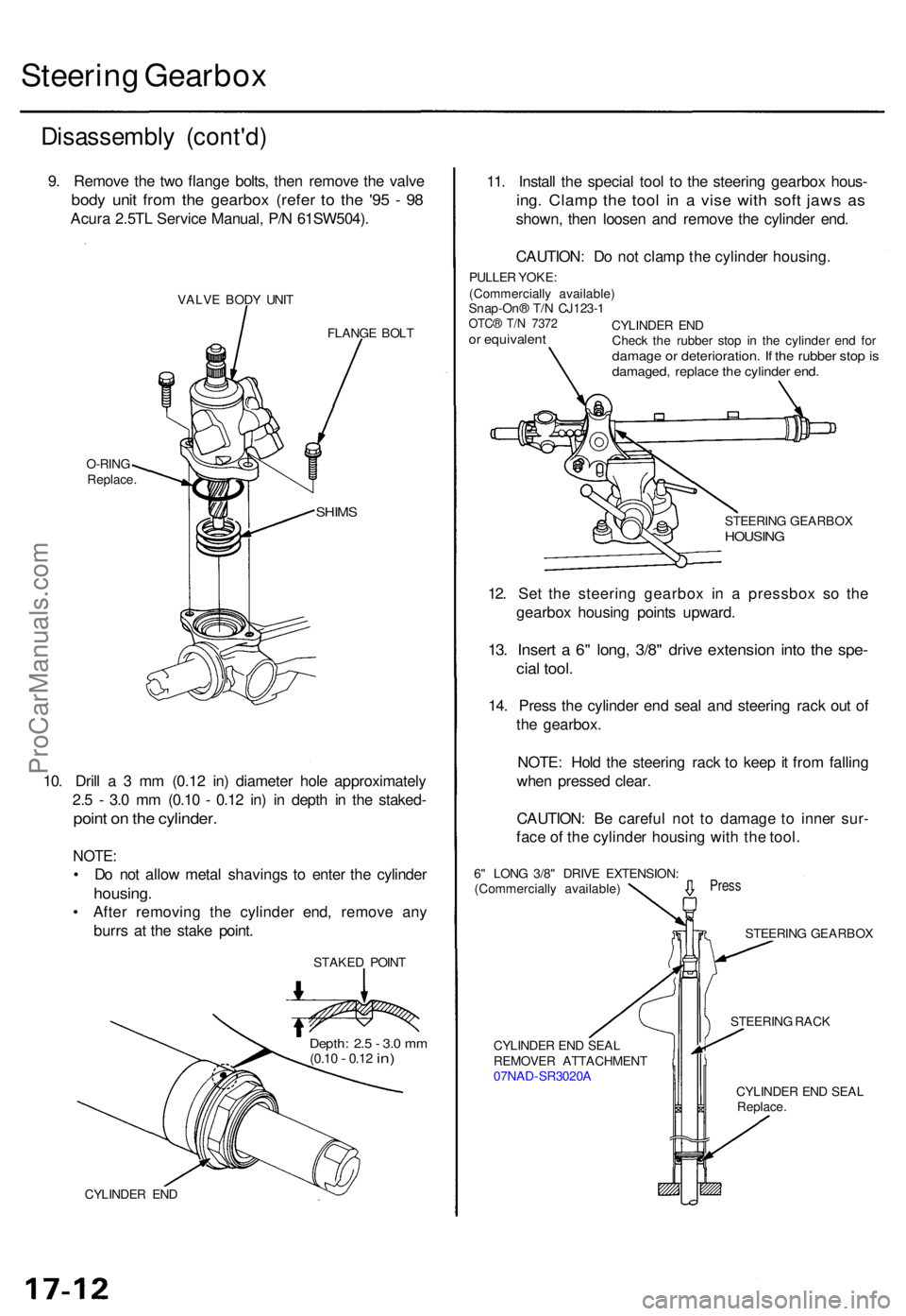
9. Remov e th e tw o flang e bolts , the n remov e th e valv e
body uni t fro m th e gearbo x (refe r t o th e '9 5 - 9 8
Acur a 2.5T L Servic e Manual , P/ N 61SW504) .
VALVE BOD Y UNI T
FLANGE BOL T
10. Dril l a 3 m m (0.1 2 in ) diamete r hol e approximatel y
2. 5 - 3. 0 m m (0.1 0 - 0.1 2 in ) i n dept h i n th e staked -
point o n th e cylinder .
NOTE:
• D o no t allo w meta l shaving s t o ente r th e cylinde r
housing .
• Afte r removin g th e cylinde r end , remov e an y
burr s a t th e stak e point .
STAKE D POIN T
CYLINDE R EN D
11. Instal l th e specia l too l t o th e steerin g gearbo x hous -
ing. Clam p th e too l i n a vis e wit h sof t jaw s a s
shown , the n loose n an d remov e th e cylinde r end .
CAUTION : D o no t clam p th e cylinde r housing .
PULLER YOKE :
(Commerciall y available )
Snap-On ® T/ N CJ123- 1
OTC® T/ N 737 2or equivalen t
STEERING GEARBO XHOUSING
STEERIN G RAC K
CYLINDE R EN D SEA L
REMOVE R ATTACHMEN T
07NA D-SR3020 A
CYLINDER EN D SEA L
Replace .
SHIMS
O-RIN G
Replace . CYLINDE
R EN D
Chec k th e rubbe r sto p i n th e cylinde r en d fo r
damag e o r deterioration . I f th e rubbe r sto p isdamaged , replac e th e cylinde r end .
Depth : 2. 5 - 3. 0 m m(0.1 0 - 0.12 in)
12. Se t th e steerin g gearbo x i n a pressbo x s o th e
gearbo x housin g point s upward .
13. Inser t a 6" long , 3/8 " driv e extensio n int o th e spe -
cial tool .
14. Pres s th e cylinde r en d sea l an d steerin g rac k ou t o f
th e gearbox .
NOTE : Hol d th e steerin g rac k t o kee p it fro m fallin g
whe n presse d clear .
CAUTION : B e carefu l no t t o damag e t o inne r sur -
fac e o f th e cylinde r housin g wit h th e tool .
Pres s
STEERIN G GEARBO X
6
" LON G 3/8 " DRIV E EXTENSION :
(Commerciall y available )
ProCarManuals.com
Page 478 of 1771
Steering Gearbo x
Disassembl y (cont'd )
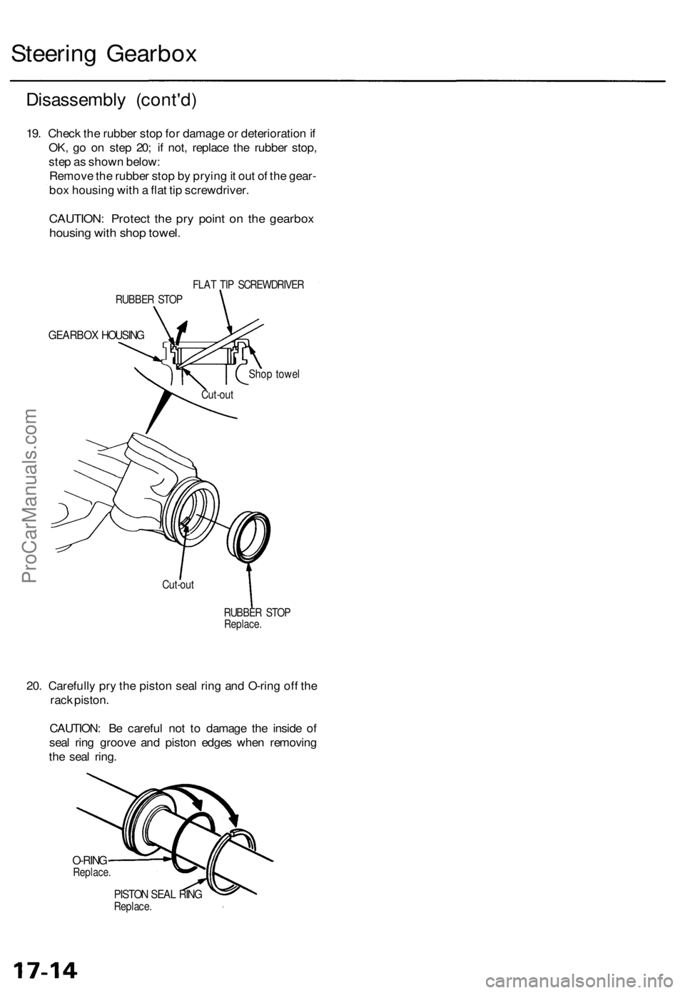
19. Chec k th e rubbe r sto p fo r damag e o r deterioratio n if
OK , g o o n ste p 20 ; i f not , replac e th e rubbe r stop ,
ste p a s show n below :
Remov e th e rubbe r sto p b y pryin g it ou t o f th e gear -
bo x housin g wit h a fla t ti p screwdriver .
CAUTION: Protec t th e pr y poin t o n th e gearbo x
housing wit h sho p towel .
FLAT TI P SCREWDRIVE R
GEARBOX HOUSIN G
Shop towe l
RUBBE R STO P
Replace .
20. Carefull y pr y th e pisto n sea l rin g an d O-rin g of f th e
rac k piston .
CAUTION : B e carefu l no t t o damag e th e insid e o f
sea l rin g groov e an d pisto n edge s whe n removin g
th e sea l ring .
O-RIN GReplace .
PISTON SEA L RIN GReplace .
RUBBE
R STO P
Cut-ou t
Cut-ou t
ProCarManuals.com
Page 479 of 1771
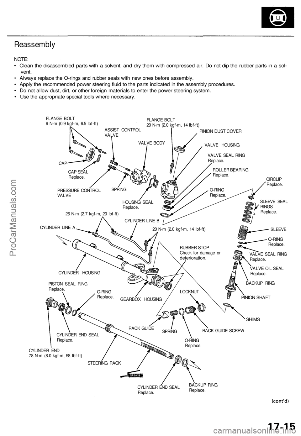
Reassembly
NOTE:
• Clean the disassembled parts with a solvent, and dry them with compressed air. Do not dip the rubber parts in a sol-
vent.
• Always replace the O-rings and rubber seals with new ones before assembly.
• Apply the recommended power steering fluid to the parts indicated in the assembly procedures.
• Do not allow dust, dirt, or other foreign materials to enter the power steering system.
• Use the appropriate special tools where necessary.
FLANGE BOLT
9 N-m (0.9 kgf-m, 6.5 Ibf-ft)
FLANGE BOLT
20 N-m (2.0 kgf-m, 14 Ibf-ft)
CAP
PINION DUST COVER
VALVE HOUSING
26 N-m (2.7 kgf-m, 20 Ibf-ft)
CYLINDER LINE A
VALVE OIL SEAL
Replace.
SHIMS
CYLINDER END
78 N-m (8.0 kgf-m, 58 Ibf-ft)
CYLINDER END SEAL
Replace.
BACKUP RING
Replace.
CAP SEAL
Replace.
PRESSURE CONTROL
VALVE
SPRING
HOUSING SEAL
Replace.
CYLINDER LINE B
VALVE BODY
ASSIST CONTROL
VALVE
VALVE SEAL RING
Replace.
ROLLER BEARING
Replace.
O-RING
Replace.
SLEEVE SEAL
RINGS
Replace.
CIRCLIP
Replace.
SLEEVE
20 N-m (2.0 kgf-m, 14 Ibf-ft)
BACKUP RING
PINION SHAFT
LOCKNUT
RACK GUIDE SCREW
O-RING
Replace.
SPRING
RACK GUIDE
STEERING RACK
CYLINDER END SEAL
Replace.
PISTON SEAL RING
Replace.
CYLINDER HOUSING
GEARBOX HOUSING
O-RING
Replace.
RUBBER STOP
Check for damage or
deterioration.
VALVE SEAL RING
Replace.
O-RING
Replace.ProCarManuals.com
Page 480 of 1771
Steering Gearbo x
Reassembl y (cont'd )
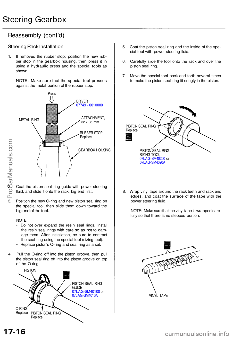
Steering Rac k Installatio n
1. I f remove d th e rubbe r stop ; positio n th e ne w rub -
be r sto p i n th e gearbo x housing , the n pres s i t i n
usin g a hydrauli c pres s an d th e specia l tool s a s
shown .
NOTE : Mak e sur e tha t th e specia l too l presse s
agains t th e meta l portio n o f th e rubbe r stop .
Press
META L RIN G
DRIVE R07749 - 0010000
ATTACHMENT ,32 x 35 m m
RUBBE R STO P
Replace .
GEARBO X HOUSIN G
2. Coa t th e pisto n sea l rin g guid e wit h powe r steerin g
fluid , an d slid e it ont o th e rack , bi g en d first .
3 . Positio n th e ne w O-rin g an d ne w pisto n sea l rin g o n
th e specia l tool , the n slid e the m dow n towar d th e
big en d o f th e tool .
NOTE :
• D o no t ove r expan d th e resi n sea l rings . Instal l
th e resi n sea l ring s wit h car e s o a s no t t o dam -
ag e them . Afte r installation , b e sur e t o contrac t
th e sea l rin g usin g th e specia l too l (sizin g tool) .
• Replac e piston' s O-rin g an d sea l rin g a s a set .
4 . Pul l th e O-rin g of f int o th e pisto n groove , the n pul l
th e pisto n sea l rin g of f int o th e pisto n groov e o n to p
o f th e O-ring .
PISTON
PISTON SEA L RIN GGUID E07LAG-SM4010 0 o r07LA G-SM4010 A
5. Coa t th e pisto n sea l rin g an d th e insid e o f th e spe -
cia l too l wit h powe r steerin g fluid .
6 . Carefull y slid e th e too l ont o th e rac k an d ove r th e
pisto n sea l ring .
7 . Mov e th e specia l too l bac k an d fort h severa l time s
t o mak e th e pisto n sea l rin g fi t snugl y in th e piston .
PISTON SEA L RIN GReplace .
PISTON SEA L RIN GSIZIN G TOO L07LA G-SM4020 0 o r07LA G-SM4020 A
8. Wra p viny l tap e aroun d th e rac k teet h an d rac k en d
edges , an d coa t th e surfac e o f th e tap e wit h th e
powe r steerin g fluid .
NOTE : Mak e sur e tha t th e viny l tap e is wrappe d care -
full y s o tha t ther e is n o steppe d portion .
VINYL TAP E
O-RIN GReplac ePISTON SEA L RIN GReplace .
ProCarManuals.com
Page 482 of 1771
Steering Gearbox
Reassembly (cont'd)
CYLINDER END SEAL
Replace.
VINYL TAPE
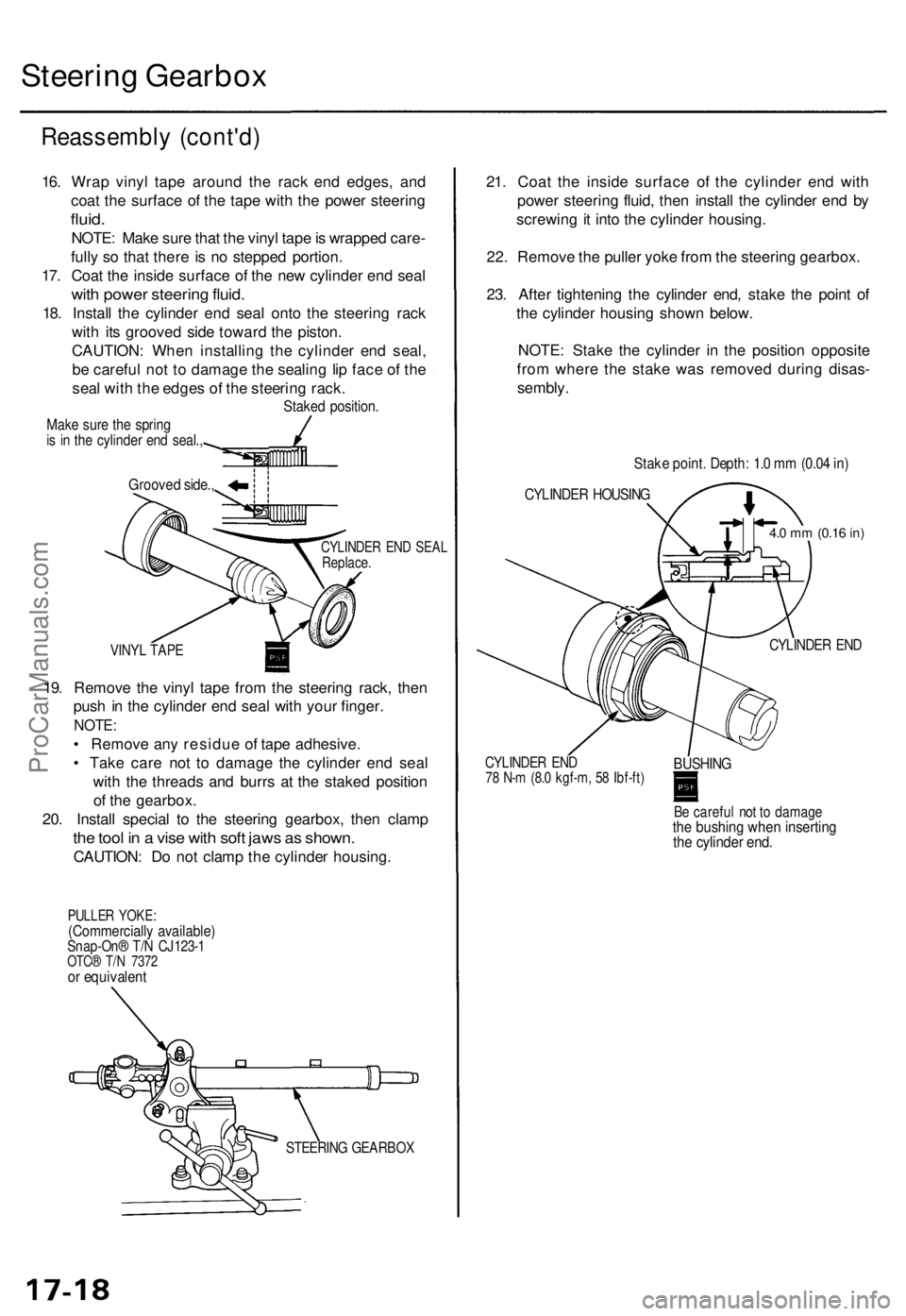
19. Remove the vinyl tape from the steering rack, then
push in the cylinder end seal with your finger.
NOTE:
• Remove any residue of tape adhesive.
• Take care not to damage the cylinder end seal
with the threads and burrs at the staked position
of the gearbox.
20. Install special to the steering gearbox, then clamp
the tool in a vise with soft jaws as shown.
CAUTION: Do not clamp the cylinder housing.
PULLER YOKE:
(Commercially available)
Snap-On® T/N CJ123-1
OTC® T/N 7372
or equivalent
21. Coat the inside surface of the cylinder end with
power steering fluid, then install the cylinder end by
screwing it into the cylinder housing.
22. Remove the puller yoke from the steering gearbox.
23. After tightening the cylinder end, stake the point of
the cylinder housing shown below.
NOTE: Stake the cylinder in the position opposite
from where the stake was removed during disas-
sembly.
CYLINDER END
CYLINDER END
78 N-m (8.0 kgf-m, 58 Ibf-ft)
BUSHING
Be careful not to damage
the bushing when inserting
the cylinder end.
Grooved side.,
Stake point. Depth: 1.0 mm (0.04 in)
CYLINDER HOUSING
4.0 mm
(0.16
in)
STEERING GEARBOX
16. Wrap vinyl tape around the rack end edges, and
coat the surface of the tape with the power steering
fluid.
NOTE: Make sure that the vinyl tape is wrapped care-
fully so that there is no stepped portion.
17. Coat the inside surface of the new cylinder end seal
with power steering fluid.
18. Install the cylinder end seal onto the steering rack
with its grooved side toward the piston.
CAUTION: When installing the cylinder end seal,
be careful not to damage the sealing lip face of the
seal with the edges of the steering rack.
Staked position.
Make sure the spring
is in the cylinder end seal.,ProCarManuals.com
Page 484 of 1771
Steering Gearbo x
Reassembl y (cont'd )
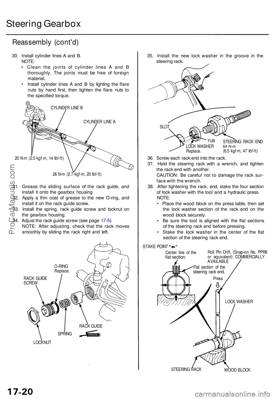
30. Instal l cylinde r line s A an d B .
NOTE :
• Clea n th e joint s o f cylinde r line s A an d B
thoroughly . Th e joint s mus t b e fre e o f foreig n
material .
• Instal l cylinde r line s A an d B by lightin g th e flar e
nut s b y han d first , the n tighte n th e flar e nut s t o
th e specifie d torque .
CYLINDE R LIN E B
CYLINDE R LIN E A
2 0 N- m (2. 0 kgf-m , 1 4 Ibf-ft )
2 6 N- m (2. 7 kgf-m , 2 0 Ibf-ft )
31. Greas e th e slidin g surfac e o f th e rac k guide , an d
instal l i t ont o th e gearbo x housing .
32 . Appl y a thi n coa t o f greas e t o th e ne w O-ring , an d
instal l i t o n th e rac k guid e screw .
33 . Instal l th e spring , rac k guid e scre w an d locknu t o n
th e gearbo x housing .
34 . Adjus t th e rac k guid e scre w (se e pag e 17-5 ).
NOTE : Afte r adjusting , chec k tha t th e rac k move s
smoothl y b y slidin g th e rac k righ t an d left .
RAC K GUID ESCRE W
LOCKNU T
35. Instal l th e ne w loc k washe r i n th e groov e i n th e
steerin g rack .
Cente r lin e o f th eflat section .Roll Pi n Drift , (Snap-o n No . PPR 8
o r equivalent ) COMMERCIALL Y
AVAILABLE
LOCK WASHE R
STEERIN G RAC K
WOOD BLOC K
SLO
T
TUB
36. Scre w eac h rac k en d int o th e rack .
37 . Hol d th e steerin g rac k wit h a wrench , an d tighte n
th e rac k en d wit h another .
CAUTION : B e carefu l no t t o damag e th e rac k sur -
fac e wit h th e wrench .
38 . Afte r tightenin g th e rack , end , stak e th e fou r sectio n
o f loc k washe r wit h th e too l an d a hydrauli c press .
NOTE:
• Plac e th e woo d bloc k o n th e pres s table , the n se t
th e loc k washe r sectio n o f th e rac k en d o n th e
woo d bloc k securely .
• B e sur e th e too l i s aligne d wit h th e fla t section s
o f th e steerin g rac k en d befor e pressing .
• Stak e th e loc k washe r i n th e cente r o f th e fla t
sectio n o f th e steerin g rac k end .
STEERIN G RAC K EN D64 N- m(6.5 kgf-m , 4 7 Ibf-ft )
LOC
K WASHE RReplace.
STAKE POIN T
Flat sectio n o f th e
steerin g rac k end .
Pres s
SPRIN GRAC
K GUID E
O-RIN
G
Replace .
ProCarManuals.com