1995 ACURA TL ignition
[x] Cancel search: ignitionPage 903 of 1771
Fuel Supply System
Fuel Pressure
Relieving (models with service bolt)
Before disconnecting fuel pipes or hoses, release pres-
sure from the system by loosening the 6 mm service
bolt on top of the fuel filter.
Do not smoke while working on the fuel system.
Keep open flames or sparks away from your work
area.
• Be sure to relieve fuel pressure while the ignition
switch is off.
1. Make sure you have the anti-theft code for the radio,
then write down the frequencies for the radio's pre-
set buttons.
2. Disconnect the battery negative cable from the bat-
tery negative terminal.
3.
Remove
the
fuel
fill
cap.
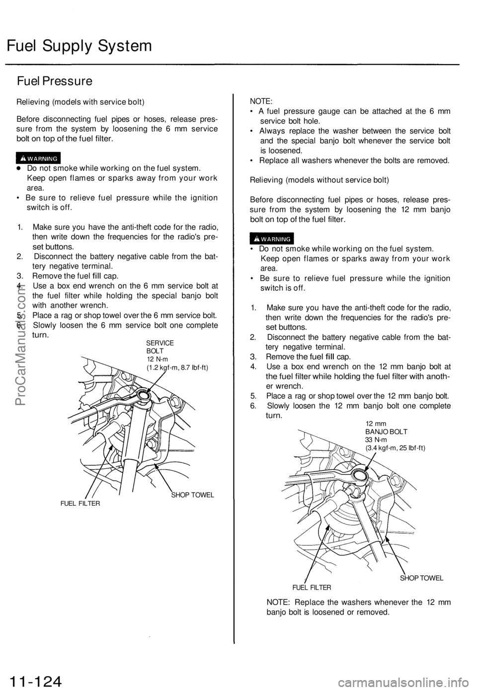
4. Use a box end wrench on the 6 mm service bolt at
the fuel filter while holding the special banjo bolt
with another wrench.
5. Place a rag or shop towel over the 6 mm service bolt.
6. Slowly loosen the 6 mm service bolt one complete
turn.
SERVICE
BOLT
12 N-m
(1.2 kgf-m, 8.7 Ibf-ft)
SHOP TOWEL
FUEL FILTER
NOTE:
• A fuel pressure gauge can be attached at the 6 mm
service bolt hole.
• Always replace the washer between the service bolt
and the special banjo bolt whenever the service bolt
is loosened.
• Replace all washers whenever the bolts are removed.
Relieving (models without service bolt)
Before disconnecting fuel pipes or hoses, release pres-
sure from the system by loosening the 12 mm banjo
bolt on top of the fuel filter.
• Do not smoke while working on the fuel system.
Keep open flames or sparks away from your work
area.
• Be sure to relieve fuel pressure while the ignition
switch is off.
1. Make sure you have the anti-theft code for the radio,
then write down the frequencies for the radio's pre-
set buttons.
2. Disconnect the battery negative cable from the bat-
tery negative terminal.
3.
Remove
the
fuel
fill
cap.
4. Use a box end wrench on the 12 mm banjo bolt at
the fuel filter while holding the fuel filter with anoth-
er wrench.
5. Place a rag or shop towel over the 12 mm banjo bolt.
6. Slowly loosen the 12 mm banjo bolt one complete
turn.
12 mm
BANJO BOLT
33 N-m
(3.4 kgf-m, 25 Ibf-ft)
SHOP TOWEL
FUEL FILTER
NOTE: Replace the washers whenever the 12 mm
banjo bolt is loosened or removed.
11-124ProCarManuals.com
Page 907 of 1771
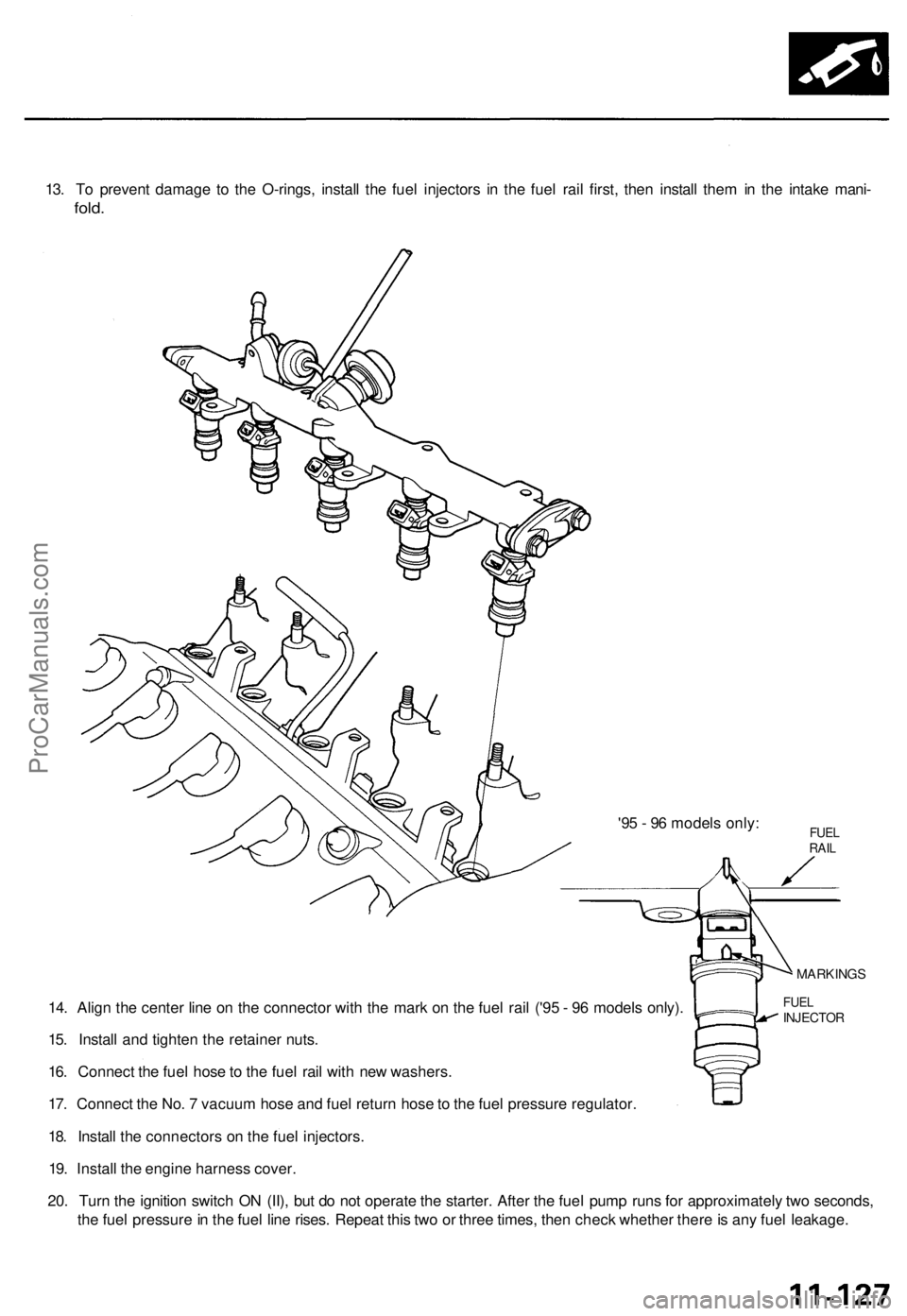
13. To prevent damage to the O-rings, install the fuel injectors in the fuel rail first, then install them in the intake mani-
fold.
'95 - 96 models only:
14. Align the center line on the connector with the mark on the fuel rail ('95 - 96 models only).
15. Install and tighten the retainer nuts.
16. Connect the fuel hose to the fuel rail with new washers.
17. Connect the No. 7 vacuum hose and fuel return hose to the fuel pressure regulator.
18. Install the connectors on the fuel injectors.
19. Install the engine harness cover.
20. Turn the ignition switch ON (II), but do not operate the starter. After the fuel pump runs for approximately two seconds,
the fuel pressure in the fuel line rises. Repeat this two or three times, then check whether there is any fuel leakage.
FUEL
INJECTOR
MARKINGS
FUEL
RAILProCarManuals.com
Page 914 of 1771
PGM-FI Main Relay
Description
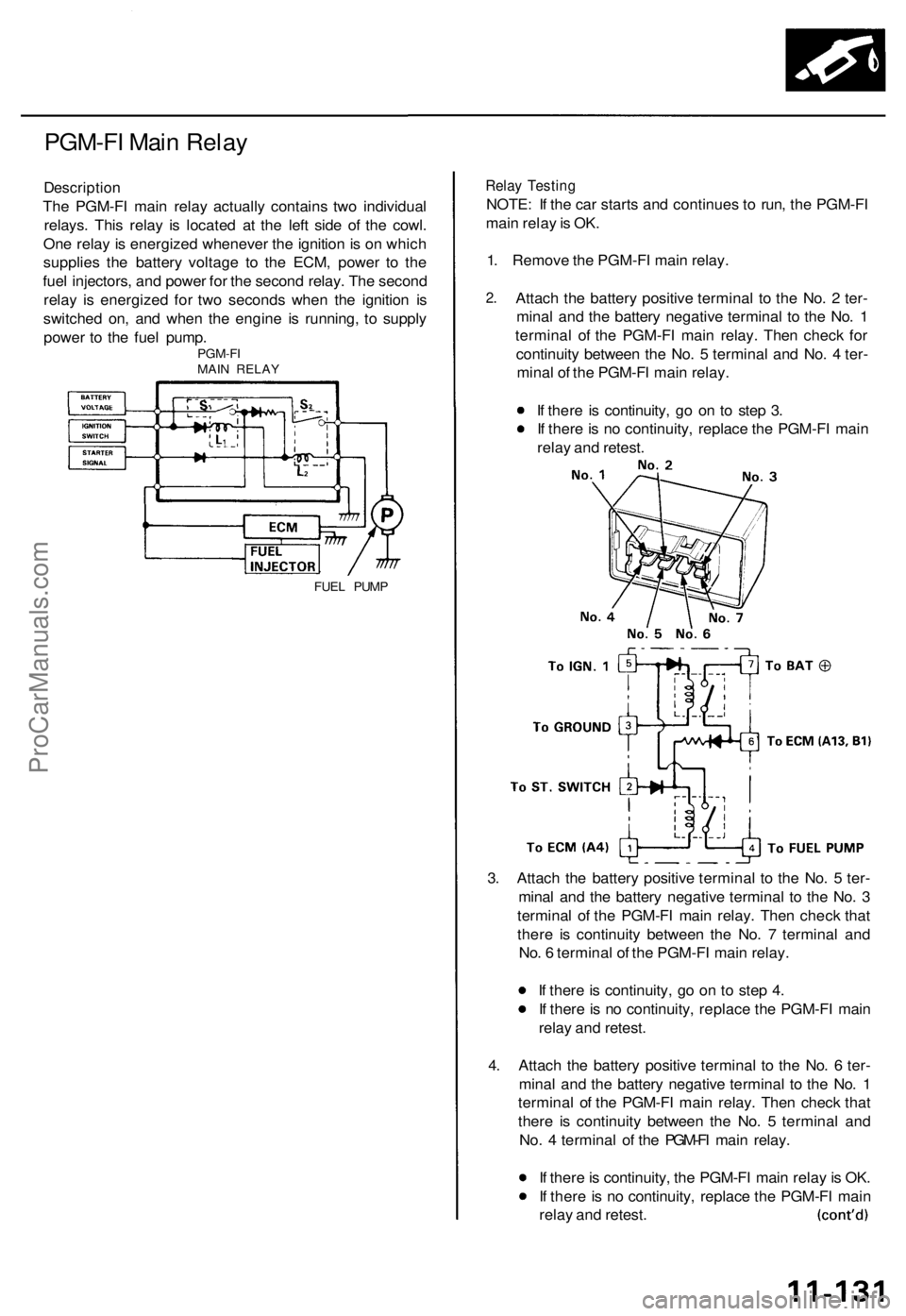
The PGM-FI main relay actually contains two individual
relays. This relay is located at the left side of the cowl.
One relay is energized whenever the ignition is on which
supplies the battery voltage to the ECM, power to the
fuel injectors, and power for the second relay. The second
relay is energized for two seconds when the ignition is
switched on, and when the engine is running, to supply
power to the fuel pump.
PGM-FI
MAIN RELAY
FUEL PUMP
Relay Testing
NOTE: If the car starts and continues to run, the PGM-FI
main relay is OK.
1. Remove the PGM-FI main relay.
2.
Attach the battery positive terminal to the No. 2 ter-
minal and the battery negative terminal to the No. 1
terminal of the PGM-FI main relay. Then check for
continuity between the No. 5 terminal and No. 4 ter-
minal of the PGM-FI main relay.
If there is continuity, go on to step 3.
If there is no continuity, replace the PGM-FI main
relay and retest.
3. Attach the battery positive terminal to the No. 5 ter-
minal and the battery negative terminal to the No. 3
terminal of the PGM-FI main relay. Then check that
there is continuity between the No. 7 terminal and
No. 6 terminal of the PGM-FI main relay.
If there is continuity, go on to step 4.
If there is no continuity, replace the PGM-FI main
relay and retest.
4. Attach the battery positive terminal to the No. 6 ter-
minal and the battery negative terminal to the No. 1
terminal of the PGM-FI main relay. Then check that
there is continuity between the No. 5 terminal and
No. 4 terminal of the PGM-FI main relay.
If there is continuity, the PGM-FI main relay is OK.
If there is no continuity, replace the PGM-FI main
relay and retest.ProCarManuals.com
Page 975 of 1771

Troubleshooting Procedures
Checking the Diagnostic Trouble Code (DTC)
with an OBD II Scan tool or Honda PGM Tester
When the TCM senses an abnormality in the input or output systems, the indicator light in the gauge assembly will
blink. When the 16P Data Link Connector (DLC) (located behind the ashtray) is connected to the OBD II Scan Tool or Honda
PGM Tester as shown, the scan tool or tester will indicate the Diagnostic Trouble Code (DTC) when the ignition switch is
turned ON(II).
When the indicator light has been reported on, connect the OBD II Scan Tool conforming to SAE J1978 or Honda PGM
Tester to the DLC (16P) behind the ashtray. Turn the ignition switch on (II), and observe the DTC on the screen of the OBD II
Scan Tool or Honda PGM Tester. After determining the DTC, refer to the electrical system Symptom-to-Component Chart
on page 14-56 and 14-57.
NOTE: See the OBD II Scan Tool or Honda PGM Tester user's manual for specific instruction.
OBD II SCAN TOOL or
HONDA PGM TESTER
Some PGM-FI problems will also make the indicator light come on. After repairing the PGM-FI system, disconnect the
BACK UP RADIO fuse (10 A) in the under-hood fuse/relay box for more than 10 seconds to reset the TCM memory, then
retest.
NOTE: Disconnecting the BACK UP RADIO fuse also cancels the radio anti-theft code, preset stations and the clock setting.
Get the customer's code number, and make note of the radio presets before removing the fuse so you can reset them.
DATA LINK CONNECTOR (16P)ProCarManuals.com
Page 988 of 1771
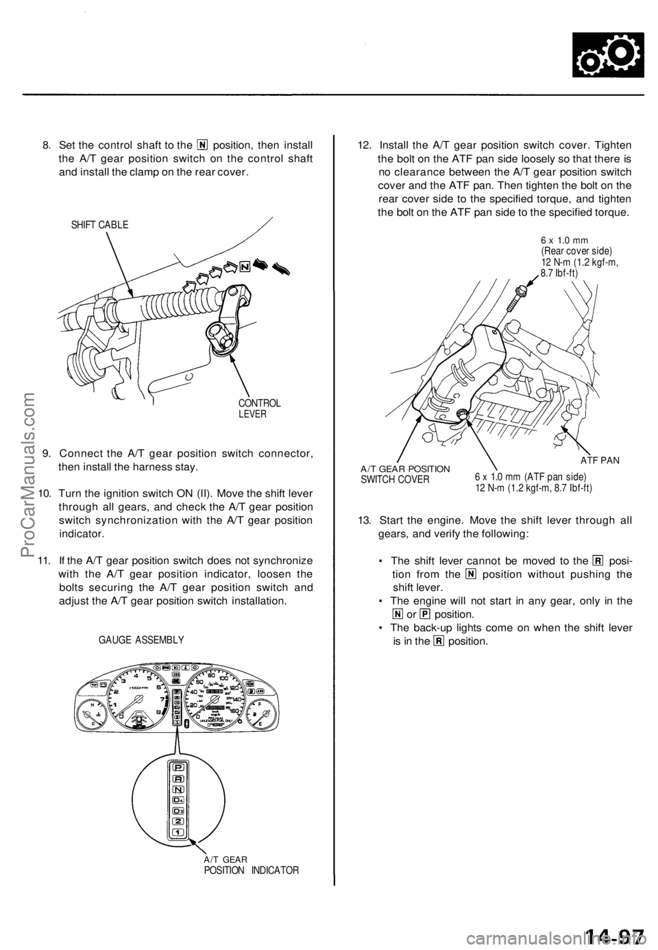
8.
Set the control shaft to the position, then install
the A/T gear position switch on the control shaft
and install the clamp on the rear cover.
SHIFT CABLE
CONTROL
LEVER
9. Connect the A/T gear position switch connector,
then install the harness stay.
10. Turn the ignition switch ON (II). Move the shift lever
through all gears, and check the A/T gear position
switch synchronization with the A/T gear position
indicator.
11. If the A/T gear position switch does not synchronize
with the A/T gear position indicator, loosen the
bolts securing the A/T gear position switch and
adjust the A/T gear position switch installation.
GAUGE ASSEMBLY
A/T GEAR
POSITION INDICATOR
12. Install the A/T gear position switch cover. Tighten
the bolt on the ATF pan side loosely so that there is
no clearance between the A/T gear position switch
cover and the ATF pan. Then tighten the bolt on the
rear cover side to the specified torque, and tighten
the bolt on the ATF pan side to the specified torque.
6 x 1.0 mm
(Rear cover side)
12 N-m (1.2 kgf-m,
8.7 Ibf-ft)
A/T GEAR POSITION
SWITCH COVER
ATF PAN
6 x 1.0 mm (ATF pan side)
12 N-m (1.2 kgf-m, 8.7 Ibf-ft)
13. Start the engine. Move the shift lever through all
gears, and verify the following:
• The shift lever cannot be moved to the posi-
tion from the position without pushing the
shift lever.
• The engine will not start in any gear, only in the
or position.
• The back-up lights come on when the shift lever
is in the position.ProCarManuals.com
Page 1084 of 1771
Transmission
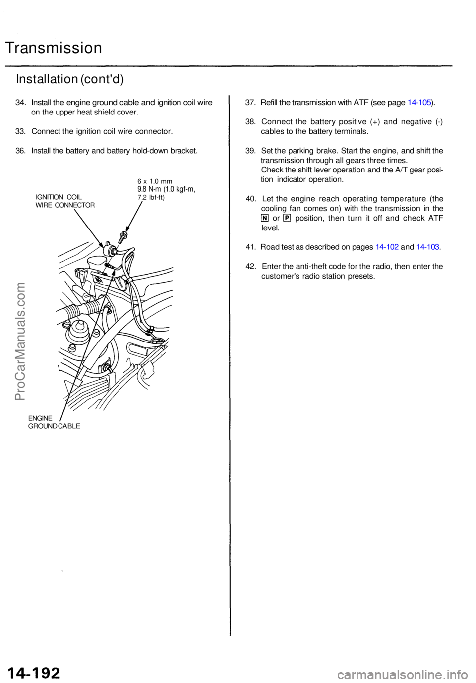
Installation (cont'd )
34. Instal l th e engin e groun d cabl e an d ignitio n coi l wir e
on th e uppe r hea t shiel d cover .
33 . Connec t th e ignitio n coi l wir e connector .
36 . Instal l th e batter y an d batter y hold-dow n bracket .
IGNITION COI LWIRE CONNECTO R
6 x 1. 0 m m9.8 N- m (1. 0 kgf-m ,7.2 Ibf-ft )
ENGIN EGROUN D CABL E
37. Refil l th e transmissio n wit h AT F (se e pag e 14-105 ).
38 . Connec t th e batter y positiv e (+ ) an d negativ e (- )
cable s t o th e batter y terminals .
39 . Se t th e parkin g brake . Star t th e engine , an d shif t th e
transmissio n throug h al l gear s thre e times .
Chec k th e shif t leve r operatio n an d th e A/ T gea r posi -
tio n indicato r operation .
40 . Le t th e engin e reac h operatin g temperatur e (th e
coolin g fa n come s on ) wit h th e transmissio n i n th e
or position , the n tur n i t of f an d chec k AT F
level .
41. Roa d tes t a s describe d o n page s 14-10 2 an d 14-103 .
42 . Ente r th e anti-thef t cod e fo r th e radio , the n ente r th e
customer' s radi o statio n presets .
ProCarManuals.com
Page 1177 of 1771
Steering Colum n
Installatio n
SRS component s ar e locate d i n thi s area . Revie w th e
SR S componen t locations , precautions , an d procedure s
i n th e SR S ( sectio n 24 ) befor e performin g repair s o r ser -
vice .
1.
2 .
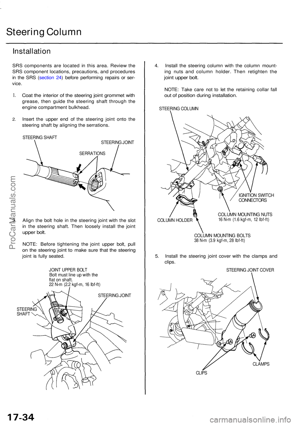
Coa t th e interio r o f th e steerin g join t gromme t wit h
grease , the n guid e th e steerin g shaf t throug h th e
engin e compartmen t bulkhead .
Inser t th e uppe r en d o f th e steerin g join t ont o th e
steerin g shaf t b y alignin g th e serrations .
STEERING SHAF TSTEERIN G JOIN T
SERRATION S
3. Alig n th e bol t hol e i n th e steerin g join t wit h th e slo t
i n th e steerin g shaft . The n loosel y instal l th e join t
uppe r bolt .
NOTE : Befor e tightenin g th e join t uppe r bolt , pul l
on th e steerin g join t t o mak e sur e tha t th e steerin g
joint i s full y seated .
JOINT UPPE R BOL TBolt mus t lin e u p wit h th eflat o n shaft .22 N- m (2. 2 kgf-m , 1 6 Ibf-ft )
STEERIN G JOIN T
STEERIN GSHAFT
4. Instal l th e steerin g colum n wit h th e colum n mount -
in g nut s an d colum n holder . The n retighte n th e
join t uppe r bolt .
NOTE : Tak e car e no t t o le t th e retainin g colla r fal l
out o f positio n durin g installation .
STEERING COLUM N
COLUMN HOLDE R
IGNITION SWITC HCONNECTOR S
COLUMN MOUNTIN G NUT S16 N- m (1. 6 kgf-m , 1 2 Ibf-ft )
COLUM N MOUNTIN G BOLT S38 N- m (3. 9 kgf-m , 2 8 Ibf-ft )
5. Instal l th e steerin g join t cove r wit h th e clamp s an d
clips .
STEERIN G JOIN T COVE R
CLAMP S
CLIPS
ProCarManuals.com
Page 1291 of 1771
Pump motor control:
The ABS control unit monitors the brake fluid pressure in the accumulator by the pressure switch ON/OFF signals. The
ABS control unit turns the pump on when the pressure in the accumulator drops, and stops the pump when the pressure
rises to the specified value.
If the pressure does not reach the specified value after the motor has operated continuously for a specified period, the
ABS control unit stops the motor and activates the ABS indicator light.
Self-diagnosis function:
The self-diagnosis function, provided in the sub-function of the ABS control unit, monitors the main system functions by
constantly transmitting the data between the two Central Processing Units (CPUs). When an abnormality is detected, the
ABS control unit turns the ABS indicator light on and stops the ABS, although the basic brake system continues to operate
normally.
When the ABS control unit detects an abnormality with the ABS and turns the ABS indicator light on, the diagnostic trou-
ble code (DTC), which shows the problem part or unit, is recorded in the control unit. The DTC can be read by the blinking
frequency of the ABS indicator light.
Fail-safe function:
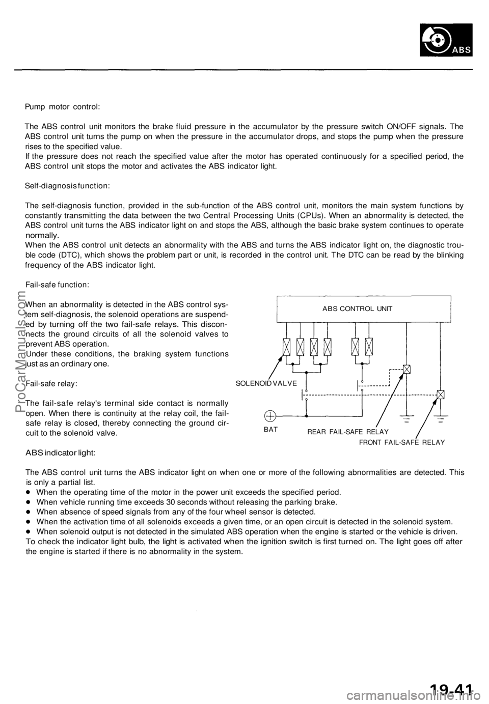
When an abnormality is detected in the ABS control sys-
tem self-diagnosis, the solenoid operations are suspend-
ed by turning off the two fail-safe relays. This discon-
nects the ground circuits of all the solenoid valves to
prevent ABS operation.
Under these conditions, the braking system functions
just as an ordinary one.
Fail-safe relay:
The fail-safe relay's terminal side contact is normally
open. When there is continuity at the relay coil, the fail-
safe relay is closed, thereby connecting the ground cir-
cuit to the solenoid valve.
ABS indicator light:
SOLENOID VALVE
BAT
REAR FAIL-SAFE RELAY
FRONT FAIL-SAFE RELAY
The ABS control unit turns the ABS indicator light on when one or more of the following abnormalities are detected. This
is only a partial list.
When the operating time of the motor in the power unit exceeds the specified period.
When vehicle running time exceeds 30 seconds without releasing the parking brake.
When absence of speed signals from any of the four wheel sensor is detected.
When the activation time of all solenoids exceeds a given time, or an open circuit is detected in the solenoid system.
When solenoid output is not detected in the simulated ABS operation when the engine is started or the vehicle is driven.
To check the indicator light bulb, the light is activated when the ignition switch is first turned on. The light goes off after
the engine is started if there is no abnormality in the system.
ABS CONTROL UNITProCarManuals.com