1995 ACURA TL ignition
[x] Cancel search: ignitionPage 235 of 1771
PGM-FI Main Relay
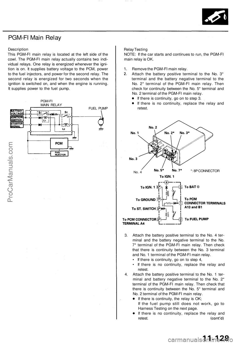
Description
This PGM-FI main relay is located at the left side of the
cowl. The PGM-FI main relay actually contains two indi-
vidual relays. One relay is energized whenever the igni-
tion is on. It supplies battery voltage to the PCM, power
to the fuel injectors, and power for the second relay. The
second relay is energized for two seconds when the
ignition is switched on, and when the engine is running.
It supplies power to the fuel pump.
PGM-FI
MAIN RELAY
FUEL PUMP
Relay Testing
NOTE: If the car starts and continues to run, the PGM-FI
main relay is OK.
Remove the PGM-FI main relay.
Attach the battery positive terminal to the No. 3*
terminal and the battery negative terminal to the
No. 2* terminal of the PGM-FI main relay. Then
check for continuity between the No. 5* terminal and
No. 2 terminal of the PGM-FI main relay.
If there is continuity, go on to step 3.
If there is no continuity, replace the relay and
retest.
No. 4
*: 8P CONNECTOR
3. Attach the battery positive terminal to the No. 4 ter-
minal and the battery negative terminal to the No.
7* terminal of the PGM-FI main relay. Then check
that there is continuity between the No. 3 terminal
and No. 1 terminal of the PGM-FI main relay.
• If there is continuity, go on to step 4,
• If there is no continuity, replace the relay and
retest.
4. Attach the battery positive terminal to the No. 1 ter-
minal and battery negative terminal to the No. 2*
terminal of the PGM-FI main relay. Then check that
there is continuity between the No. 5* terminal and
No. 2 terminal of the PGM-FI main relay.
If there is continuity, the relay is OK;
If the fuel pump still does not work, go to
Harness Testing on the next page.
If there is no continuity, replace the relay and
retest.ProCarManuals.com
Page 308 of 1771
PCM Reset Procedure
1. Make sure you have the anti-theft code for the radio, then write down the frequencies for the radio's preset buttons.
2. Turn the ignition switch OFF.
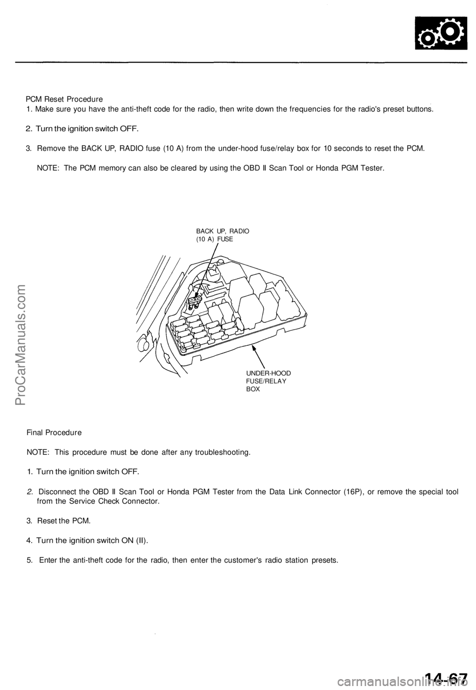
3. Remove the BACK UP, RADIO fuse (10 A) from the under-hood fuse/relay box for 10 seconds to reset the PCM.
NOTE: The PCM memory can also be cleared by using the OBD II Scan Tool or Honda PGM Tester.
BACK UP, RADIO
(10 A) FUSE
UNDER-HOOD
FUSE/RELAY
BOX
Final Procedure
NOTE: This procedure must be done after any troubleshooting.
1. Turn the ignition switch OFF.
2. Disconnect the OBD II Scan Tool or Honda PGM Tester from the Data Link Connector (16P), or remove the special tool
from the Service Check Connector.
3. Reset the PCM.
4. Turn the ignition switch ON (II).
5. Enter the anti-theft code for the radio, then enter the customer's radio station presets.ProCarManuals.com
Page 319 of 1771
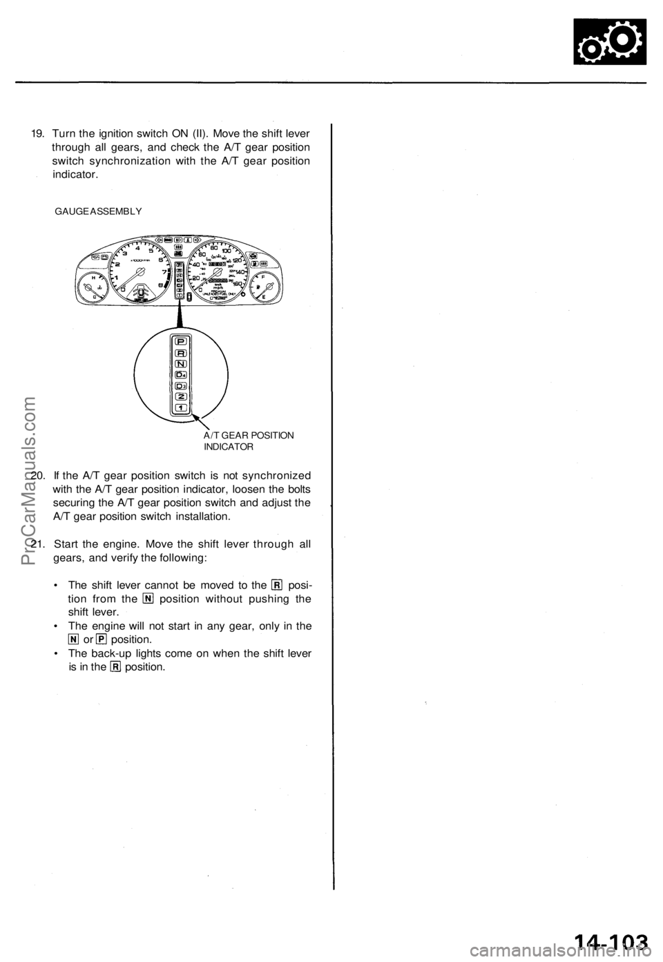
19. Turn the ignition switch ON (II). Move the shift lever
through all gears, and check the A/T gear position
switch synchronization with the A/T gear position
indicator.
GAUGE ASSEMBLY
20. If the A/T gear position switch is not synchronized
with the A/T gear position indicator, loosen the bolts
securing the A/T gear position switch and adjust the
A/T gear position switch installation.
21. Start the engine. Move the shift lever through all
gears, and verify the following:
• The shift lever cannot be moved to the posi-
tion from the position without pushing the
shift lever.
• The engine will not start in any gear, only in the
or position.
• The back-up lights come on when the shift lever
is in the position.
A/T GEAR POSITION
INDICATORProCarManuals.com
Page 511 of 1771
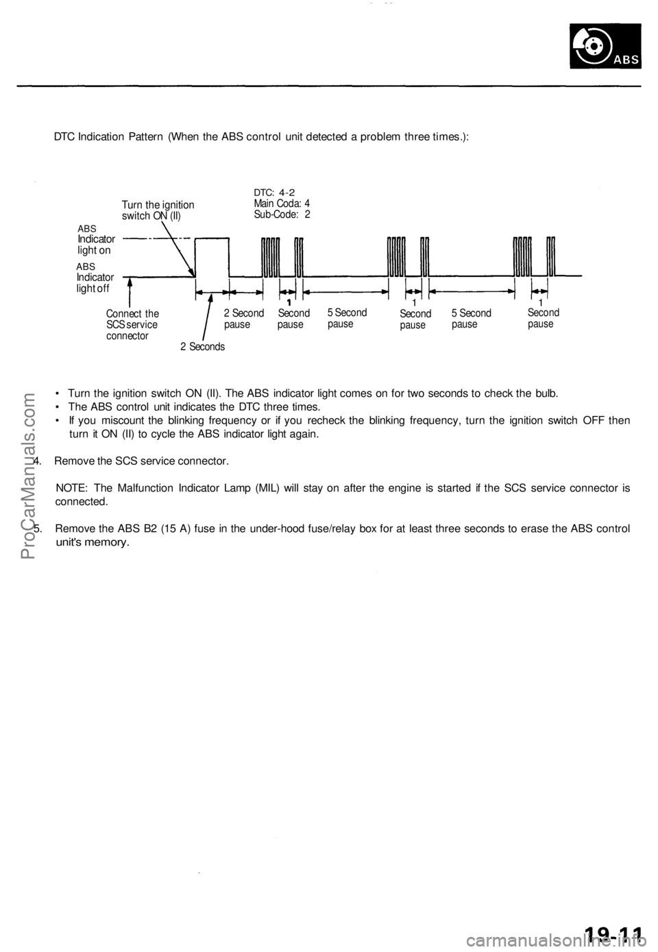
DTC Indication Pattern (When the ABS control unit detected a problem three times.):
Turn the ignition
switch ON (II)
ABS
Indicator
light on
ABS
Indicator
light off
DTC:
4-2
Main Coda: 4
Sub-Code: 2
Connect the
SCS service
connector
2 Second Second
pause pause
5 Second
pause
1
Second
pause
5 Second
pause
1
Second
pause
2 Seconds
• Turn the ignition switch ON (II). The ABS indicator light comes on for two seconds to check the bulb.
• The ABS control unit indicates the DTC three times.
• If you miscount the blinking frequency or if you recheck the blinking frequency, turn the ignition switch OFF then
turn it ON (II) to cycle the ABS indicator light again.
4. Remove the SCS service connector.
NOTE: The Malfunction Indicator Lamp (MIL) will stay on after the engine is started if the SCS service connector is
connected.
5. Remove the ABS B2 (15 A) fuse in the under-hood fuse/relay box for at least three seconds to erase the ABS control
unit's memory.ProCarManuals.com
Page 522 of 1771
Troubleshooting Precautions
ABS Indicator Light
1. If the system is OK, the ABS indicator light goes off two seconds after turning the ignition switch ON (II) without start-
ing the engine. After starting the engine, the ABS indicator light comes on again and goes off after two seconds. This
occurs because the ABS control unit is activated by the IG2 power source.
2. The ABS indicator light comes on when the ABS control unit detects a problem in the system. However, even though
the system is normal, the ABS indicator light comes on, too, under the following conditions. To determine the actual
cause of problem, question the customer about the problem, talking the following conditions into consideration.
Only drive wheels rotate
One wheel stuck of drive wheels
Vehicle spin
ABS operate condition continue for long time
Signal disturbance
3. When a problem is detected and the ABS indicator light comes on, there are cases when the indicator light stays on
until the ignition switch is turned OFF, and cases when the indicator light goes off automatically when the system
returns normal. For the DTC 61 and 62, the indicator light goes off automatically when the system returns normal. For
all other codes, the indicator light stays on until the ignition switch is turned OFF.
4. For DTCs 12, 14, 16, 18, 21, 22, 23, 24, 51, 52 and 53, the indicator light goes off when the vehicle is driven again and
the signals are OK after the ignition switch is turned from OFF to ON (II). However, if the DTC is erased, the CPU is
reset and the indicator light goes off right after the engine is started if the signals are OK.
Diagnostic Trouble Code (DTC)
1. The DTC is not memorized if the CPU cannot be activated or the CPU fails and the indicator light comes on.
2. The memory can hold any number of DTCs. However, when the same DTC is detected more than once, the later one
is written over the old one. Therefore, when the same problem is detected repeatedly, it is memorized as one DTC.
3. The DTCs are indicated in the order of ascending number, not in the order they occur.
4. The DTCs are memorized in the EEPROM (non-volatile memory). Therefore, the memorized DTCs cannot be canceled
by disconnecting the battery. Perform the specified procedures to erase the DTCs.
Self-diagnosis
1. The
self-diagnosis
can be
classified
into
two
categories.
• Initial diagnosis: Performed right after the engine starts and until the ABS indicator light goes off.
• Regular diagnosis: Performed right after the initial diagnosis until the ignition switch is turned OFF.
2. When a problem is detected by self-diagnosis, the system
• Turns the ABS indicator light ON
• Memorizes the DTC
• Turns the fail-safe relay OFF
• Stops ABS controlProCarManuals.com
Page 537 of 1771
Diagnostic Trouble Code (DTC)
DTC Erasure
1. Pull the parking brake lever up.
2. Push and hold the TCS switch, then turn the ignition switch ON (II).
3. Hold the TCS switch pushed for four seconds (do not release the TCS switch), then release the TCS switch for less than
six seconds.
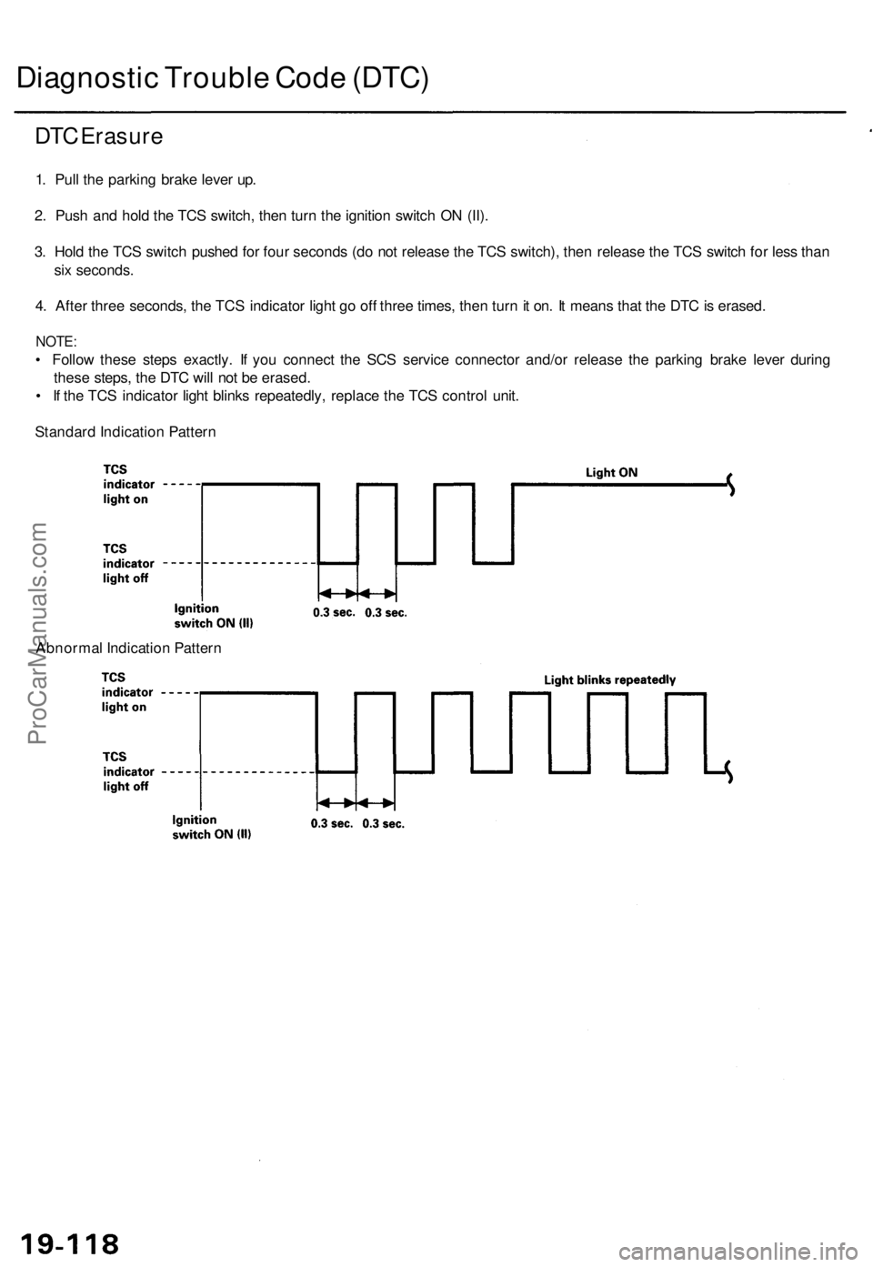
4. After three seconds, the TCS indicator light go off three times, then turn it on. It means that the DTC is erased.
NOTE:
• Follow these steps exactly. If you connect the SCS service connector and/or release the parking brake lever during
these steps, the DTC will not be erased.
• If the TCS indicator light blinks repeatedly, replace the TCS control unit.
Standard Indication Pattern
Abnormal Indication PatternProCarManuals.com
Page 562 of 1771
Troubleshooting
Radiator Fan Control Module Input Tests
NOTE: Perform the following tests with the radiator fan control module 8P connector connected, the ignition switch ON (II),
and the A/C switch OFF. If you find the cause of a problem, correct it before you continue.
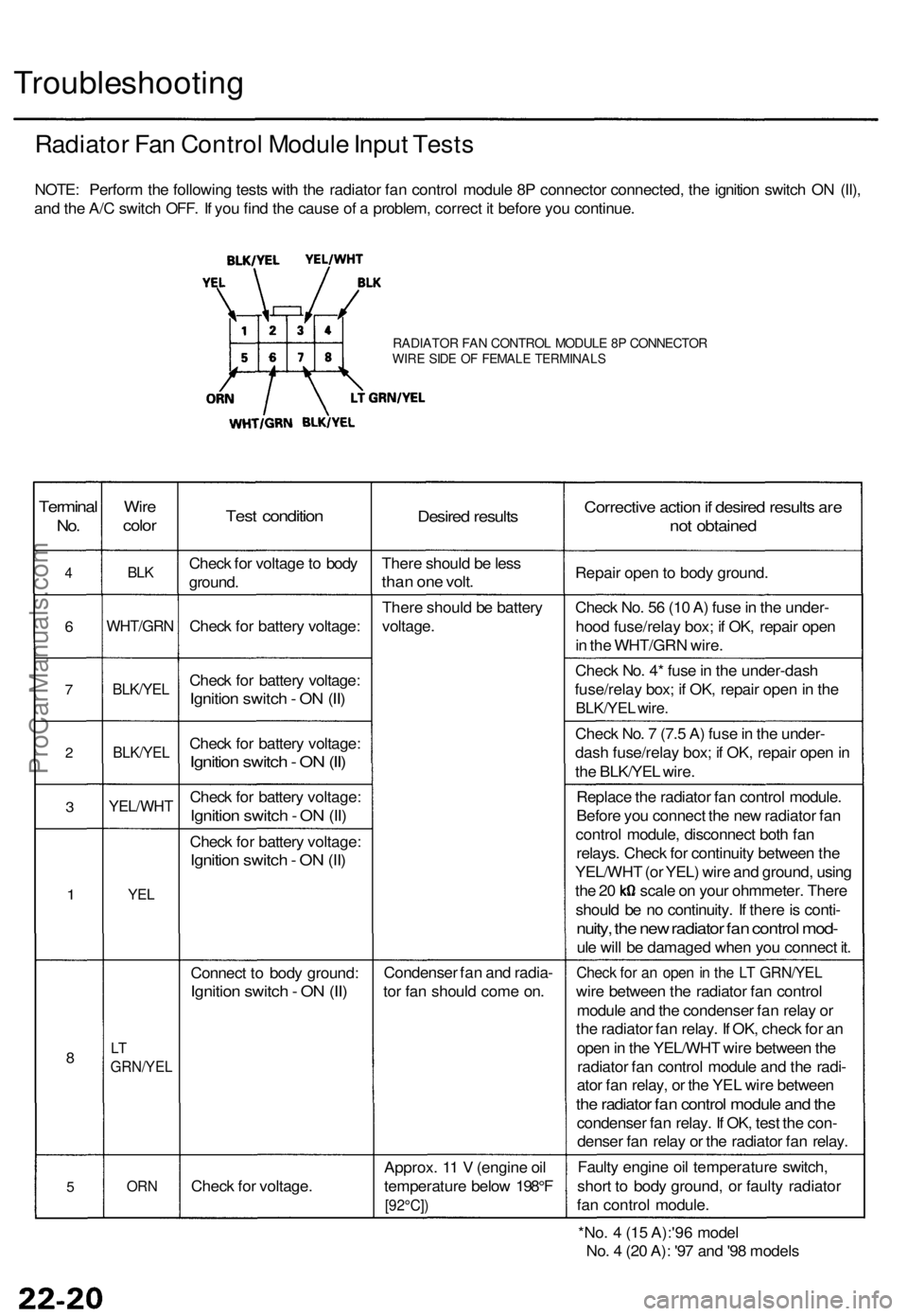
RADIATOR FAN CONTROL MODULE 8P CONNECTOR
WIRE SIDE OF FEMALE TERMINALS
Terminal
No.
4
6
7
2
3
1
8
5
Wire
color
BLK
WHT/GRN
BLK/YEL
BLK/YEL
YEL/WHT
YEL
LT
GRN/YEL
ORN
Test condition
Check for voltage to body
ground.
Check for battery voltage:
Check for battery voltage:
Ignition switch - ON (II)
Check for battery voltage:
Ignition switch - ON (II)
Check for battery voltage:
Ignition switch - ON (II)
Check for battery voltage:
Ignition switch - ON (II)
Connect to body ground:
Ignition switch - ON (II)
Check for voltage.
Desired results
There should be less
than one volt.
There should be battery
voltage.
Condenser fan and radia-
tor fan should come on.
Approx. 11 V (engine oil
temperature below 198°F
[92°C])
Corrective action if desired results are
not obtained
Repair open to body ground.
Check No. 56 (10 A) fuse in the under-
hood fuse/relay box; if OK, repair open
in the WHT/GRN wire.
Check No. 4* fuse in the under-dash
fuse/relay box; if OK, repair open in the
BLK/YEL wire.
Check No. 7 (7.5 A) fuse in the under-
dash fuse/relay box; if OK, repair open in
the BLK/YEL wire.
Replace the radiator fan control module.
Before you connect the new radiator fan
control module, disconnect both fan
relays. Check for continuity between the
YEL/WHT (or YEL) wire and ground, using
the 20 scale on your ohmmeter. There
should be no continuity. If there is conti-
nuity, the new radiator fan control mod-
ule will be damaged when you connect it.
Check for an open in the LT GRN/YEL
wire between the radiator fan control
module and the condenser fan relay or
the radiator fan relay. If OK, check for an
open in the YEL/WHT wire between the
radiator fan control module and the radi-
ator fan relay, or the YEL wire between
the radiator fan control module and the
condenser fan relay. If OK, test the con-
denser fan relay or the radiator fan relay.
Faulty engine oil temperature switch,
short to body ground, or faulty radiator
fan control module.
*No. 4 (15 A):'96 model
No. 4 (20 A): '97 and '98 modelsProCarManuals.com
Page 585 of 1771
Check for Wear and Damage
The starter should crank the engine smoothly and steadily.
If the starter engages, but cranks the engine erratically,
remove it, and inspect the starter drive gear and torque
converter ring gear for damage.
• Check the drive gear overrunning clutch for binding
or slipping when the armature is rotated with the
drive gear held. If the clutch is damaged, replace the
clutch assembly.
Check Cranking Voltage and Current Draw
Cranking voltage should be no less than 8.0 volts.
Current draw should be no more than 450 amperes.
If cranking voltage is too low, or current draw too high,
check for:
Dead or low battery
Open circuit in starter armature commutator segments
Starter armature dragging
Shorted armature winding
Excessive drag in engine
Check Cranking rpm
Engine speed during cranking should be above 100 rpm.
If speed is too low, check for:
Loose battery or starter terminals
Excessively worn starter brushes
Open circuit in commutator segments
Dirty or damaged helical spline or drive gear
Defective drive gear overrunning clutch
Check Starter Disengagement
With the shift lever in or , turn the ignition switch to
"START (III)", and release to "ON (II)". The starter drive
gear should disengage from the flywheel ring gear when
you release the key.
If the drive gear hangs upon the flywheel ring gear, check
for:
• Solenoid plunger and switch malfunction
• Dirty drive gear assembly or damaged overrunning
clutchProCarManuals.com