1995 ACURA TL ignition
[x] Cancel search: ignitionPage 45 of 1771
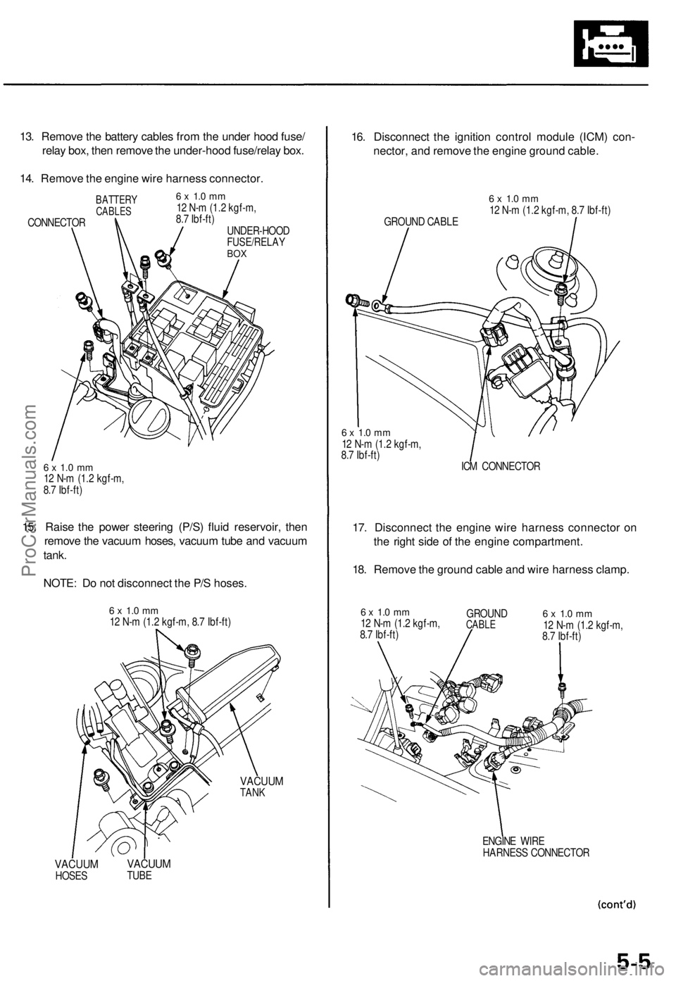
13. Remove the battery cables from the under hood fuse/
relay box, then remove the under-hood fuse/relay box.
14. Remove the engine wire harness connector.
BATTERY
CABLES
CONNECTOR
6 x 1.0 mm
12 N-m (1.2 kgf-m,
8.7 Ibf-ft)
UNDER-HOOD
FUSE/RELAY
BOX
6 x 1.0 mm
12 N-m (1.2 kgf-m,
8.7 Ibf-ft)
15. Raise the power steering (P/S) fluid reservoir, then
remove the vacuum hoses, vacuum tube and vacuum
tank.
NOTE: Do not disconnect the P/S hoses.
6 x 1.0 mm
12 N-m (1.2 kgf-m, 8.7 Ibf-ft)
VACUUM
TANK
VACUUM
HOSES
VACUUM
TUBE
16. Disconnect the ignition control module (ICM) con-
nector, and remove the engine ground cable.
GROUND CABLE
6 x 1.0 mm
12 N-m (1.2 kgf-m, 8.7 Ibf-ft)
6 x 1.0 mm
12 N-m (1.2 kgf-m,
8.7 Ibf-ft)
ICM CONNECTOR
17. Disconnect the engine wire harness connector on
the right side of the engine compartment.
18. Remove the ground cable and wire harness clamp.
6 x 1.0 mm
12 N-m (1.2 kgf-m,
8.7 Ibf-ft)
GROUND
CABLE
6 x 1.0 mm
12 N-m (1.2 kgf-m,
8.7 Ibf-ft)
ENGINE WIRE
HARNESS CONNECTORProCarManuals.com
Page 75 of 1771

22. Remove the positive crankcase ventilation (PCV)
hose.
23. Remove the bolt securing the automatic transmis-
sion fluid (ATF) dipstick tube bracket.
6 x 1.0 mm
12 N-m (1.2 kgf-m,
8.7 Ibf-ft)
ATF BRACKET
DIPSTICK TUBE
BRACKET
PCV HOSE
24.
Remove the engine wire harness connectors and
wire harness clamps from the cylinder heads and
intake manifold.
Six injector connectors
Six ignition coil connectors
Throttle position sensor connector
CKP/CYP sensor connector
Intake air temperature (IAT) sensor connector
Exhaust gas recirculation (EGR) valve lift sensor
connector
Idle air control (IAC) valve connector
Engine coolant temperature (ECT) sensor con-
nector
ECT gauge sending unit connector
Engine oil temperature sensor connector
Left primary heated oxygen sensor (left primary
HO2S) connector
Right primary heated oxygen sensor (right pri-
mary HO2S) connector
Evaporative emission (EVAP) purge control
solenoid valve connector ('97 - '98)
25. Remove the inlet pipe mounting bolts from the right
cylinder head cover.
26. Remove the vacuum hoses and breather hose.
6 x 1.0 mm
12 N-m (1.2 kgf-m, 8.7 Ibf-ft)
BREATHER
HOSE
VACUUM
HOSES
27. Remove the six ignition coils from the left and right
cylinder head covers.
6 x 1.0 mm
12 N-m (1.2 kgf-m, 8.7 Ibf-ft)
IGNITION
COILProCarManuals.com
Page 144 of 1771
Engine Coolan t Refillin g an d Bleedin g
CAUTION : Whe n pourin g engin e coolant , b e sur e t o
shu t th e rela y bo x li d an d no t t o le t coolan t spil l o n th e
electrica l part s o r th e paint . I f an y coolan t spills , rins e it
of f immediately .
NOTE:
Perfor m thi s procedur e whe n th e engin e is cool .
Befor e replacin g th e coolant , tur n th e ignitio n O N (II) ,
slowl y tur n th e climat e contro l temperatur e kno b t o
90 ° an d tur n of f th e ignition . Thi s wil l allo w th e
coolan t i n th e heate r t o drai n ou t wit h th e res t o f th e
system .
1 . Mak e sur e yo u hav e th e anti-thef t cod e fo r th e radio ,
the n writ e dow n th e frequencie s fo r th e radio' s pre -
se t buttons .
2 . Disconnec t th e batter y negativ e termina l first , the n
th e positiv e terminal , the n remov e th e batter y an d
batter y bas e (se e pag e 5-4 ).
3 . Whe n th e radiato r i s cool , remov e th e radiato r cap .
Loose n th e drai n plug , an d drai n th e coolant .
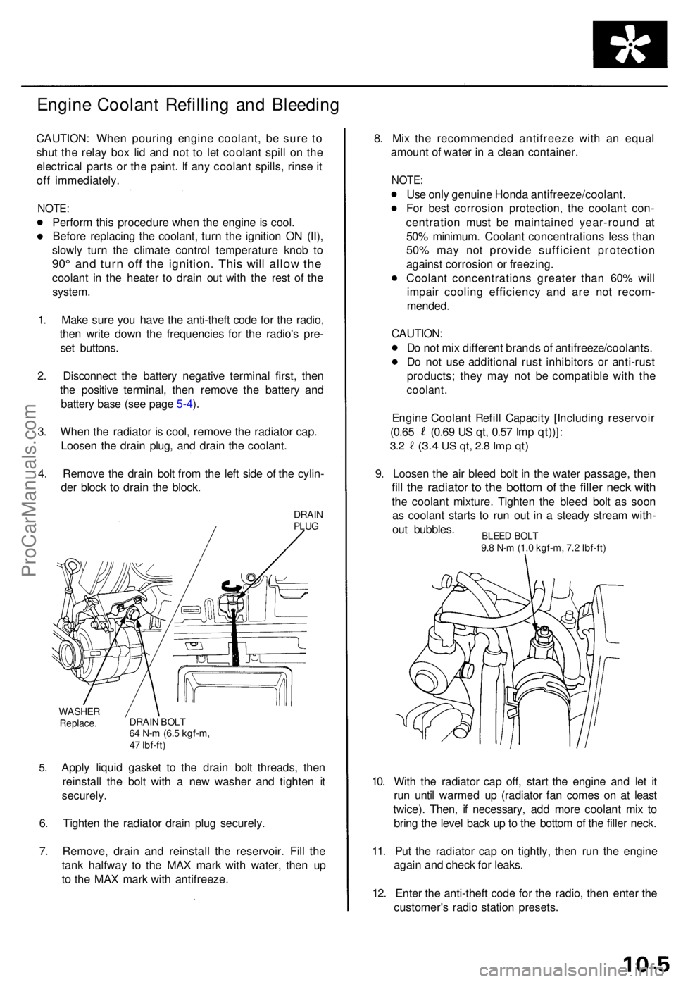
4 . Remov e th e drai n bol t fro m th e lef t sid e o f th e cylin -
de r bloc k t o drai n th e block .
DRAINPLUG
5.
WASHE RReplace .DRAIN BOL T64 N- m (6. 5 kgf-m ,
4 7 Ibf-ft )
Apply liqui d gaske t t o th e drai n bol t threads , the n
reinstal l th e bol t wit h a ne w washe r an d tighte n i t
securely .
6. Tighte n th e radiato r drai n plu g securely .
7 . Remove , drai n an d reinstal l th e reservoir . Fil l th e
tan k halfwa y t o th e MA X mar k wit h water , the n u p
t o th e MA X mar k wit h antifreeze . 8
. Mi x th e recommende d antifreez e wit h a n equa l
amoun t o f wate r i n a clea n container .
NOTE:
Use onl y genuin e Hond a antifreeze/coolant .
Fo r bes t corrosio n protection , th e coolan t con -
centratio n mus t b e maintaine d year-roun d a t
50 % minimum . Coolan t concentration s les s tha n
50 % ma y no t provid e sufficien t protectio n
agains t corrosio n o r freezing .
Coolan t concentration s greate r tha n 60 % wil l
impai r coolin g efficienc y an d ar e no t recom -
mended .
CAUTION :
D o no t mi x differen t brand s o f antifreeze/coolants .
D o no t us e additiona l rus t inhibitor s o r anti-rus t
products ; the y ma y no t b e compatibl e wit h th e
coolant .
Engine Coolan t Refil l Capacit y [Includin g reservoi r
(0.65 (0.6 9 U S qt , 0.5 7 Im p qt))] :
3.2 (3. 4 US qt , 2. 8 Im p qt )
9. Loose n th e ai r blee d bol t i n th e wate r passage , the n
fill th e radiato r t o th e botto m o f th e fille r nec k wit h
the coolan t mixture . Tighte n th e blee d bol t a s soo n
a s coolan t start s t o ru n ou t i n a stead y strea m with -
ou t bubbles .
10 . Wit h th e radiato r ca p off , star t th e engin e an d le t i t
ru n unti l warme d u p (radiato r fa n come s o n a t leas t
twice) . Then , i f necessary , ad d mor e coolan t mi x t o
brin g th e leve l bac k u p to th e botto m o f th e fille r neck .
11 . Pu t th e radiato r cap on tightly , the n ru n th e engin e
agai n an d chec k fo r leaks .
12 . Ente r th e anti-thef t cod e fo r th e radio , the n ente r th e
customer' s radi o statio n presets .
BLEED BOL T9.8 N- m (1. 0 kgf-m , 7. 2 Ibf-ft )
ProCarManuals.com
Page 181 of 1771
II. Powertrain Control Module (PCM) Reset Procedure
Either of the following actions will reset the PCM
Use the OBD II scan tool or Honda PGM Tester to clear the PCM's memory.
NOTE: See the OBD II scan tool or Honda PGM Tester user's manuals for specific operating instructions.
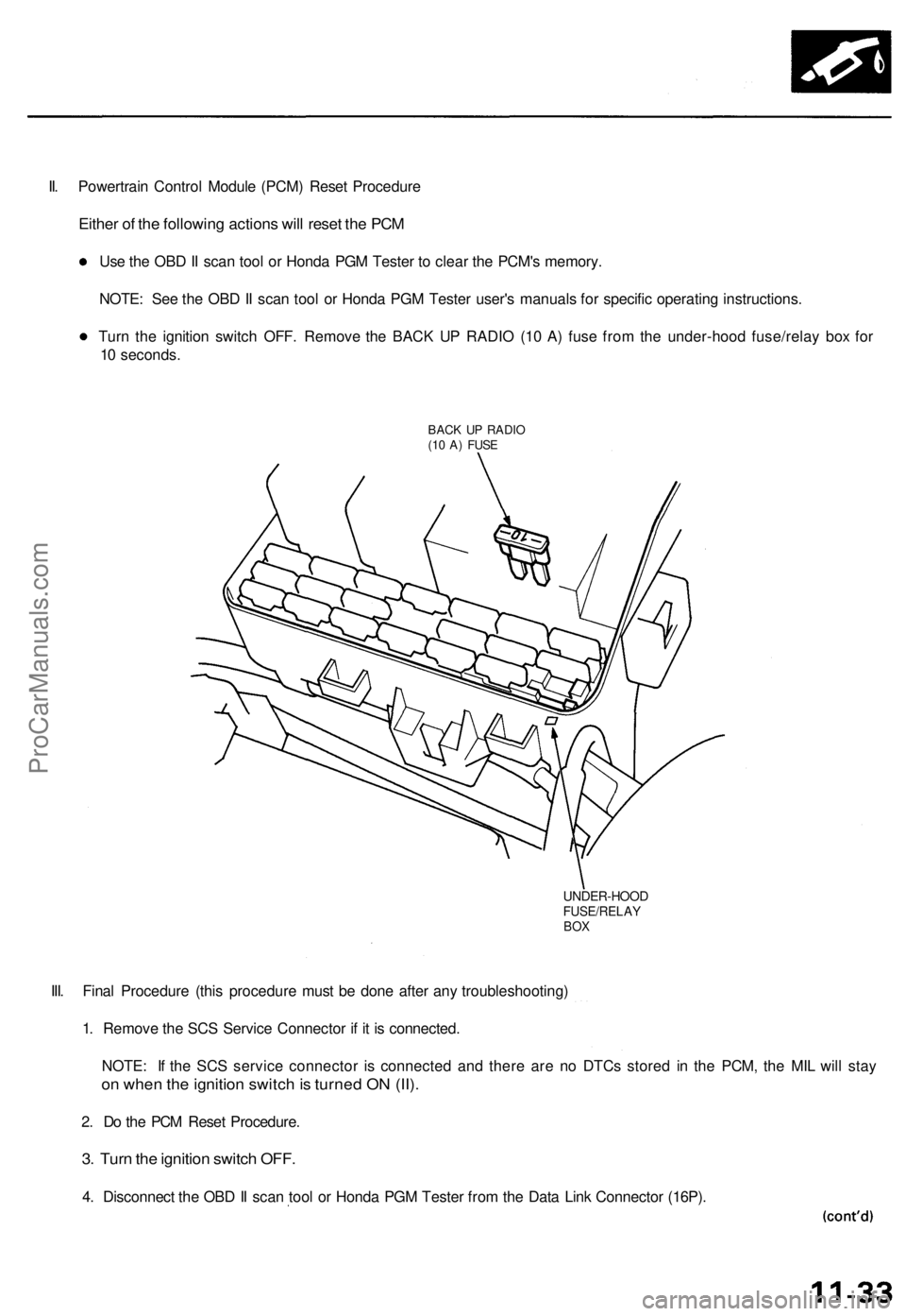
Turn the ignition switch OFF. Remove the BACK UP RADIO (10 A) fuse from the under-hood fuse/relay box for
10 seconds.
BACK UP RADIO
(10 A) FUSE
UNDER-HOOD
FUSE/RELAY
BOX
III. Final Procedure (this procedure must be done after any troubleshooting)
1. Remove the SCS Service Connector if it is connected.
NOTE: If the SCS service connector is connected and there are no DTCs stored in the PCM, the MIL will stay
on when the ignition switch is turned ON (II).
2. Do the PCM Reset Procedure.
3. Turn the ignition switch OFF.
4. Disconnect the OBD II scan tool or Honda PGM Tester from the Data Link Connector (16P).ProCarManuals.com
Page 200 of 1771
PGM-FI System
System Description (cont'd)
3. Fuel Cut-off Control
During deceleration with the throttle valve closed, current to the fuel injectors is cut off to improve fuel economy at
speeds over 1,000 rpm.
Fuel cut-off action also takes place when engine speed exceeds 6,500 rpm, regardless of the position of the throttle
valve, to protect the engine from over-revving.
4. A/C Compressor Clutch Relay .
When the PCM receives a demand for cooling from the air conditioning system, it delays the compressor from being
energized, and enriches the mixture to assure a smooth transition to the A/C mode.
5. Evaporative Emission (EVAP) Purge Control Solenoid Valve
'96 model: When the engine coolant temperature is below 158°F (70°C), the PCM controls the EVAP purge control
solenoid valve which cuts vacuum to the EVAP purge control canister diaphragm.
'97 - 98 models: When the engine coolant temperature is above 99°F (37°C), the PCM controls the EVAP purge control
solenoid valve which controls vacuum to the EVAP purge control canister.
6. Intake Air Bypass (IAB) Low Control Solenoid Valve, Intake Air Bypass (IAB) High Control Solenoid Valve
When engine speed is below 3,350 rpm, the IAB High Control Solenoid Valve and IAB Low Control Solenoid Valve are
activated by a signal from the PCM. Intake air flows through a long chamber path, increasing torque at low RPM.
When engine speed is 3,350 - 3,950 rpm, the IAB Low Control Solenoid Valve is deactivated by the PCM. Intake air
flows through a short chamber path, increasing mid-range torque.
When the engine rpm is above 3,950 rpm, the IAB Low Control Solenoid Valve and IAB High Control Solenoid Valve are
deactivated by the PCM. This creates a very short intake path and increases high-speed torque.
7. Exhaust Gas Recirculation (EGR) Control Solenoid Valve
When the EGR is required for control of oxides of nitrogen (NOx) emissions, the PCM controls the EGR control solenoid
valve which supplies regulated vacuum to the EGR valve.
ECM Fail-safe/Back-up Functions
1. Fail-safe Function
When an abnormality occurs in a signal from a sensor, the PCM ignores that signal and assumes a pre-programmed
value for that sensor that allows the engine to continue to run.
2. Back-up Function
When an abnormality occurs in the PCM itself, the fuel injectors are controlled by a back-up circuit independent of the
system in order to permit minimal driving.
3. Self-diagnosis Function [Malfunction Indicator Lamp (MIL)]
When an abnormality occurs in a signal from a sensor, the PCM supplies ground for the MIL and stores the DTC in
erasable memory. When the ignition is initially turned on, the PCM supplies ground for the MIL for two seconds to
check the MIL bulb condition.
4. Two Driving Cycle Detection Method
To prevent false indications, the two driving cycle detection method is used for the H02S, fuel metering-related, idle
control system, ECT sensor, EGR system, TWC, EVAP control system and other self-diagnostic functions. When an
abnormality occurs, the PCM stores it in its memory. When the same abnormality recurs after the ignition switch is
turned OFF and ON (II) again, the PCM informs the driver by lighting the MIL.
However, to ease troubleshooting, this function is cancelled when you short the service check connector. The MIL will
then blink immediately when an abnormality occurs.ProCarManuals.com
Page 201 of 1771
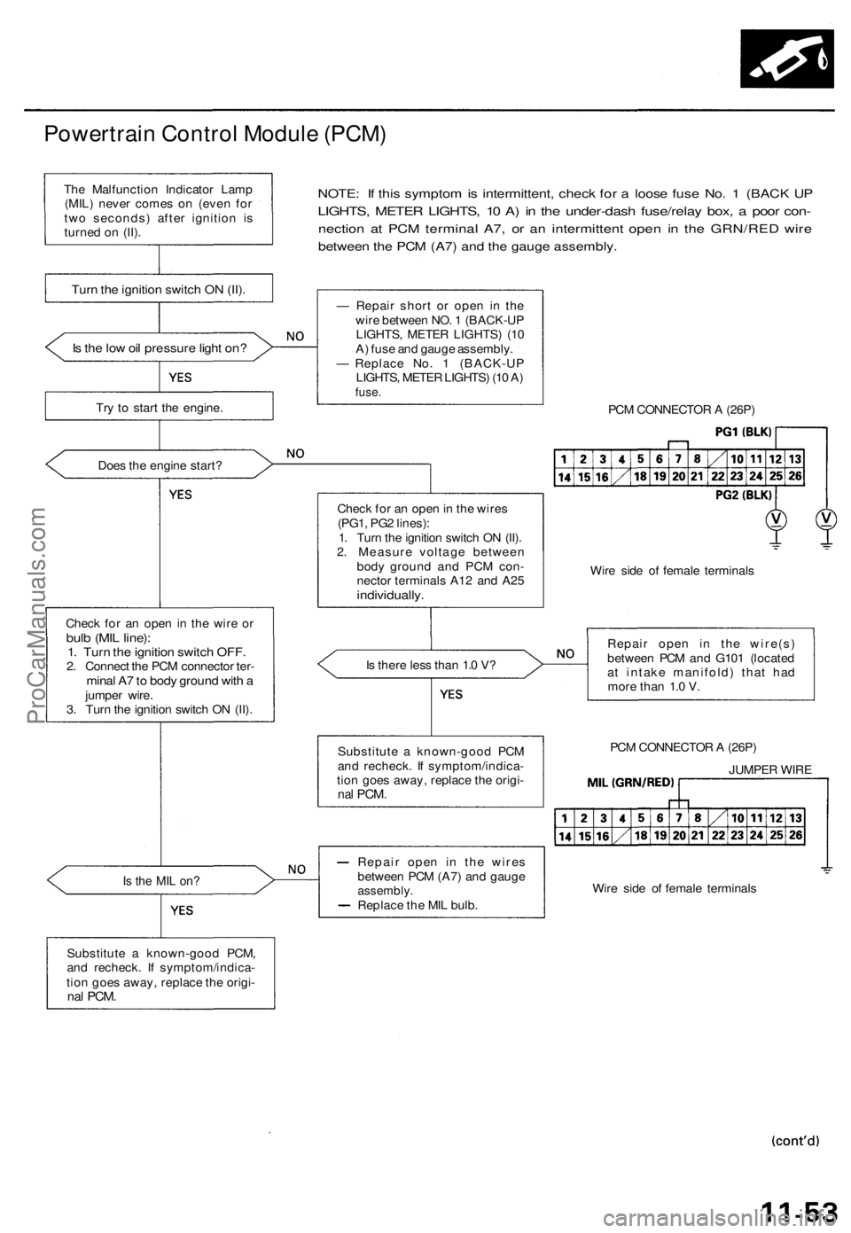
Powertrain Control Module (PCM)
NOTE: If this symptom is intermittent, check for a loose fuse No. 1 (BACK UP
LIGHTS, METER LIGHTS, 10 A) in the under-dash fuse/relay box, a poor con-
nection at PCM terminal A7, or an intermittent open in the GRN/RED wire
between the PCM (A7) and the gauge assembly.
Is the low oil pressure light on?
Try to start the engine.
Does the engine start?
Check for an open in the wire or
bulb (MIL line):
1. Turn the ignition switch OFF.
2. Connect the PCM connector ter-
minal A7 to body ground with a
jumper wire.
3. Turn the ignition switch ON (II).
Is the MIL on?
Substitute a known-good PCM,
and recheck. If symptom/indica-
tion goes away, replace the origi-
nal
PCM.
— Repair short or open in the
wire between NO. 1 (BACK-UP
LIGHTS, METER LIGHTS) (10
A) fuse and gauge assembly.
— Replace No. 1 (BACK-UP
LIGHTS, METER LIGHTS) (10 A)
fuse.
PCM CONNECTOR A (26P)
Check for an open in the wires
(PG1, PG2 lines):
1. Turn the ignition switch ON (II).
2. Measure voltage between
body ground and PCM con-
nector terminals A12 and A25
individually.
Wire side of female terminals
Is there less than 1.0 V?
Repair open in the wire(s)
between PCM and G101 (located
at intake manifold) that had
more than 1.0 V.
PCM CONNECTOR A (26P)
JUMPER WIRE
Wire side of female terminals
Repair open in the wires
between PCM (A7) and gauge
assembly.
Replace the MIL bulb.
Substitute a known-good PCM
and recheck. If symptom/indica-
tion goes away, replace the origi-
nal
PCM.
Turn the ignition switch ON (II).
The Malfunction Indicator Lamp
(MIL) never comes on (even for
two seconds) after ignition is
turned on (II).ProCarManuals.com
Page 210 of 1771
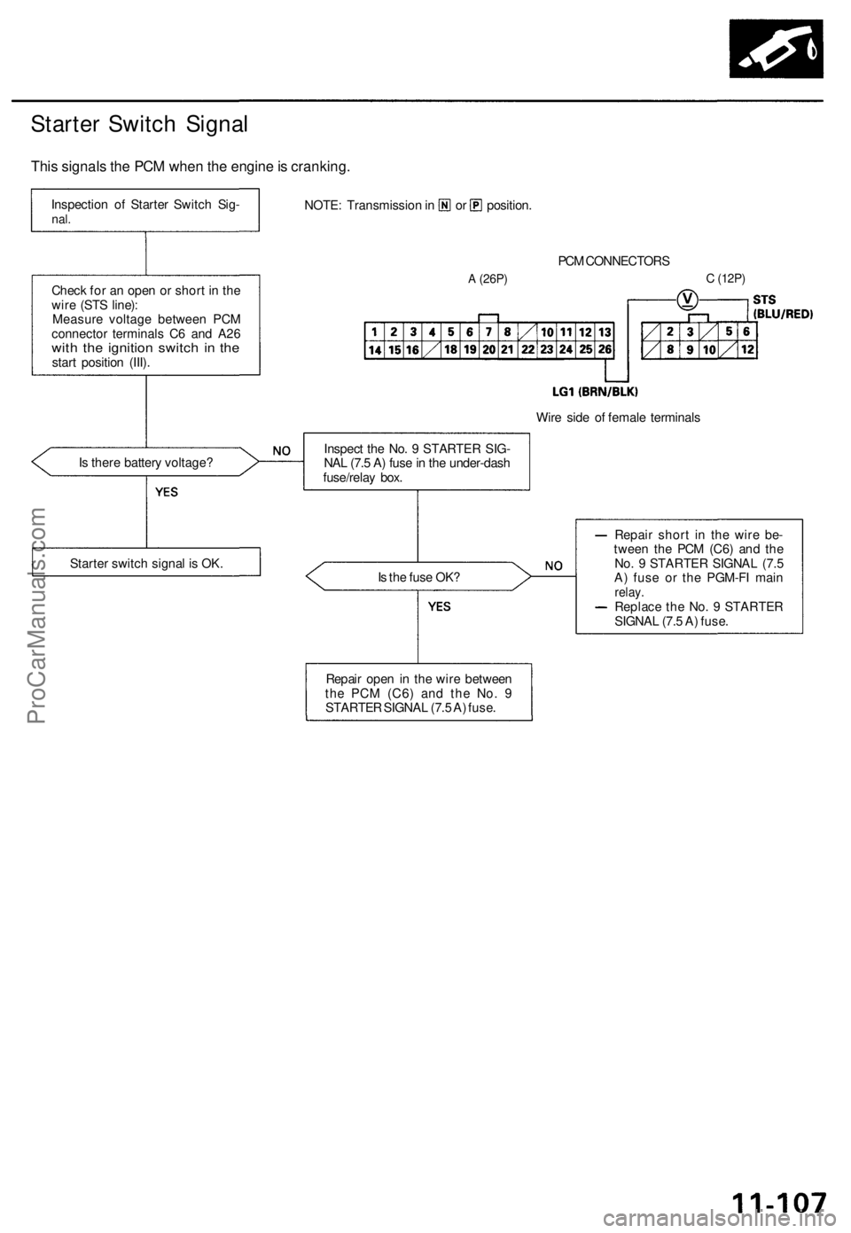
Starter Switch Signal
This signals the PCM when the engine is cranking.
PCM CONNECTORS
A
(26P)
C
(12P)
Wire side of female terminals
Is there battery voltage?
Is the fuse OK?
Repair short in the wire be-
tween the PCM (C6) and the
No. 9 STARTER SIGNAL (7.5
A) fuse or the PGM-FI main
relay.
Replace the No. 9 STARTER
SIGNAL (7.5 A) fuse.
Repair open in the wire between
the PCM
(C6)
and the No. 9
STARTER SIGNAL (7.5 A) fuse.
Starter switch signal is OK.
Inspect the No. 9 STARTER SIG-
NAL (7.5 A) fuse in the under-dash
fuse/relay box.
Check for an open or short in the
wire (STS line):
Measure voltage between PCM
connector terminals C6 and A26
with the ignition switch in the
start position (III).
Inspection of Starter Switch Sig-
nal.
NOTE: Transmission in or position.ProCarManuals.com
Page 227 of 1771
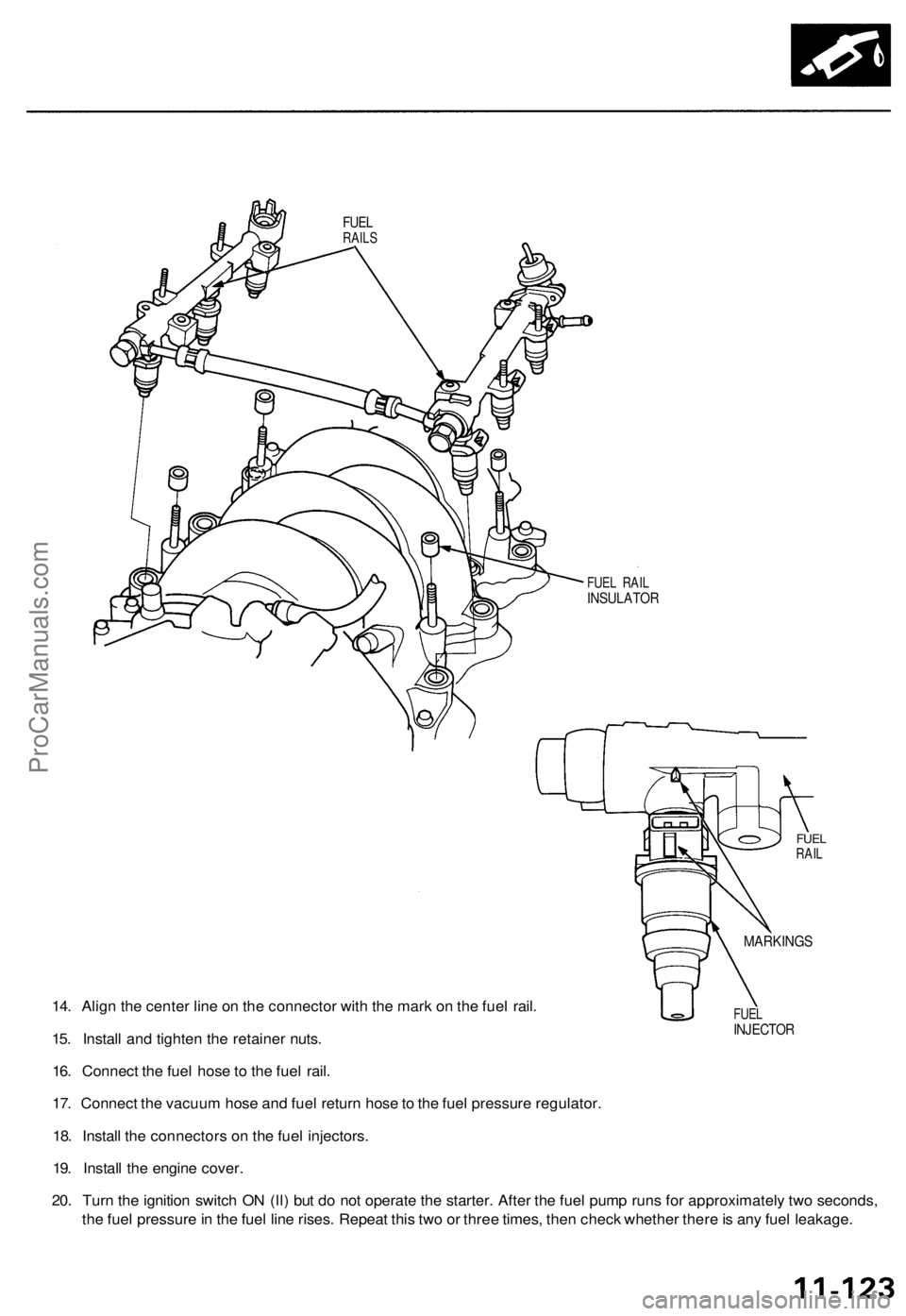
14. Align the center line on the connector with the mark on the fuel rail.
15. Install and tighten the retainer nuts.
16. Connect the fuel hose to the fuel rail.
17. Connect the vacuum hose and fuel return hose to the fuel pressure regulator.
18. Install the connectors on the fuel injectors.
19. Install the engine cover.
20. Turn the ignition switch ON (ll) but do not operate the starter. After the fuel pump runs for approximately two seconds,
the fuel pressure in the fuel line rises. Repeat this two or three times, then check whether there is any fuel leakage.
FUEL
INJECTOR
MARKINGS
FUEL
RAIL
FUEL RAIL
INSULATOR
FUEL
RAILSProCarManuals.com