Page 594 of 1771
Ignition Syste m
Componen t Locatio n Inde x
IGNITIO N TIMIN G CONTRO L SYSTE M
• Description , pag e 23-7 2
• Inspection , pag e 23-74
SPAR K PLU G VOLTAG E
DETECTIO N MODUL E
Troubleshooting ,section 1 1
SPAR K PLUG SInspection , pag e 23-7 8 IGNITIO
N COIL S
Test , pag e 23-7 7
NOIS E CONDENSE R
Test , pag e 23-75
IGNITIO
N CONTRO L MODUL E (ICM )
Inpu t Test , pag e 23-7 6
ProCarManuals.com
Page 595 of 1771
Ignition Syste m
Descriptio n
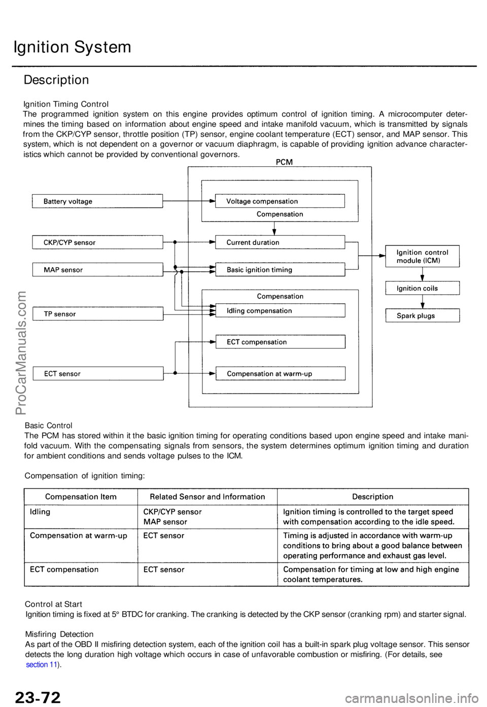
Ignition Timin g Contro l
Th e programme d ignitio n syste m o n thi s engine provide s optimu m contro l o f ignitio n timing . A microcompute r deter -
mine s th e timin g base d o n informatio n abou t engin e spee d an d intak e manifol d vacuum , whic h i s transmitte d b y signal s
fro m th e CKP/CY P sensor , throttl e positio n (TP ) sensor , engin e coolan t temperatur e (ECT ) sensor , an d MA P sensor . Thi s
system , whic h i s no t dependen t o n a governo r o r vacuu m diaphragm , i s capabl e o f providin g ignitio n advanc e character -
istic s whic h canno t b e provide d b y conventiona l governors .
Basic Contro l
The PC M ha s store d withi n it th e basi c ignitio n timin g fo r operatin g condition s base d upo n engin e spee d an d intak e mani -
fol d vacuum . Wit h th e compensatin g signal s fro m sensors , th e syste m determine s optimu m ignitio n timin g an d duratio n
fo r ambien t condition s an d send s voltag e pulse s t o th e ICM .
Compensatio n o f ignitio n timing :
Contro l a t Star t
Ignitio n timin g is fixe d a t 5 ° BTD C fo r cranking . Th e crankin g is detecte d b y th e CK P senso r (crankin g rpm ) an d starte r signal .
Misfirin g Detectio n
A s par t o f th e OB D II misfirin g detectio n system , eac h o f th e ignitio n coi l ha s a built-i n spar k plu g voltag e sensor . Thi s senso r
detect s th e lon g duratio n hig h voltag e whic h occur s in cas e o f unfavorabl e combustio n o r misfiring . (Fo r details , se e
section 11 ).
ProCarManuals.com
Page 596 of 1771
Ignition Syste m
Ignition Timin g Inspectio n
SRS component s ar e locate d in thi s area . Revie w th e SR S
componen t locations , precautions , an d procedure s i n th e
SR S (sectio n 24 ) befor e performin g repair s o r service .
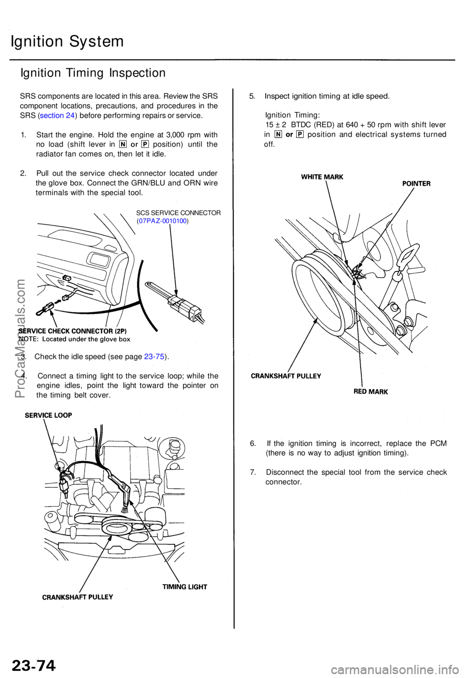
1 . Star t th e engine . Hol d th e engin e a t 3,00 0 rp m wit h
no loa d (shif t leve r i n position ) unti l th e
radiato r fa n come s on , the n le t i t idle .
2 . Pul l ou t th e servic e chec k connecto r locate d unde r
th e glov e box . Connec t th e GRN/BL U an d OR N wir e
terminal s wit h th e specia l tool .
SCS SERVIC E CONNECTO R
( 07PAZ -0010100 )
5. Inspec t ignitio n timin g a t idl e speed .
Ignition Timing :
1 5 ± 2 BTD C (RED ) a t 64 0 + 50 rp m wit h shif t leve r
in positio n an d electrica l system s turne d
off.
6. I f th e ignitio n timin g i s incorrect , replac e th e PC M
(ther e i s n o wa y t o adjus t ignitio n timing) .
7 . Disconnec t th e specia l too l fro m th e servic e chec k
connector .
3
. Chec k th e idl e spee d (se e pag e 23-75 ).
4 . Connec t a timin g ligh t t o th e servic e loop ; whil e th e
engin e idles , poin t th e ligh t towar d th e pointe r o n
th e timin g bel t cover .
ProCarManuals.com
Page 598 of 1771
Ignition Syste m
Ignition Contro l Modul e (ICM ) Inpu t Tes t
NOTE : Se e sectio n 1 1 i f th e malfunctio n indicator lamp (MIL ) blinks . Disconnec t th e 8 P connecto r fro m th e ignitio n contro l
modul e (ICM) . Inspec t th e connecto r an d socke t terminal s to b e sur e the y ar e al l makin g goo d contact .
• I f an y terminal s ar e bent , loos e o r corroded , repai r the m a s necessary , an d rechec k th e system .
• I f th e terminal s loo k OK , mak e th e followin g inpu t test s a t th e connector .
I f a tes t indicate s a problem , fin d an d correc t th e cause , the n rechec k th e system .
I f al l th e inpu t tes t prov e OK , th e IC M mus t b e faulty ; replac e it .
ProCarManuals.com
Page 599 of 1771
Ignition Coi l Tes t
1. Wit h th e ignitio n switc h OFF .
2 . Remov e th e engin e cover , the n remov e th e ignitio n
coil .
3 . Usin g a n ohmmeter , measur e resistanc e betwee n
th e terminals . Replac e th e coi l i f th e resistanc e i s
no t withi n specification .
NOTE : Resistanc e wil l var y wit h th e coi l tempera -
ture ; specificatio n is a t 77° F (25°C) .
Primar y Windin g Resistanc e
(betwee n th e No . 1 an d No . 2 terminals )
0.9 -1. 1 ohm s
• I f th e resistanc e i s no t withi n specification ,
replac e th e coil .
• I f th e resistanc e i s OK , bu t othe r troubleshootin g
doesn' t revea l th e caus e o f th e problem , substi -
tut e a known-goo d ignitio n coi l an d chec k engin e
operatio n again .
I f th e engin e the n run s OK , replac e th e origina l
coil .
ProCarManuals.com
Page 600 of 1771
Ignition Syste m
Spark Plu g Inspectio n
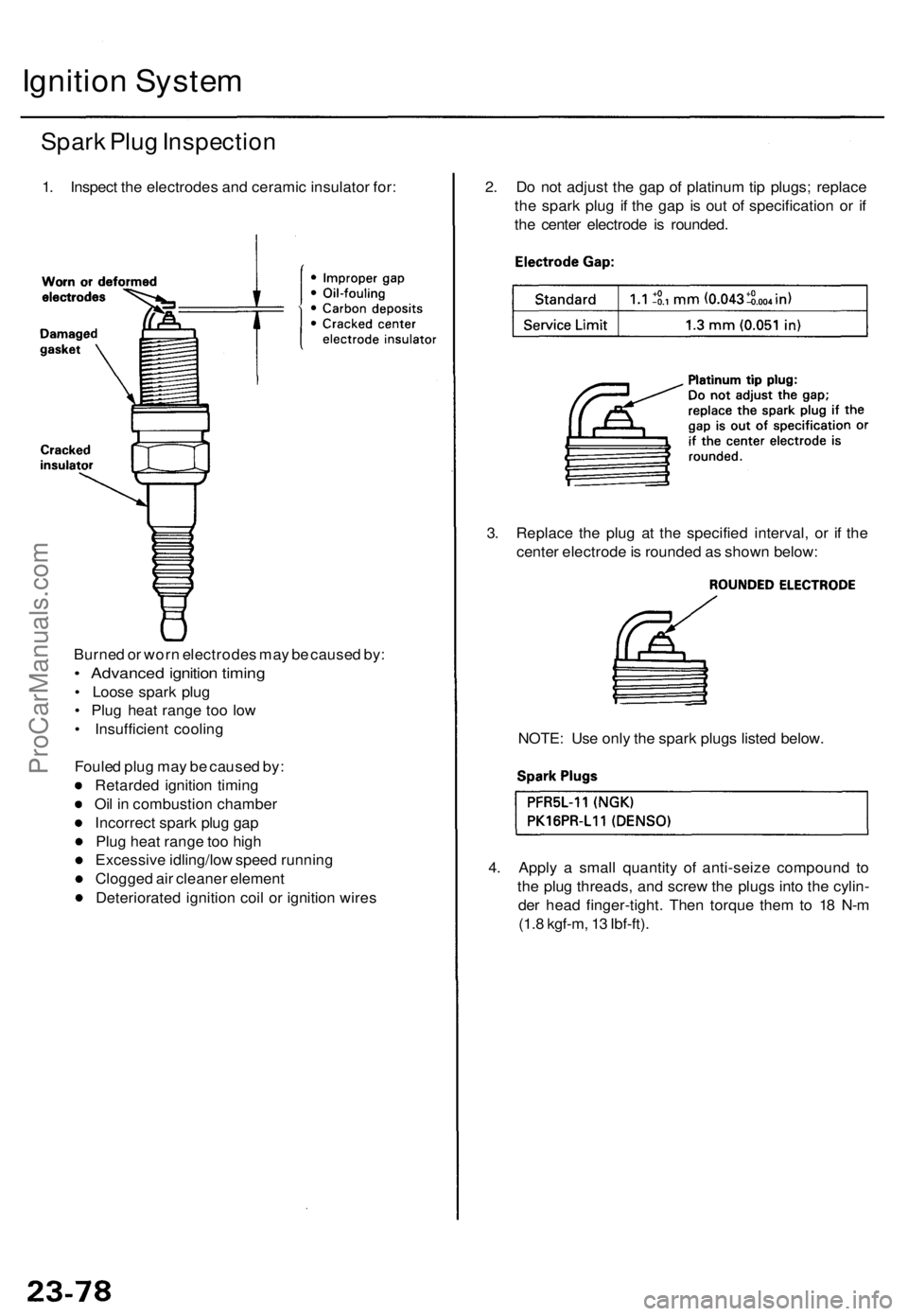
1. Inspec t th e electrode s an d cerami c insulato r for : 2. D o no t adjus t th e ga p o f platinu m tip plugs ; replac e
th e spar k plu g i f th e ga p i s ou t o f specificatio n o r i f
th e cente r electrod e i s rounded .
3 . Replac e th e plu g a t th e specifie d interval , o r i f th e
cente r electrod e is rounde d a s show n below :
4 . Appl y a smal l quantit y o f anti-seiz e compoun d t o
th e plu g threads , an d scre w th e plug s int o th e cylin -
de r hea d finger-tight . The n torqu e the m to 1 8 N- m
(1. 8 kgf-m , 1 3 Ibf-ft) .
NOTE
: Us e onl y th e spar k plug s liste d below .
Burne
d o r wor n electrode s ma y b e cause d by :
• Advance d ignitio n timin g
• Loos e spar k plu g
• Plu g hea t rang e to o lo w
• Insufficien t coolin g
Foule d plu g ma y b e cause d by :
Retarde d ignitio n timin g
Oi l i n combustio n chambe r
Incorrec t spar k plu g ga p
Plu g hea t rang e to o hig h
Excessiv e idling/lo w spee d runnin g
Clogge d ai r cleane r elemen t
Deteriorate d ignitio n coi l o r ignitio n wire s
ProCarManuals.com
Page 661 of 1771
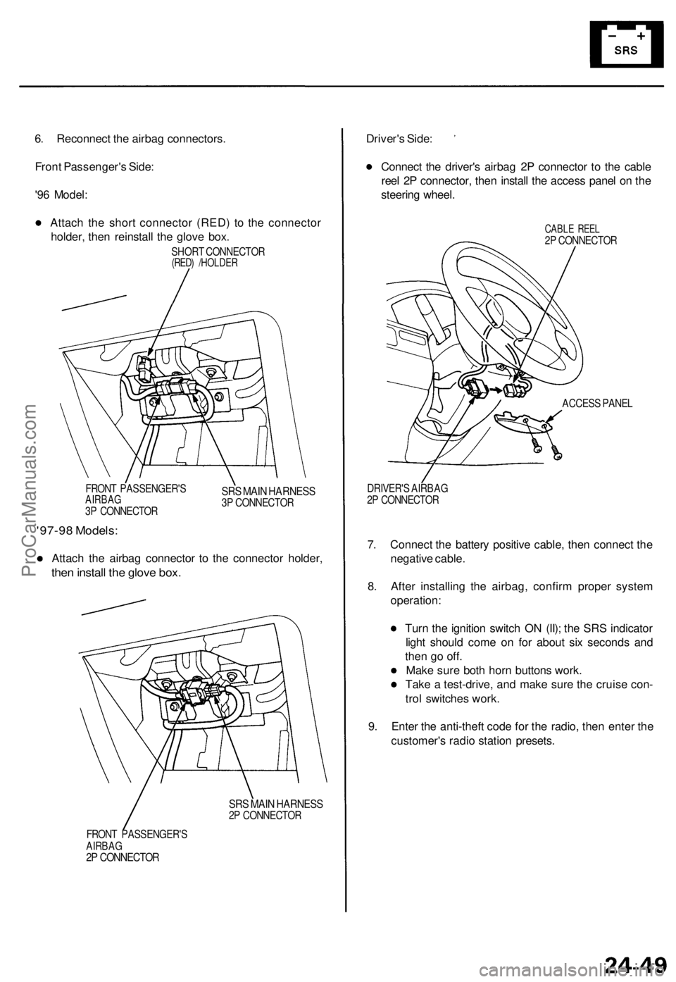
6. Reconnect the airbag connectors.
Front Passenger's Side:
'96 Model:
Attach the short connector (RED) to the connector
holder, then reinstall the glove box.
SHORT CONNECTOR
(RED) /HOLDER
FRONT PASSENGER'S
AIRBAG
3P CONNECTOR
SRS MAIN HARNESS
3P CONNECTOR
'97-98 Models:
Attach the airbag connector to the connector holder,
then install the glove box.
SRS MAIN HARNESS
2P CONNECTOR
FRONT PASSENGER'S
AIRBAG
2P CONNECTOR
Driver's Side:
Connect the driver's airbag 2P connector to the cable
reel 2P connector, then install the access panel on the
steering wheel.
CABLE REEL
2P CONNECTOR
ACCESS PANEL
DRIVER'S AIRBAG
2P CONNECTOR
7. Connect the battery positive cable, then connect the
negative cable.
8. After installing the airbag, confirm proper system
operation:
Turn the ignition switch ON (II); the SRS indicator
light should come on for about six seconds and
then go off.
Make sure both horn buttons work.
Take a test-drive, and make sure the cruise con-
trol switches work.
9. Enter the anti-theft code for the radio, then enter the
customer's radio station presets.ProCarManuals.com
Page 667 of 1771
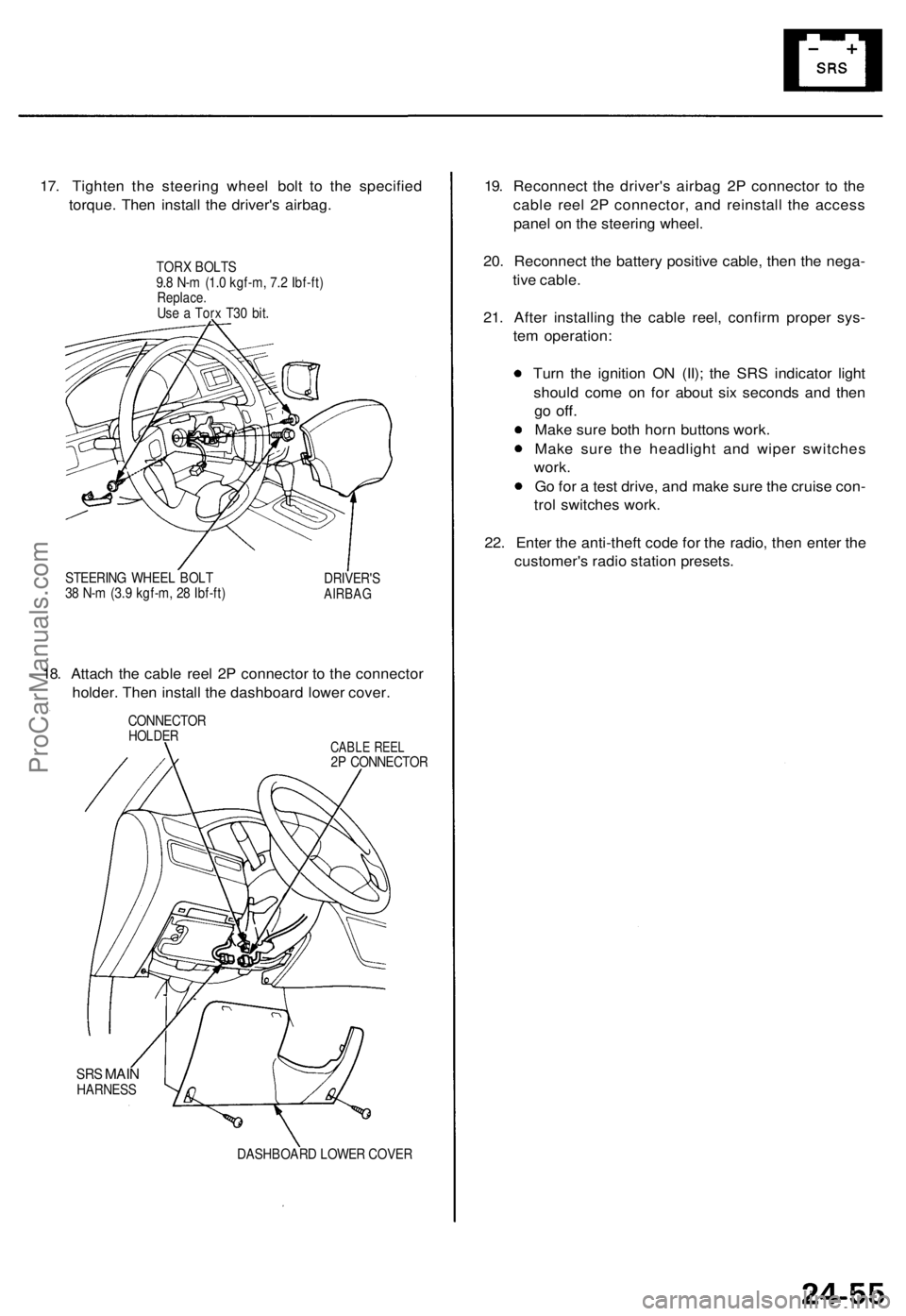
17. Tighten the steering wheel bolt to the specified
torque. Then install the driver's airbag.
TORX BOLTS
9.8 N-m (1.0 kgf-m, 7.2 Ibf-ft)
Replace.
Use a Torx T30 bit.
STEERING WHEEL BOLT
38 N-m (3.9 kgf-m, 28 Ibf-ft)
DRIVER'S
AIRBAG
18. Attach the cable reel 2P connector to the connector
holder. Then install the dashboard lower cover.
CONNECTOR
HOLDER
CABLE REEL
2P CONNECTOR
SRS
MAIN
HARNESS
DASHBOARD LOWER COVER
19. Reconnect the driver's airbag 2P connector to the
cable reel 2P connector, and reinstall the access
panel on the steering wheel.
20. Reconnect the battery positive cable, then the nega-
tive cable.
21. After installing the cable reel, confirm proper sys-
tem operation:
Turn the ignition ON (II); the SRS indicator light
should come on for about six seconds and then
go
off.
Make sure both horn buttons work.
Make sure the headlight and wiper switches
work.
Go for a test drive, and make sure the cruise con-
trol switches work.
22. Enter the anti-theft code for the radio, then enter the
customer's radio station presets.ProCarManuals.com