Page 1557 of 1771

Check for Wear and Damage
The starter should crank the engine smoothly and steadily.
If the starter engages, but cranks the engine erratically,
remove it, and inspect the starter drive gear and torque
converter ring gear for damage.
Check the drive gear overrunning clutch for binding or
slipping when the armature is rotated with the drive
gear held. If the clutch is damaged, replace the clutch
assembly.
Check Cranking Voltage and Current Draw
Cranking voltage should be no less than 8.5 volts.
Current draw should be no more than 380 amperes.
If cranking voltage is too low, or current draw too high,
check for:
Dead or low battery
Open circuit in starter armature commutator segments
Starter armature dragging
Shorted armature winding
Excessive drag in engine
Check Cranking rpm
Engine speed during cranking should be above 100 rpm.
If speed is too low, check for:
Loose battery or starter terminals
Excessively worn starter brushes
Open circuit in commutator segments
Dirty or damaged helical spline or drive gear
Defective drive gear overrunning clutch
Check Starter Disengagement
With the shift lever in turn the ignition switch to
"START (III)", and release to "ON (II)". The starter drive
gear should disengage from the drive plate/ring gear
when you release the key.
If the drive gear hangs up on the drive plate/ring gear,
check for:
• Solenoid plunger and switch malfunction
• Dirty drive gear assembly or damaged overrunning
clutchProCarManuals.com
Page 1566 of 1771
Ignition Syste m
Componen t Locatio n Inde x
IGNITIO N TIMIN G CONTRO L SYSTE M
Description , pag e 23-8 2
Inspection , pag e 23-8 4
IGNITIO N COI LTest , pag e 23-9 1 SERVIC
E CHEC K
CONNECTO R (2P )
[Wir e colors : GRN/BLU , ORN ]
IGNITIO N CONTRO L
MODUL E (ICM )
Inpu t Test , pag e 23-9 0DISTRIBUTO RTop En d Inspection , pag e 23-8 7
Removal/Installation , pag e 23-8 5 an d 23-8 9
Overhaul , pag e 23-8 6
NOIS E CONDENSE R
Test , pag e 23-8 7
TESTTACHOMETE R
CONNECTO R SPAR
K PLUG SInspection , pag e 23-9 2
IGNITIO N WIRE S
Inspectio n an d Test , pag e 23-8 8
ProCarManuals.com
Page 1567 of 1771

Ignition Syste m
Descriptio n
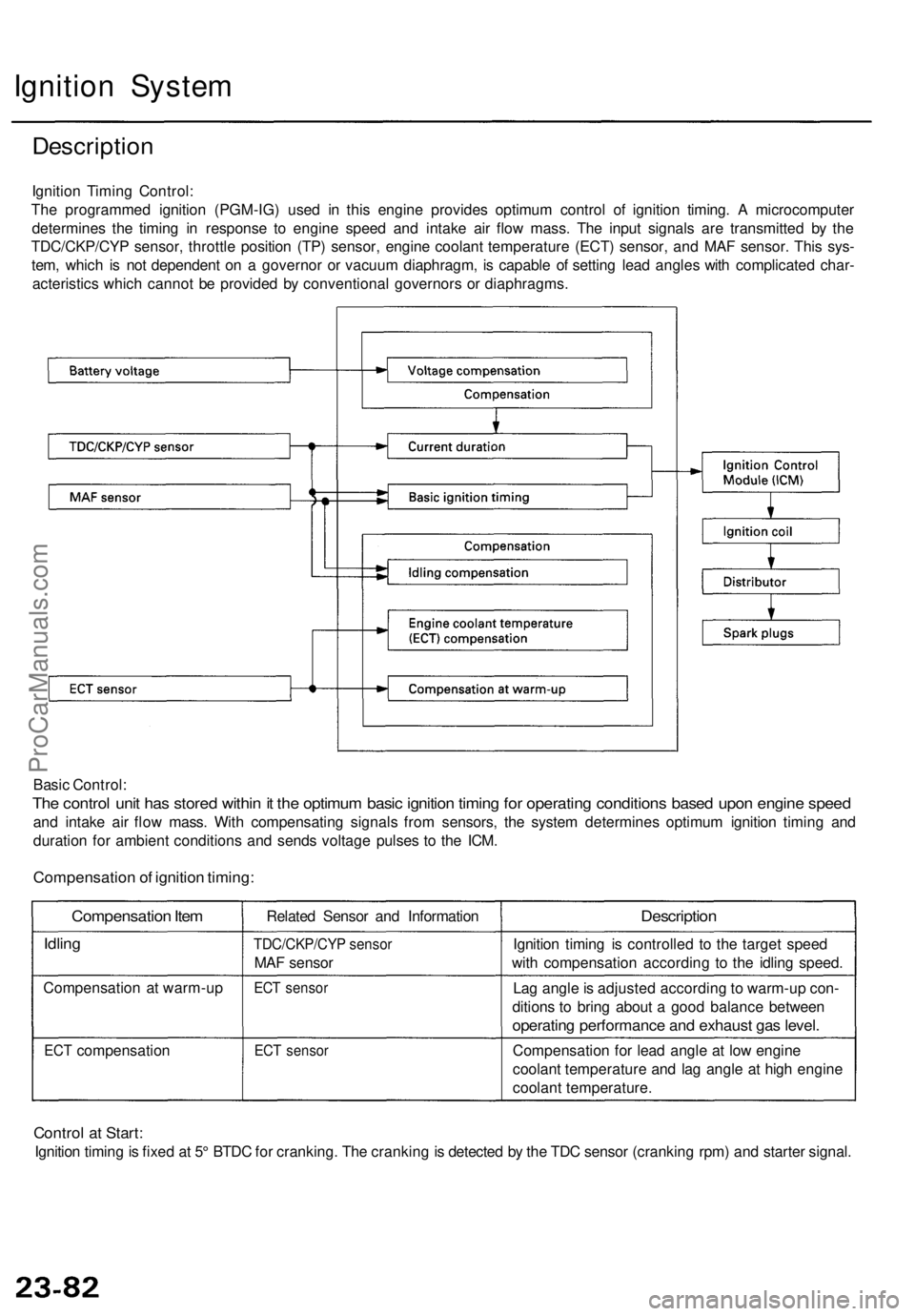
Ignition Timin g Control :
Th e programme d ignitio n (PGM-IG ) use d i n thi s engin e provide s optimu m contro l o f ignitio n timing . A microcompute r
determine s th e timin g i n respons e t o engin e spee d an d intak e ai r flo w mass . Th e inpu t signal s ar e transmitte d b y th e
TDC/CKP/CY P sensor , throttl e positio n (TP ) sensor , engine coolant temperatur e (ECT ) sensor , an d MA F sensor . Thi s sys -
tem , whic h i s no t dependen t o n a governo r o r vacuu m diaphragm , i s capabl e o f settin g lea d angle s wit h complicate d char -
acteristic s whic h canno t b e provide d b y conventiona l governor s o r diaphragms .
Basi c Control :
The contro l uni t ha s store d withi n it th e optimu m basi c ignitio n timin g fo r operatin g condition s base d upo n engin e spee d
and intak e ai r flo w mass . Wit h compensatin g signal s fro m sensors , th e syste m determine s optimu m ignitio n timin g an d
duratio n fo r ambien t condition s an d send s voltag e pulse s t o th e ICM .
Compensatio n of ignitio n timing :
Compensatio n Ite m
Idlin g
Compensatio n a t warm-u p
ECT compensatio n Relate
d Senso r an d Informatio n
TDC/CKP/CY P senso r
MAF senso r
ECT senso r
ECT senso r
Descriptio n
Ignition timin g i s controlle d t o th e targe t spee d
wit h compensatio n accordin g t o th e idlin g speed .
La g angl e is adjuste d accordin g t o warm-u p con -
dition s t o brin g abou t a goo d balanc e betwee n
operating performanc e an d exhaus t ga s level .
Compensatio n fo r lea d angl e a t lo w engin e
coolan t temperatur e an d la g angl e a t hig h engin e
coolan t temperature .
Control a t Start :
Ignitio n timin g is fixe d a t 5 ° BTD C fo r cranking . Th e crankin g is detecte d b y th e TD C senso r (crankin g rpm ) an d starte r signal .
ProCarManuals.com
Page 1568 of 1771

Ignition Syste m
Ignition Timin g Inspectio n
SRS component s ar e locate d in thi s area . Revie w th e SR S
componen t locations , precautions , an d procedure s i n th e
SR S (sectio n 24 ) befor e performin g repair s o r service .
1.
2 .
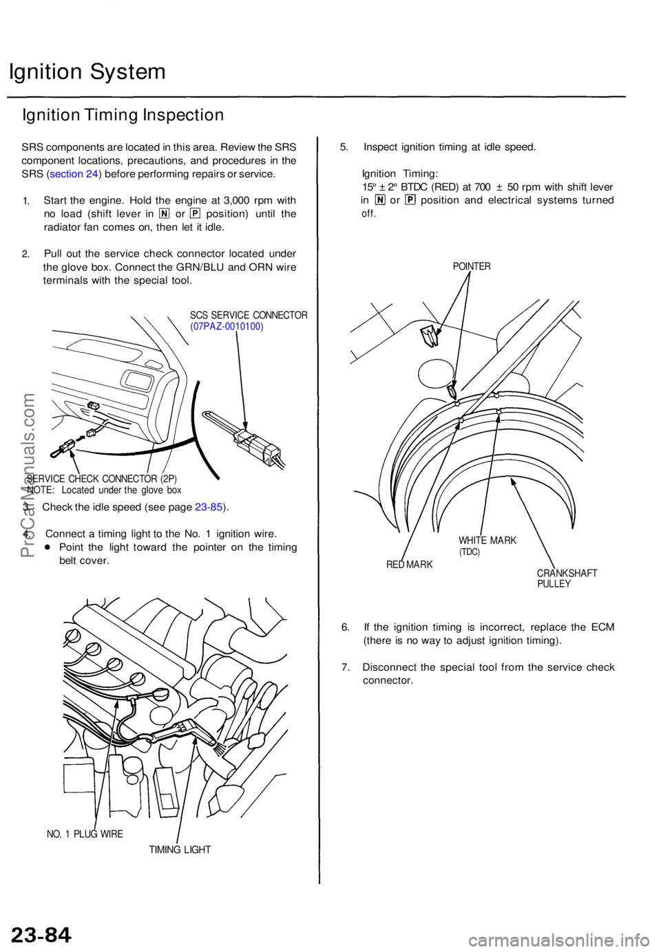
Star t th e engine . Hol d th e engine at 3,00 0 rp m wit h
no loa d (shif t leve r i n o r position ) unti l th e
radiato r fa n come s on , the n le t i t idle .
Pul l ou t th e servic e chec k connecto r locate d unde r
th e glov e box . Connec t th e GRN/BL U an d OR N wir e
terminal s wit h th e specia l tool .
SCS SERVIC E CONNECTO R
( 07PAZ-0010100 )
SERVIC E CHEC K CONNECTO R (2P)
NOTE : Locate d unde r th e glov e bo x
3. Chec k th e idl e spee d (se e pag e 23-85 ).
4 . Connec t a timin g ligh t t o th e No . 1 ignitio n wire .
Poin t th e ligh t towar d th e pointe r o n th e timin g
bel t cover .
NO. 1 PLU G WIR E
TIMIN G LIGH T
5. Inspec t ignitio n timin g a t idl e speed .
Ignitio n Timing :
15 ° ± 2° BTD C (RED ) a t 70 0 ± 50 rp m wit h shif t leve r
in o r positio n an d electrica l system s turne d
off.
POINTE R
RE D MAR K
CRANKSHAFT
PULLEY
6. I f th e ignitio n timin g i s incorrect , replac e th e EC M
(ther e is n o wa y t o adjus t ignitio n timing) .
7 . Disconnec t th e specia l too l fro m th e servic e chec k
connector .
WHITE MAR K(TDC)
ProCarManuals.com
Page 1569 of 1771
Idle Spee d Chec k
1. Star t th e engine . Hol d th e engin e a t 3,00 0 rp m wit h
no loa d (shif t leve r i n o r ) unti l th e radiato r fa n
come s on , the n le t i t idle .
2 . Connec t a tachomete r t o th e tes t tachomete r connec -
tor.
TES T TACHOMETE R CONNECTO R
TES T TACHOMETE R CONNECTO R
BATTERY
Idle speed : 70 0 ± 5 0 rp m wit h shif t leve r i n positio n
or an d electrica l system s turne d off .
3 . Adjus t th e idl e spee d if necessar y (se e sectio n 11 ).
Distributo r Remova l
1. Disconnec t th e ignitio n wire s fro m th e distributo r
ignition (Dl ) cap .
MOUNTIN GBOLTS
2. Remov e th e distributo r mountin g bolts , the n remov e
th e distributo r fro m th e cylinde r head .
CLIP
TACHOMETE R
ProCarManuals.com
Page 1570 of 1771
Ignition System
Distributor Overhaul
DISTRIBUTOR IGNITION (Dl)
CAP
Check for cracks, wear,
damage, and fouling;
if necessary, clean or
replace.
DISTRIBUTOR IGNITION (Dl)
ROTOR HEAD
O-RING
Replace.
DISTRIBUTOR IGNITION (Dl)
HOUSING
Check for cracks
and damage.
CARBON
POINT
CAP
SEAL
HEAT INSULATOR
CARBON
POINT SPRINGProCarManuals.com
Page 1571 of 1771
Distributor Top End Inspection
1. Check for rough or pitted rotor and cap terminals.
2. Scrape or file off the carbon deposits. Smooth the
rotor terminal with an oil stone or #600 sandpaper if
rough.
ROTOR
TERMINAL
CAP TERMINAL
CARBON
POINT
3. Check the distributor ignition (Dl) cap for cracks, wear,
and damage. If necessary, clean or replace it.
Noise Condenser Capacity Test
1. Use a commercially available condenser tester.
Connect the condenser tester probes and measure
the condenser capacity.
Condenser capacity: 0.47 ± 0.09 microfarads
POSITIVE TERMINAL
BODY GROUND
(Negative)
NOTE: The noise condenser is intended to reduce
ignition noise. However, condenser failure may cause
the engine to stop running.
2. If not within the specifications, replace the noise con-
denser.ProCarManuals.com
Page 1572 of 1771
Ignition System
Ignition Wire Inspection and Test
CAUTION: Carefully remove the ignition wires by pulling
on the rubber boots. Do not bend the wires; you might
break them inside.
1. Check the condition of the ignition wire terminals.
If any terminal is corroded, clean it, and if it is broken
or distorted, replace the wire.
Check for broken,
corroded, and bent
terminals.
IGNITION
WIRES
2. Connect ohmmeter probes and measure resistance.
Ignition Wire Resistance:
25k max. at 68°F (20°C)
IGNITION
WIRES
3. If resistance exceeds 25 k , replace the ignition wire.ProCarManuals.com