Page 1574 of 1771

Ignition Syste m
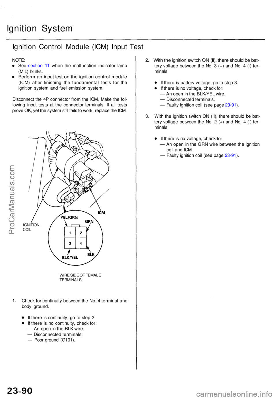
Ignition Contro l Modul e (ICM ) Inpu t Tes t
NOTE :
Se e sectio n 1 1 whe n th e malfunctio n indicator lamp
(MIL ) blinks .
Perform a n inpu t tes t o n th e ignitio n contro l modul e
(ICM) afte r finishin g th e fundamenta l test s fo r th e
ignitio n syste m an d fue l emissio n system .
Disconnec t th e 4 P connecto r fro m th e ICM . Mak e th e fol -
lowin g inpu t test s a t th e connecto r terminals . I f al l test s
prov e OK , ye t th e syste m stil l fail s to work , replac e th e ICM .
IGNITIO NCOIL
WIR E SID E O F FEMAL ETERMINAL S
Check fo r continuit y betwee n th e No . 4 termina l an d
bod y ground .
I f ther e is continuity , g o t o ste p 2 .
I f ther e i s n o continuity , chec k for :
— A n ope n in th e BL K wire .
— Disconnecte d terminals .
— Poo r groun d (G101) .
2. Wit h th e ignitio n switc h O N (II) , ther e shoul d b e bat -
tery voltag e betwee n th e No . 3 (+ ) an d No . 4 (- ) ter -
minals .
I f ther e is batter y voltage , g o t o ste p 3 .
I f ther e is n o voltage , chec k for :
— A n ope n in th e BLK/YE L wire .
— Disconnecte d terminals .
— Fault y ignitio n coi l (se e pag e 23-91 ).
3 . Wit h th e ignitio n switc h O N (II) , ther e shoul d b e bat -
ter y voltag e betwee n th e No . 2 (+ ) an d No . 4 (-) ter -
minals .
I f ther e is n o voltage , chec k for :
— A n ope n i n th e GR N wir e betwee n th e ignitio n
coi l an d ICM .
— Fault y ignitio n coi l (se e pag e 23-91 ).
ProCarManuals.com
Page 1575 of 1771
Ignition Coil Test
1. Turn the ignition switch OFF.
2. Disconnect the 4P connector and ignition coil wire.
SECONDARY
WINDING
TERMINAL
4P CONNECTOR
TERMINAL SIDE OF
MALE TERMINALS
3. Using an ohmmeter, measure resistance between
the terminals. Replace the coil if the resistance is
not within specifications.
NOTE: Resistance will vary with the coil tempera-
ture; specifications are at 68°F (20°C).
Primary Winding Resistance
(Between the No. 2 and No. 3 terminals):
0.36 - 0.44 ohms
Secondary Winding Resistance
(Between the No. 2 and secondary winding terminals):
10.8-16.2k
Resistance between the No. 3 and No. 4 terminals:
2.0-2.3k
SECONDARY
WINDING
TERMINAL
4. Check for continuity between the No. 1 and No. 2
terminals. Replace the coil if there is no continuity.ProCarManuals.com
Page 1576 of 1771
Ignition System
Spark Plug Inspection
1. Inspect the electrodes and ceramic insulator for:
2. Check the electrode gap.
• Adjust the gap with a suitable gapping tool.
Electrode Gap
• Replace the plug if the center electrode is rounded
as shown below:
Burned or worn electrodes may be caused by:
• Advanced ignition timing
• Loose spark plug
• Plug heat range too low
• Insufficient cooling
Fouled plug may be caused by:
Retarded ignition timing
Oil in combustion chamber
Incorrect spark plug gap
Plug heat range too high
Excessive idling/low speed running
Clogged air cleaner element
Deteriorated ignition coil or ignition wires
3. Apply a small quantity of anti-seize compound to
the plug threads, and screw the plugs into the cylin-
der head finger-tight. Then torque them to 18 N-m
(1.8 kgf-m, 13 Ibf-ft).
Spark PlugsProCarManuals.com
Page 1597 of 1771
Speedometer/Trip Meter/Odometer
Troubleshooting
NOTE:
The numbers in the table show the troubleshooting sequence.
If necessary, replace the speedometer, trip meter, and odometer as a unit.
VSS Input Test
Trml
Wire
Test condition
Test: Desired result
Possible cause if result is not obtained
1
2
3
BLK
YEL
ORN
Under all conditions
Ignition switch ON (II)
Ignition switch ON (II)
Check for continuity to ground:
There should be continuity.
Check for voltage to ground:
There should be battery voltage.
Check for voltage to ground:
There should be about 5 V or more.
• Poor ground (G101)
• An open in the wire
• Blown No. 1 (10 A) fuse in the
under-dash fuse/relay box
• Short to ground
• An open in the wire
• Short to ground
• An open in the wire
NOTE: A short to ground in the ORN wire can be caused by a short in any component connected to it.ProCarManuals.com
Page 1607 of 1771

Description
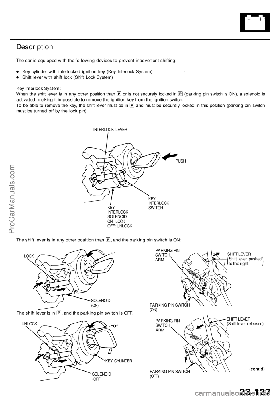
The car is equipped with the following devices to prevent inadvertent shifting:
Key cylinder with interlocked ignition key (Key Interlock System)
Shift lever with shift lock (Shift Lock System)
Key Interlock System:
When the shift lever is in any other position than or is not securely locked in (parking pin switch is ON), a solenoid is
activated, making it impossible to remove the ignition key from the ignition switch.
To be able to remove the key, the shift lever must be in and must be securely locked in this position (parking pin switch
must be turned off by the lock pin).
INTERLOCK LEVER
KEY
INTERLOCK
SOLENOID
ON: LOCK
OFF: UNLOCK
PUSH
KEY
INTERLOCK
SWITCH
The shift lever is in any other position than , and the parking pin switch is ON:
LOCK
SOLENOID
(ON)
The shift lever is in , and the parking pin switch is OFF.
UNLOCK
SOLENOID
(OFF)
PARKING PIN
SWITCH
ARM
PARKING PIN SWITCH
(ON)
PARKING PIN
SWITCH
ARM
PARKING PIN SWITCH
(OFF)
SHIFT LEVER
Shift lever pushed
to the right
SHIFT LEVER
(Shift lever released)
KEY CYLINDERProCarManuals.com
Page 1610 of 1771

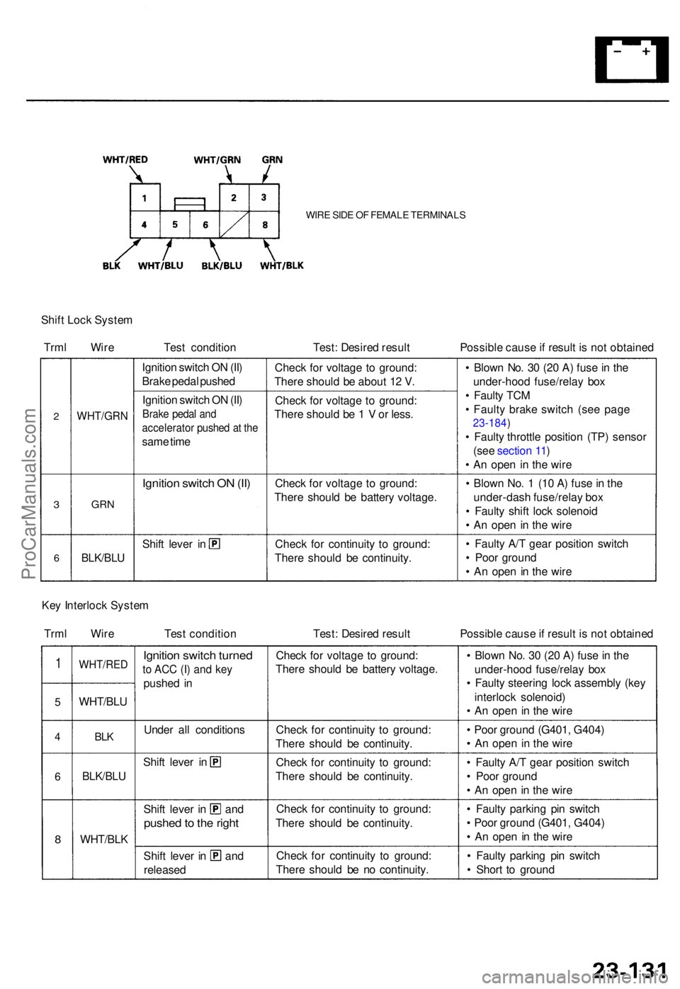
WIRE SID E O F FEMAL E TERMINAL S
Shift Loc k Syste m
Trm l Wir e Test conditio n Test: Desire d resul t Possible caus e if resul t i s no t obtaine d
2
3
6
WHT/GR N
GRN
BLK/BL U
Ignition switc h O N (II )
Brak e peda l pushe d
Ignitio n switc h O N (II )
Brak e peda l an d
accelerato r pushe d a t th e
sam e tim e
Ignitio n switc h O N (II )
Shif t leve r i n Chec
k fo r voltag e t o ground :
Ther e shoul d b e abou t 1 2 V .
Chec k fo r voltag e t o ground :
Ther e shoul d b e 1 V or less .
Chec k fo r voltag e t o ground :
Ther e shoul d b e batter y voltage .
Chec k fo r continuit y t o ground :
Ther e shoul d b e continuity . •
Blow n No . 3 0 (2 0 A ) fus e in th e
under-hoo d fuse/rela y bo x
• Fault y TC M
• Fault y brak e switc h (se e pag e
23-184 )
• Fault y throttl e positio n (TP ) senso r
(se e sectio n 11 )
• A n ope n i n th e wir e
• Blow n No . 1 (1 0 A ) fus e in th e
under-das h fuse/rela y bo x
• Fault y shif t loc k solenoi d
• A n ope n i n th e wir e
• Fault y A/ T gea r positio n switc h
• Poo r groun d
• A n ope n i n th e wir e
Ke y Interloc k Syste m
Trm l Wir e Tes t conditio n Test: Desire d resul t Possible caus e if resul t i s no t obtaine d
1
5
4
6
8
WHT/RE D
WHT/BLU
BLK
BLK/BL U
WHT/BL K
Ignition switc h turne d
to AC C (I ) an d ke y
pushe d i n
Unde r al l condition s
Shift leve r i n
Shif t leve r i n an d
pushed to th e righ t
Shift leve r i n an d
release d
Check fo r voltag e t o ground :
Ther e shoul d b e batter y voltage .
Chec k fo r continuit y t o ground :
Ther e shoul d b e continuity .
Chec k fo r continuit y t o ground :
Ther e shoul d b e continuity .
Chec k fo r continuit y t o ground :
Ther e shoul d b e continuity .
Chec k fo r continuit y t o ground :
Ther e shoul d b e n o continuity .•
Blow n No . 3 0 (2 0 A ) fus e in th e
under-hoo d fuse/rela y bo x
• Fault y steerin g loc k assembl y (ke y
interloc k solenoid )
• A n ope n i n th e wir e
• Poo r groun d (G401 , G404 )
• A n ope n i n th e wir e
• Fault y A/ T gea r positio n switc h
• Poo r groun d
• A n ope n i n th e wir e
• Fault y parkin g pi n switc h
• Poo r groun d (G401 , G404 )
• A n ope n in th e wir e
• Fault y parkin g pi n switc h
• Shor t t o groun d
ProCarManuals.com
Page 1628 of 1771

Key-in Reminde r Syste m
Entry Ligh t Time r Syste m
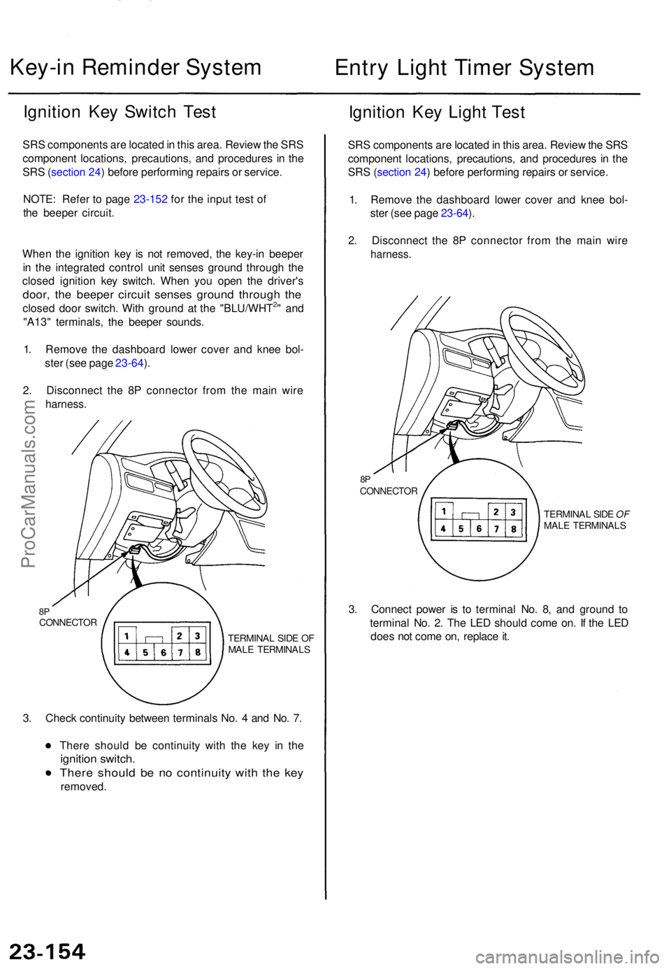
Ignition Ke y Switc h Tes t
SRS component s ar e locate d in thi s area . Revie w th e SR S
componen t locations , precautions , an d procedure s i n th e
SR S (sectio n 24 ) befor e performin g repair s o r service .
NOTE : Refe r t o pag e 23-152 for the input test of
the beepe r circuit.
Whe n th e ignitio n ke y i s no t removed , th e key-i n beepe r
i n th e integrate d contro l uni t sense s groun d throug h th e
close d ignitio n ke y switch . Whe n yo u ope n th e driver' s
door, th e beepe r circui t sense s groun d throug h th e
close d doo r switch . Wit h groun d a t th e "BLU/WHT2" an d
"A13 " terminals , th e beepe r sounds .
1 . Remov e th e dashboar d lowe r cove r an d kne e bol -
ste r (se e pag e 23-64 ).
2 . Disconnec t th e 8 P connecto r fro m th e mai n wir e
harness .
8PCONNECTO R
TERMINAL SID E O F
MAL E TERMINAL S
3. Chec k continuit y betwee n terminal s No . 4 an d No . 7 .
Ther e shoul d b e continuit y wit h th e ke y i n th e
ignitio n switch .
There shoul d b e n o continuit y wit h th e ke y
removed .
Ignition Ke y Ligh t Tes t
SRS component s ar e locate d in thi s area . Revie w th e SR S
componen t locations , precautions , an d procedure s i n th e
SR S (sectio n 24 ) befor e performin g repair s o r service .
1 . Remov e th e dashboar d lowe r cove r an d kne e bol -
ste r (se e pag e 23-64 ).
2 . Disconnec t th e 8 P connecto r fro m th e mai n wir e
harness .
8PCONNECTO R
TERMINAL SID E OF
MAL E TERMINAL S
3. Connec t powe r i s t o termina l No . 8 , an d groun d t o
termina l No . 2 . Th e LE D shoul d com e on . I f th e LE D
doe s no t com e on , replac e it .
ProCarManuals.com
Page 1696 of 1771
Troubleshooting (With Keyless Entry) ('98 model)
NOTE: The numbers in the table show the troubleshooting sequence.
CAUTION: To prevent damage to the motor, apply battery voltage only momentarily.
NOTE:
When the remote transmitter button is pressed the first time, only the driver's door will unlock. When the button is
pressed the second time, all the doors will unlock.
The doors will relock automatically after 20 seconds if a door is not opened, or the key is out of the ignition switch.
The keyless entry system will not lock the doors when the key is in the ignition switch.ProCarManuals.com