1994 JEEP CHEROKEE instrument cluster
[x] Cancel search: instrument clusterPage 645 of 1784
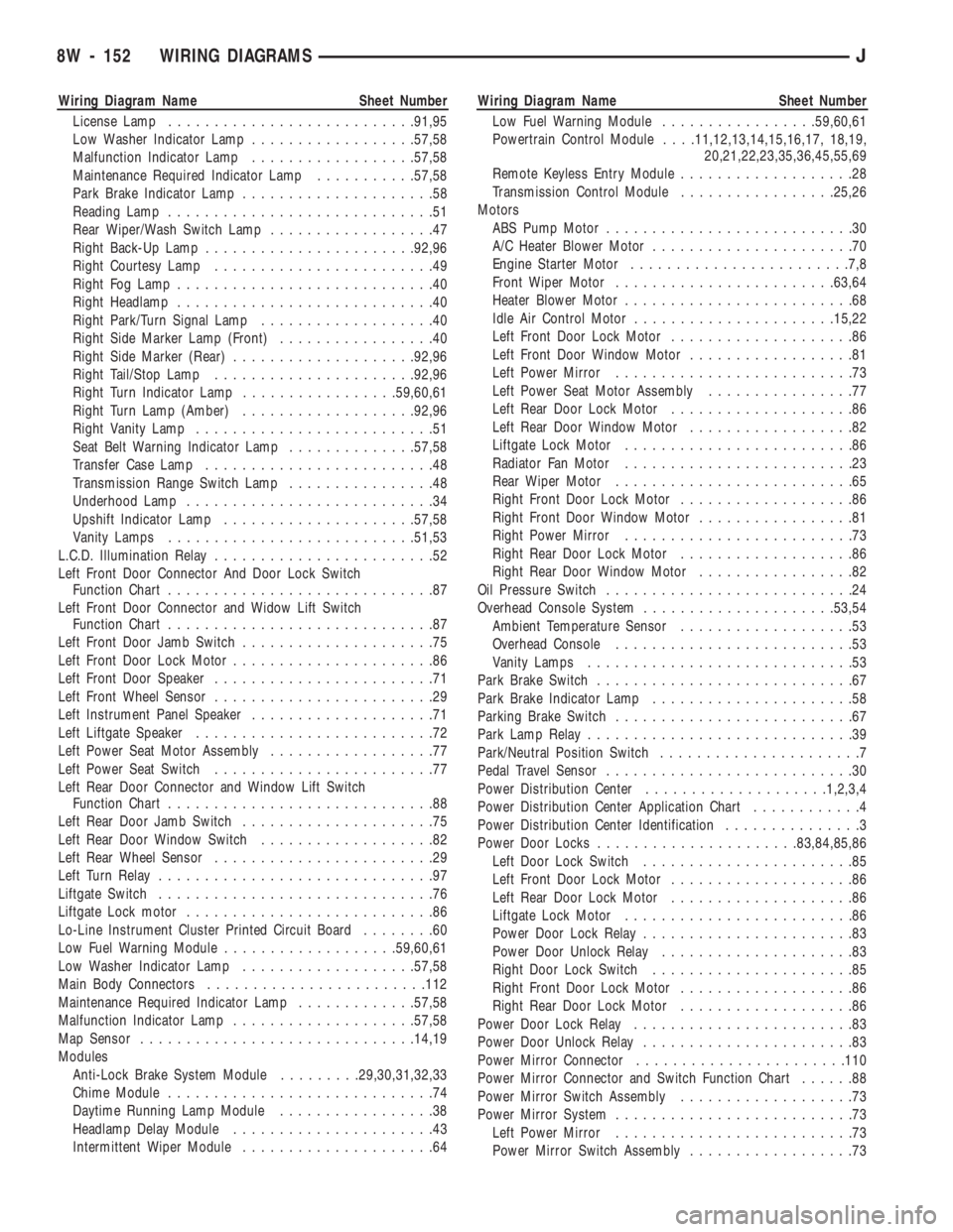
Wiring Diagram Name Sheet Number
License Lamp...........................91,95
Low Washer Indicator Lamp..................57,58
Malfunction Indicator Lamp..................57,58
Maintenance Required Indicator Lamp...........57,58
Park Brake Indicator Lamp.....................58
Reading Lamp.............................51
Rear Wiper/Wash Switch Lamp..................47
Right Back-Up Lamp.......................92,96
Right Courtesy Lamp........................49
Right Fog Lamp............................40
Right Headlamp............................40
Right Park/Turn Signal Lamp...................40
Right Side Marker Lamp (Front).................40
Right Side Marker (Rear)....................92,96
Right Tail/Stop Lamp......................92,96
Right Turn Indicator Lamp.................59,60,61
Right Turn Lamp (Amber)...................92,96
Right Vanity Lamp..........................51
Seat Belt Warning Indicator Lamp..............57,58
Transfer Case Lamp.........................48
Transmission Range Switch Lamp................48
Underhood Lamp...........................34
Upshift Indicator Lamp.....................57,58
Vanity Lamps...........................51,53
L.C.D. Illumination Relay........................52
Left Front Door Connector And Door Lock Switch
Function Chart.............................87
Left Front Door Connector and Widow Lift Switch
Function Chart.............................87
Left Front Door Jamb Switch.....................75
Left Front Door Lock Motor......................86
Left Front Door Speaker........................71
Left Front Wheel Sensor........................29
Left Instrument Panel Speaker....................71
Left Liftgate Speaker..........................72
Left Power Seat Motor Assembly..................77
Left Power Seat Switch........................77
Left Rear Door Connector and Window Lift Switch
Function Chart.............................88
Left Rear Door Jamb Switch.....................75
Left Rear Door Window Switch...................82
Left Rear Wheel Sensor........................29
Left Turn Relay..............................97
Liftgate Switch..............................76
Liftgate Lock motor...........................86
Lo-Line Instrument Cluster Printed Circuit Board........60
Low Fuel Warning Module...................59,60,61
Low Washer Indicator Lamp...................57,58
Main Body Connectors........................112
Maintenance Required Indicator Lamp.............57,58
Malfunction Indicator Lamp....................57,58
Map Sensor..............................14,19
Modules
Anti-Lock Brake System Module.........29,30,31,32,33
Chime Module.............................74
Daytime Running Lamp Module.................38
Headlamp Delay Module......................43
Intermittent Wiper Module.....................64Wiring Diagram Name Sheet Number
Low Fuel Warning Module.................59,60,61
Powertrain Control Module. . . .11,12,13,14,15,16,17, 18,19,
20,21,22,23,35,36,45,55,69
Remote Keyless Entry Module...................28
Transmission Control Module.................25,26
Motors
ABS Pump Motor...........................30
A/C Heater Blower Motor......................70
Engine Starter Motor........................7,8
Front Wiper Motor........................63,64
Heater Blower Motor.........................68
Idle Air Control Motor......................15,22
Left Front Door Lock Motor....................86
Left Front Door Window Motor..................81
Left Power Mirror..........................73
Left Power Seat Motor Assembly................77
Left Rear Door Lock Motor....................86
Left Rear Door Window Motor..................82
Liftgate Lock Motor.........................86
Radiator Fan Motor.........................23
Rear Wiper Motor..........................65
Right Front Door Lock Motor...................86
Right Front Door Window Motor.................81
Right Power Mirror.........................73
Right Rear Door Lock Motor...................86
Right Rear Door Window Motor.................82
Oil Pressure Switch...........................24
Overhead Console System.....................53,54
Ambient Temperature Sensor...................53
Overhead Console..........................53
Vanity Lamps.............................53
Park Brake Switch............................67
Park Brake Indicator Lamp......................58
Parking Brake Switch..........................67
Park Lamp Relay.............................39
Park/Neutral Position Switch......................7
Pedal Travel Sensor...........................30
Power Distribution Center....................1,2,3,4
Power Distribution Center Application Chart............4
Power Distribution Center Identification...............3
Power Door Locks......................83,84,85,86
Left Door Lock Switch.......................85
Left Front Door Lock Motor....................86
Left Rear Door Lock Motor....................86
Liftgate Lock Motor.........................86
Power Door Lock Relay.......................83
Power Door Unlock Relay.....................83
Right Door Lock Switch......................85
Right Front Door Lock Motor...................86
Right Rear Door Lock Motor...................86
Power Door Lock Relay........................83
Power Door Unlock Relay.......................83
Power Mirror Connector.......................110
Power Mirror Connector and Switch Function Chart......88
Power Mirror Switch Assembly...................73
Power Mirror System..........................73
Left Power Mirror..........................73
Power Mirror Switch Assembly..................73
8W - 152 WIRING DIAGRAMSJ
Page 647 of 1784
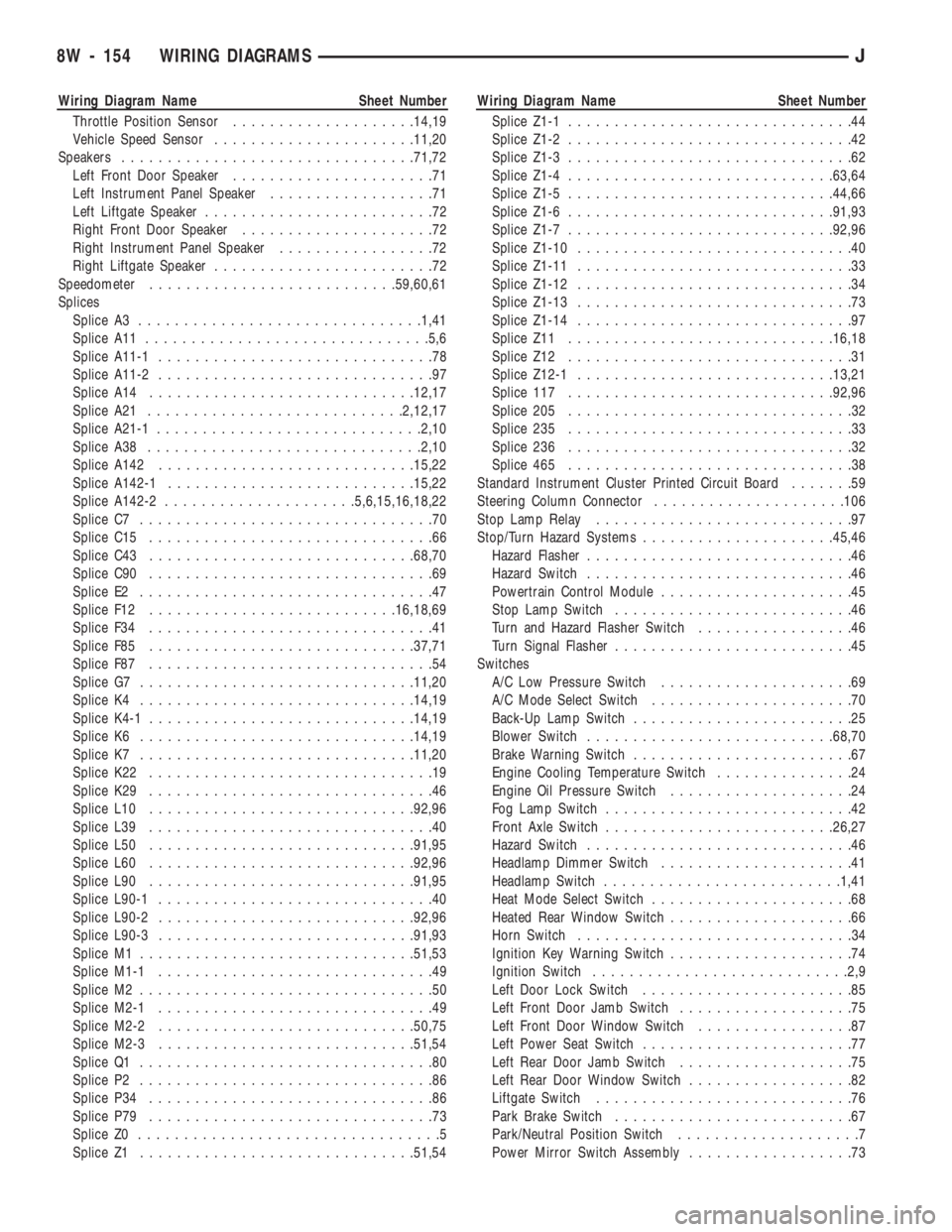
Wiring Diagram Name Sheet Number
Throttle Position Sensor....................14,19
Vehicle Speed Sensor......................11,20
Speakers................................71,72
Left Front Door Speaker......................71
Left Instrument Panel Speaker..................71
Left Liftgate Speaker.........................72
Right Front Door Speaker.....................72
Right Instrument Panel Speaker.................72
Right Liftgate Speaker........................72
Speedometer...........................59,60,61
Splices
Splice A3...............................1,41
Splice A11...............................5,6
Splice A11-1..............................78
Splice A11-2..............................97
Splice A14.............................12,17
Splice A21............................2,12,17
Splice A21-1.............................2,10
Splice A38..............................2,10
Splice A142............................15,22
Splice A142-1...........................15,22
Splice A142-2.....................5,6,15,16,18,22
Splice C7................................70
Splice C15...............................66
Splice C43.............................68,70
Splice C90...............................69
Splice E2................................47
Splice F12...........................16,18,69
Splice F34...............................41
Splice F85.............................37,71
Splice F87...............................54
Splice G7..............................11,20
Splice K4..............................14,19
Splice K4-1.............................14,19
Splice K6..............................14,19
Splice K7..............................11,20
Splice K22...............................19
Splice K29...............................46
Splice L10.............................92,96
Splice L39...............................40
Splice L50.............................91,95
Splice L60.............................92,96
Splice L90.............................91,95
Splice L90-1..............................40
Splice L90-2............................92,96
Splice L90-3............................91,93
Splice M1..............................51,53
Splice M1-1..............................49
Splice M2................................50
Splice M2-1..............................49
Splice M2-2............................50,75
Splice M2-3............................51,54
Splice Q1................................80
Splice P2................................86
Splice P34...............................86
Splice P79...............................73
Splice Z0.................................5
Splice Z1..............................51,54Wiring Diagram Name Sheet Number
Splice Z1-1...............................44
Splice Z1-2...............................42
Splice Z1-3...............................62
Splice Z1-4.............................63,64
Splice Z1-5.............................44,66
Splice Z1-6.............................91,93
Splice Z1-7.............................92,96
Splice Z1-10..............................40
Splice Z1-11..............................33
Splice Z1-12..............................34
Splice Z1-13..............................73
Splice Z1-14..............................97
Splice Z11.............................16,18
Splice Z12...............................31
Splice Z12-1............................13,21
Splice 117.............................92,96
Splice 205...............................32
Splice 235...............................33
Splice 236...............................32
Splice 465...............................38
Standard Instrument Cluster Printed Circuit Board.......59
Steering Column Connector.....................106
Stop Lamp Relay............................97
Stop/Turn Hazard Systems.....................45,46
Hazard Flasher.............................46
Hazard Switch.............................46
Powertrain Control Module.....................45
Stop Lamp Switch..........................46
Turn and Hazard Flasher Switch.................46
Turn Signal Flasher..........................45
Switches
A/C Low Pressure Switch.....................69
A/C Mode Select Switch......................70
Back-Up Lamp Switch........................25
Blower Switch...........................68,70
Brake Warning Switch........................67
Engine Cooling Temperature Switch...............24
Engine Oil Pressure Switch....................24
Fog Lamp Switch...........................42
Front Axle Switch.........................26,27
Hazard Switch.............................46
Headlamp Dimmer Switch.....................41
Headlamp Switch..........................1,41
Heat Mode Select Switch......................68
Heated Rear Window Switch....................66
Horn Switch..............................34
Ignition Key Warning Switch....................74
Ignition Switch............................2,9
Left Door Lock Switch.......................85
Left Front Door Jamb Switch...................75
Left Front Door Window Switch.................87
Left Power Seat Switch.......................77
Left Rear Door Jamb Switch...................75
Left Rear Door Window Switch..................82
Liftgate Switch............................76
Park Brake Switch..........................67
Park/Neutral Position Switch....................7
Power Mirror Switch Assembly..................73
8W - 154 WIRING DIAGRAMSJ
Page 764 of 1784
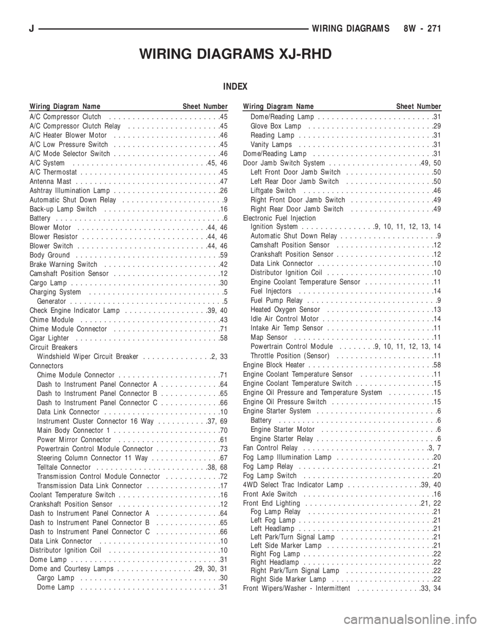
WIRING DIAGRAMS XJ-RHD
INDEX
Wiring Diagram Name Sheet Number
A/C Compressor Clutch........................45
A/C Compressor Clutch Relay....................45
A/C Heater Blower Motor.......................46
A/C Low Pressure Switch.......................45
A/C Mode Selector Switch.......................46
A/C System.............................45, 46
A/C Thermostat..............................45
Antenna Mast...............................47
Ashtray Illumination Lamp.......................26
Automatic Shut Down Relay......................9
Back-up Lamp Switch.........................16
Battery....................................6
Blower Motor............................44, 46
Blower Resistor...........................44, 46
Blower Switch............................44, 46
Body Ground...............................59
Brake Warning Switch.........................42
Camshaft Position Sensor.......................12
Cargo Lamp................................30
Charging System.............................5
Generator.................................5
Check Engine Indicator Lamp..................39, 40
Chime Module..............................43
Chime Module Connector.......................71
Cigar Lighter...............................58
Circuit Breakers
Windshield Wiper Circuit Breaker...............2,33
Connectors
Chime Module Connector......................71
Dash to Instrument Panel Connector A.............64
Dash to Instrument Panel Connector B.............65
Dash to Instrument Panel Connector C.............66
Data Link Connector.........................10
Instrument Cluster Connector 16 Way...........37, 69
Main Body Connector 1.......................70
Power Mirror Connector......................61
Powertrain Control Module Connector..............73
Steering Column Connector 11 Way...............67
Telltale Connector........................38, 68
Transmission Control Module Connector............72
Transmission Data Link Connector................17
Coolant Temperature Switch......................16
Crankshaft Position Sensor......................12
Dash to Instrument Panel Connector A..............64
Dash to Instrument Panel Connector B..............65
Dash to Instrument Panel Connector C..............66
Data Link Connector..........................10
Distributor Ignition Coil........................10
Dome Lamp................................31
Dome and Courtesy Lamps.................29, 30, 31
Cargo Lamp..............................30
Dome Lamp..............................31Wiring Diagram Name Sheet Number
Dome/Reading Lamp.........................31
Glove Box Lamp...........................29
Reading Lamp.............................31
Vanity Lamps.............................31
Dome/Reading Lamp..........................31
Door Jamb Switch System....................49, 50
Left Front Door Jamb Switch...................50
Left Rear Door Jamb Switch...................50
Liftgate Switch............................46
Right Front Door Jamb Switch..................49
Right Rear Door Jamb Switch..................49
Electronic Fuel Injection
Ignition System................9,10,11,12,13,14
Automatic Shut Down Relay.....................9
Camshaft Position Sensor.....................12
Crankshaft Position Sensor.....................12
Data Link Connector.........................10
Distributor Ignition Coil.......................10
Engine Coolant Temperature Sensor...............11
Fuel Injectors.............................14
Fuel Pump Relay............................9
Heated Oxygen Sensor.......................13
Idle Air Control Motor........................14
Intake Air Temp Sensor.......................11
Map Sensor..............................11
Powertrain Control Module........9,10,11,12,13,14
Throttle Position (Sensor).....................11
Engine Block Heater...........................58
Engine Coolant Temperature Sensor................11
Engine Coolant Temperature Switch.................15
Engine Oil Pressure and Temperature System..........15
Engine Oil Pressure Switch......................15
Engine Starter System..........................6
Battery..................................6
Engine Starter Motor.........................6
Engine Starter Relay..........................6
Fan Control Relay...........................3,7
Fog Lamp Illumination Lamp.....................20
Fog Lamp Relay.............................21
Fog Lamp Switch............................20
4WD Select Trac Indicator Lamp................39, 40
Front Axle Switch............................16
Front End Lighting.........................21, 22
Fog Lamp Relay...........................21
Left Fog Lamp.............................21
Left Headlamp.............................21
Left Park/Turn Signal Lamp....................21
Left Side Marker Lamp.......................21
Right Fog Lamp............................22
Right Headlamp............................22
Right Park/Turn Signal Lamp...................22
Right Side Marker Lamp......................22
Front Wipers/Washer - Intermittent..............33, 34
JWIRING DIAGRAMS 8W - 271
Page 765 of 1784
Wiring Diagram Name Sheet Number
Front Washer Pump.........................34
Front Wiper Motor..........................34
Intermittent Wiper Module.....................33
Park Switch..............................34
Washer Fluid Level Switch.....................33
Washer Switch............................33
Windshield Wiper/Washer Circuit Breaker...........33
Wiper/Washer Switch........................33
Fuel Gauge Sensor...........................54
Fuel Injectors...............................14
Fuel Pump.................................54
Fuel Pump Module...........................54
Fuel Pump Relay............................3,9
Fuel Tank System............................54
Full Time Indicator Lamp.....................39, 40
Fuse Application Chart........................1,2
Fuse Panel..............................62, 63
Fuses
Fuse #2.............................2,4,60
Fuse #4..........................2,33,44,46
Fuse #5.............................1,4,27
Fuse #6.............................1,4,51
Fuse #9...............................1,19
Fuse #10..............................1,19
Fuse #13............................2,47,58
Fuse #14.........................2,23,33,60
Fuse #19............................2,33,35
Fuse #25............................1,19,25
Fuse #26..........................1,8,37,43
F1 ...................................3,4
F2 ...................................3,9
F3 ...................................3,17
F4 ...................................3,4
F5 .................................3,6,17
F6 .................................3,9,10
F7 .....................................3
F8 ...................................3,4
F9 .....................................3
F10 ...................................3,4
F11 ...................................3,4
F12 ...................................3,4
F13 ...................................3,4
F14 ...................................3,4
F15 ...................................3,4
F16 ...................................3,4
Generator..................................5
Glove Box Lamp.............................29
Hazard Flasher..............................32
Headlamp Dimmer Switch.......................19
Headlamp Switch...........................1,19
Headlamp Switch System.....................19, 20
Fog Lamp Illumination........................20
Fog Lamp Switch...........................20
Headlamp Dimmer Switch.....................19
Headlamp Switch...........................19
Headlamps..............................21, 22
Heated Oxygen Sensor.........................13
Heated Rear Window..........................60Wiring Diagram Name Sheet Number
Relay...................................60
Switch..................................60
Switch Illumination..........................25
Heater A/C Panel Lamp........................25
Heater and A/C System......................45, 46
A/C Compressor Clutch.......................45
A/C Compressor Clutch Relay...................45
A/C Heater Blower Motor......................46
A/C Low Pressure Switch.....................45
A/C Mode Selector Switch.....................46
A/C Thermostat............................45
Blower Resistor............................46
Blower Switch.............................46
Powertrain Control Module.....................45
Heater System..............................44
Blower Resistor............................44
Blower Switch.............................44
Heater Blower Motor.........................44
Heat Mode Select Switch......................44
Heater Blower Motor..........................44
Heater Element..............................52
Heavy Duty Cooling (4.0L).......................7
Fan Control Relay...........................7
Powertrain Control Module.....................7
Radiator Fan Motor..........................7
High-Beam Indicator Lamp......................41
Horn System...............................27
Horn Brush/Slip Ring........................27
Horn Relay...............................27
Horn Switch..............................27
Left Side Horn.............................27
Right Side Horn............................27
Idle Air Control Motor.........................14
Ignition Key Warning Switch.....................43
Ignition Switch...............................8
Ignition System..............................8
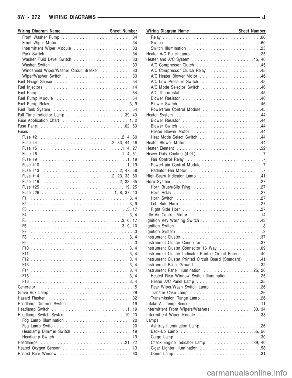
Instrument Cluster............................37
Instrument Cluster Connector.....................37
Instrument Cluster Connector 16 Way...............69
Instrument Cluster Indicator Printed Circuit Board.......40
Instrument Cluster Printed Circuit Board (Standard)......41
Instrument Panel Ground.......................32
Instrument Panel Illumination..................25, 26
Heated Rear Window Switch Illumination...........25
Heater A/C Panel Lamp.......................25
Rear Wiper/Wash Switch Lamp..................26
Transfer Case Lamp.........................26
Transmission Range Lamp.....................26
Intake Air Temp Sensor........................11
Intermittent Front Wipers/Washers...............33, 34
Intermittent Wiper Module.......................33
Lamps
Ashtray Illumination Lamp.....................26
Back-Up Lamp..........................55, 56
Cargo Lamp..............................30
Check Engine Indicator Lamp................39, 40
Cigar Lighter Illumination......................58
Dome Lamp..............................31
8W - 272 WIRING DIAGRAMSJ
Page 766 of 1784
Wiring Diagram Name Sheet Number
Dome/Reading Lamp.........................31
Fog Lamps............................21, 22
Fog Lamp Illumination Lamp...................20
4WD Select Trac Indicator Lamp..............39, 40
Front Headlamps.........................21, 22
Full Time Indicator Lamp...................39, 40
Glove Box Lamp...........................29
Heated Rear Window Lamp....................25
Heater A/C Panel Lamp.......................25
High-Beam Indicator Lamp.....................41
Instrument Cluster Illumination Lamps.............41
Left Backup Lamp..........................55
Left Fog Lamp.............................21
Left Headlamp.............................21
Left Park/Turn Signal Lamp....................21
Left Side Marker...........................55
Left Side Marker Lamp (Front)..................21
Left Tail/Stop Lamp.........................55
Left Turn Indicator Lamp......................41
Left Turn Lamp (Amber)......................55
License Lamp.............................55
Low Washer Indicator Lamp.................39, 40
Maintenance Required Indicator Lamp...........39, 40
Malfunction Indicator Lamp..................39, 40
Park Brake Indicator Lamp.....................40
Park/Turn Signal Lamps....................21, 22
Reading Lamp.............................31
Rear Wiper/Wash Switch Lamp..................26
Right Back-up Lamp.........................56
Right Fog Lamp............................22
Right Headlamp............................22
Right Park/Turn Signal Lamp...................22
Right Side Marker..........................56
Right Side Marker Lamp (Front).................22
Right Tail/Stop Lamp........................56
Right Turn Indicator Lamp.....................41
Right Turn Lamp (Amber).....................56
Seat Belt Indicator Lamp...................39, 40
Side Marker Lamps (Front)..................21, 22
Transfer Case Lamp.........................26
Transmission Range Lamp.....................26
Underhood Lamp...........................28
Upshift Indicator Lamp.....................39, 40
Vanity Lamps.............................31
LCD Illumination Relay.........................57
Left Front Door Jamb Switch.....................50
Left Rear Door Jamb Switch.....................50
Left Speakers............................47, 48
Liftgate Switch..............................50
Low Washer Indicator Lamp...................39, 40
Main Body Connector 1........................70
Maintenance Required Indicator Lamp............39, 40
Map Sensor................................11
Modules
Chime Module.............................43
Fuel Pump Module..........................54
Intermittent Wiper Module.....................33
Powertrain Control Module . .7, 9, 10, 11, 12, 13, 14, 45, 53Wiring Diagram Name Sheet Number
Transmission Control Module.................17, 18
Motors
A/C Heater Blower Motor......................46
Engine Starter Motor.........................6
Front Wiper Motor..........................34
Heater Blower Motor.........................44
Idle Air Control Motor........................14
Radiator Fan Motor..........................7
Rear Wiper Motor..........................36
Oil Pressure and Temperature System...............15
Coolant Temperature Switch....................15
Oil Pressure Switch.........................15
Park Brake Indicator Lamp......................40
Park Brake Switch............................42
Power Distribution Center........................1
Power Distribution Center Application Chart............4
Power Distribution Center Identification...............3
Power Mirror Connector........................61
Power Mirror Switch Assembly...................51
Power Mirrors............................51, 52
Heater Element............................52
Left Power Mirror..........................52
Right Power Mirror.........................52
Powertrain Control Module . . .7, 9, 10, 11, 12, 13, 14, 45, 53
Powertrain Control Module Connector...............73
Pumps
Front Washer.............................34
Rear Washer..............................35
Fuel...................................54
Radiator Fan Motor............................7
Radio.................................47, 48
Antenna Mast.............................47
Left Instrument Panel Speaker..................47
Left Liftgate Speaker.........................48
Radio..................................47
Right Instrument Panel Speaker.................48
Right Liftgate Speaker........................48
Rear Lighting............................55, 56
Left Back-Up Lamp..........................55
Left Side Marker...........................55
Left Tail/Stop Lamp.........................55
Left Turn Lamp (Amber)......................55
License Lamp.............................55
Right Back-Up Lamp.........................56
Right Side Marker..........................56
Right Tail/Stop Lamp........................56
Right Turn Lamp (Amber).....................56
Rear Wiper/Washer.........................35, 36
Rear Washer Pump.........................35
Rear Wiper Motor..........................36
Rear Wiper/Washer Switch.....................35
Reading Lamps..............................31
Relays
A/C Compressor Clutch Relay.................3,45
Automatic Shut Down Relay...................3,9
Engine Starter Relay........................3,6
Fan Control Relay.........................3,7
Fog Lamp Relay...........................21
JWIRING DIAGRAMS 8W - 273
Page 988 of 1784
SPEED CONTROLÐPCM OUTPUT
Speed control operation is regulated by the power-
train control module (PCM). The PCM controls the
vacuum to the throttle actuator through the speed
control vacuum and vent solenoids. Refer to Group
8H for speed control information.
TACHOMETERÐPCM OUTPUT
The powertrain control module (PCM) supplies en-
gine rpm values to the instrument cluster tachome-
ter (if equipped). Refer to Group 8E for tachometer
information.
TORQUE CONVERTER CLUTCH RELAYÐPCM
OUTPUT
ALL 2.5L 4 CYL. WITH 3-SPEED AUTO. TRANS
4.0L 6 CYL. YJ MODELS WITH 3-SPEED AUTO.
TRANS
The transmission mounted torque converter clutch
(TCC) solenoid is used to control the torque con-
verter. The solenoid is controlled through the power-
train control module (PCM) and by the TCC relay.
This relay is used only on vehicles equipped with a
3-speed automatic transmission.
An electrical output signal is sent from the PCM to
the TCC relay after the PCM receives information
from the vehicle speed, MAP, throttle position and
engine coolant temperature sensors. After the TCC
relay receives this necessary information, it will send
a signal to the torque converter clutch solenoid to
control the torque converter.
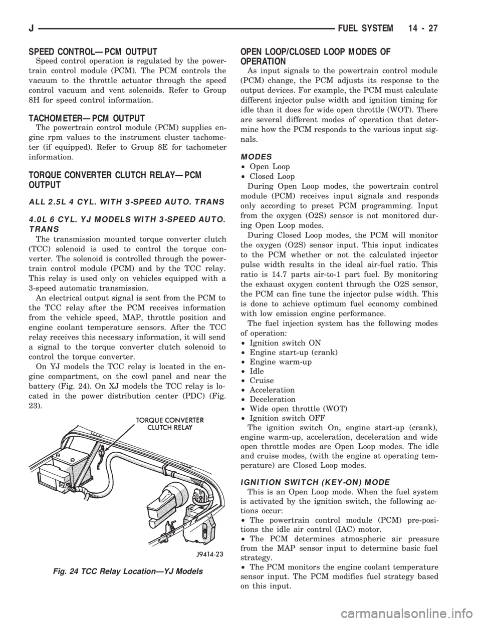
On YJ models the TCC relay is located in the en-
gine compartment, on the cowl panel and near the
battery (Fig. 24). On XJ models the TCC relay is lo-
cated in the power distribution center (PDC) (Fig.
23).
OPEN LOOP/CLOSED LOOP MODES OF
OPERATION
As input signals to the powertrain control module
(PCM) change, the PCM adjusts its response to the
output devices. For example, the PCM must calculate
different injector pulse width and ignition timing for
idle than it does for wide open throttle (WOT). There
are several different modes of operation that deter-
mine how the PCM responds to the various input sig-
nals.
MODES
²Open Loop
²Closed Loop
During Open Loop modes, the powertrain control
module (PCM) receives input signals and responds
only according to preset PCM programming. Input
from the oxygen (O2S) sensor is not monitored dur-
ing Open Loop modes.
During Closed Loop modes, the PCM will monitor
the oxygen (O2S) sensor input. This input indicates
to the PCM whether or not the calculated injector
pulse width results in the ideal air-fuel ratio. This
ratio is 14.7 parts air-to-1 part fuel. By monitoring
the exhaust oxygen content through the O2S sensor,
the PCM can fine tune the injector pulse width. This
is done to achieve optimum fuel economy combined
with low emission engine performance.
The fuel injection system has the following modes
of operation:
²Ignition switch ON
²Engine start-up (crank)
²Engine warm-up
²Idle
²Cruise
²Acceleration
²Deceleration
²Wide open throttle (WOT)
²Ignition switch OFF
The ignition switch On, engine start-up (crank),
engine warm-up, acceleration, deceleration and wide
open throttle modes are Open Loop modes. The idle
and cruise modes, (with the engine at operating tem-
perature) are Closed Loop modes.
IGNITION SWITCH (KEY-ON) MODE
This is an Open Loop mode. When the fuel system
is activated by the ignition switch, the following ac-
tions occur:
²The powertrain control module (PCM) pre-posi-
tions the idle air control (IAC) motor.
²The PCM determines atmospheric air pressure
from the MAP sensor input to determine basic fuel
strategy.
²The PCM monitors the engine coolant temperature
sensor input. The PCM modifies fuel strategy based
on this input.
Fig. 24 TCC Relay LocationÐYJ Models
JFUEL SYSTEM 14 - 27
Page 1546 of 1784
INTERIOR COMPONENTS
INDEX
page page
Assist HandleÐXJ Vehicles................ 118
B/C-Pillar and Liftgate Pillar Trim CoversÐ
XJ Vehicles.......................... 116
Bucket Seat Cushion and Cover............. 98
Bucket Seat Platform and Tracks........... 105
Bucket Seatback Cover and Frame.......... 100
Bucket Seatback Reconditioning............ 102
Carpets and Floor Mats................... 129
Dash Panel Insulation Panel................ 95
Front Bucket Seats....................... 97
Front Carpet/MatÐXJ Vehicles............. 129
Front Inner Scuff Plate/Cowl Side Trim PanelÐ
XJ Vehicles.......................... 114
Front Shoulder Belt/BuckleÐXJ Vehicles...... 119
Full Floor ConsoleÐXJ Vehicles............ 125
Headliner.............................. 121
I/P Ash Receiver Tray Lamp................ 92
I/P Tweeter Speaker/Courtesy Lamp Support
Bracket.............................. 95
Instrument Cluster Bezel................... 91
Instrument Cluster/Switch/Lighter/Radio/Hevac . . . 91
Instrument Panel......................... 93
Interior Trim Panels and Scuff PlatesÐXJ Vehicles. 112
Jack StorageÐXJ Vehicles................ 127
Mini-Floor ConsoleÐXJ Vehicles............ 124
Outer Scuff PlatesÐXJ Vehicles............ 118
Power Bucket Seat Components............ 106
Quarter and Wheelhouse Trim PanelsÐ
XJ Vehicles.......................... 115
Quarter Trim Panel ExtensionÐXJ Vehicles . . . 115
Rear Carpet/MatÐXJ Vehicles.............. 130
Rear Seat Cushion CoverÐXJ Vehicles...... 107
Rear Seat Cushion ReconditioningÐXJ Vehicles . 108
Rear Seat CushionÐXJ Vehicles............ 107
Rear Seatback CoverÐXJ Vehicles.......... 111
Rear Seatback Latch Striker and BumperÐ
XJ Vehicles.......................... 111
Rear Seatback ReconditioningÐXJ Vehicles . . . 111
Rear SeatbackÐXJ Vehicles............... 109
Rear Shoulder/Lap Belt/BuckleÐXJ Vehicles . . . 120
Spare Tire/Wheel Holddown and Floor BracketsÐ
XJ Vehicles.......................... 128
Sunvisors............................. 124
Windshield Side MouldingÐXJ Vehicles...... 114
INSTRUMENT CLUSTER BEZEL
REMOVAL
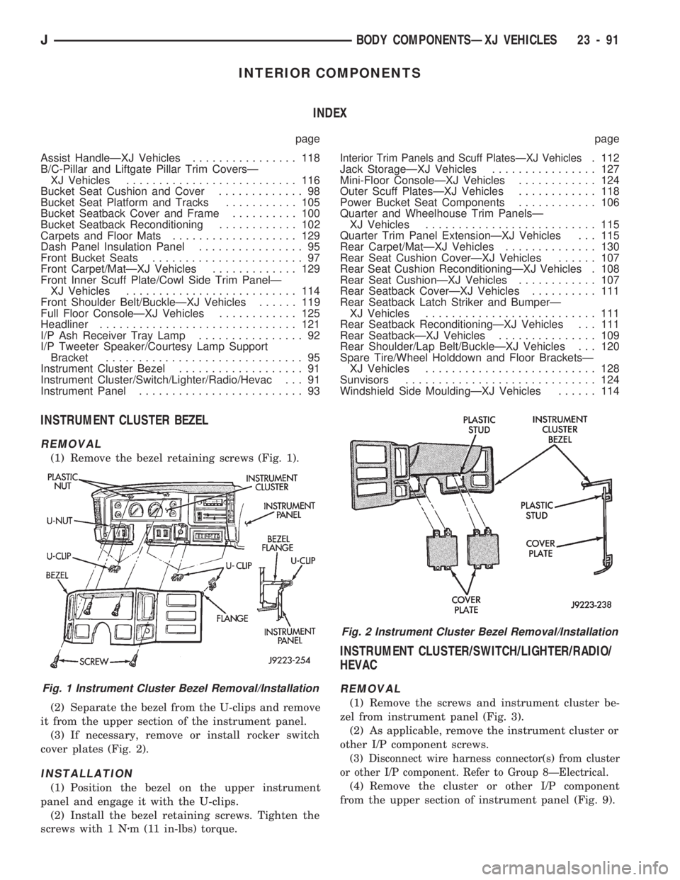
(1) Remove the bezel retaining screws (Fig. 1).
(2) Separate the bezel from the U-clips and remove
it from the upper section of the instrument panel.
(3) If necessary, remove or install rocker switch
cover plates (Fig. 2).
INSTALLATION
(1) Position the bezel on the upper instrument
panel and engage it with the U-clips.
(2) Install the bezel retaining screws. Tighten the
screws with 1 Nzm (11 in-lbs) torque.
INSTRUMENT CLUSTER/SWITCH/LIGHTER/RADIO/
HEVAC
REMOVAL
(1) Remove the screws and instrument cluster be-
zel from instrument panel (Fig. 3).
(2) As applicable, remove the instrument cluster or
other I/P component screws.
(3) Disconnect wire harness connector(s) from cluster
or other I/P component. Refer to Group 8ÐElectrical.
(4) Remove the cluster or other I/P component
from the upper section of instrument panel (Fig. 9).
Fig. 1 Instrument Cluster Bezel Removal/Installation
Fig. 2 Instrument Cluster Bezel Removal/Installation
JBODY COMPONENTSÐXJ VEHICLES 23 - 91
Page 1547 of 1784
INSTALLATION
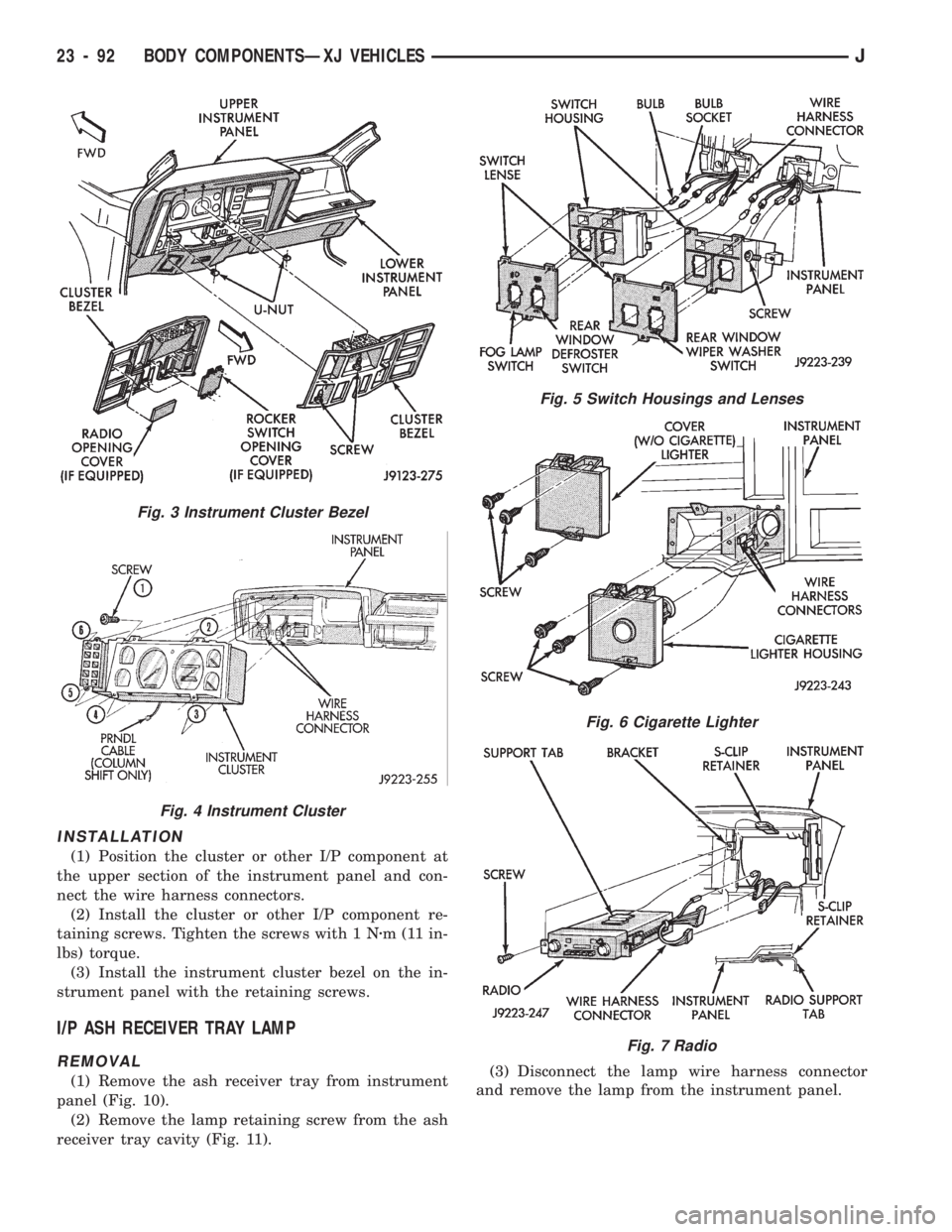
(1) Position the cluster or other I/P component at
the upper section of the instrument panel and con-
nect the wire harness connectors.
(2) Install the cluster or other I/P component re-
taining screws. Tighten the screws with 1 Nzm (11 in-
lbs) torque.
(3) Install the instrument cluster bezel on the in-
strument panel with the retaining screws.
I/P ASH RECEIVER TRAY LAMP
REMOVAL
(1) Remove the ash receiver tray from instrument
panel (Fig. 10).
(2) Remove the lamp retaining screw from the ash
receiver tray cavity (Fig. 11).(3) Disconnect the lamp wire harness connector
and remove the lamp from the instrument panel.
Fig. 5 Switch Housings and Lenses
Fig. 6 Cigarette Lighter
Fig. 7 Radio
Fig. 3 Instrument Cluster Bezel
Fig. 4 Instrument Cluster
23 - 92 BODY COMPONENTSÐXJ VEHICLESJ