1994 JEEP CHEROKEE instrument cluster
[x] Cancel search: instrument clusterPage 371 of 1784
GAUGE PACKAGE SERVICE PROCEDURES
PRINTED CIRCUIT REMOVAL
DISASSEMBLY
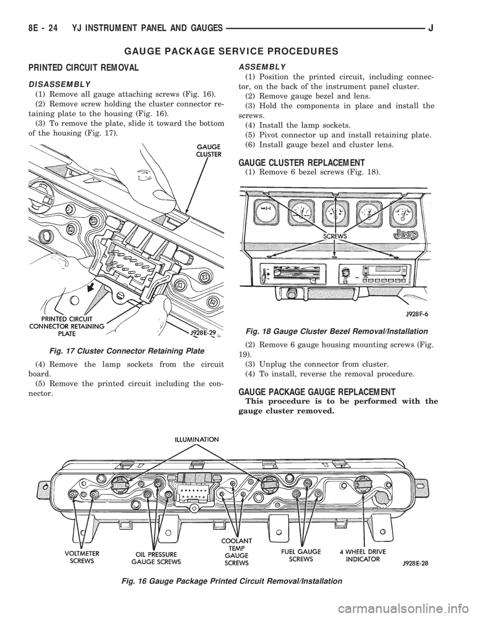
(1) Remove all gauge attaching screws (Fig. 16).
(2) Remove screw holding the cluster connector re-
taining plate to the housing (Fig. 16).
(3) To remove the plate, slide it toward the bottom
of the housing (Fig. 17).
(4) Remove the lamp sockets from the circuit
board.
(5) Remove the printed circuit including the con-
nector.
ASSEMBLY
(1) Position the printed circuit, including connec-
tor, on the back of the instrument panel cluster.
(2) Remove gauge bezel and lens.
(3) Hold the components in place and install the
screws.
(4) Install the lamp sockets.
(5) Pivot connector up and install retaining plate.
(6) Install gauge bezel and cluster lens.
GAUGE CLUSTER REPLACEMENT
(1) Remove 6 bezel screws (Fig. 18).
(2) Remove 6 gauge housing mounting screws (Fig.
19).
(3) Unplug the connector from cluster.
(4) To install, reverse the removal procedure.
GAUGE PACKAGE GAUGE REPLACEMENT
This procedure is to be performed with the
gauge cluster removed.
Fig. 16 Gauge Package Printed Circuit Removal/Installation
Fig. 17 Cluster Connector Retaining Plate
Fig. 18 Gauge Cluster Bezel Removal/Installation
8E - 24 YJ INSTRUMENT PANEL AND GAUGESJ
Page 372 of 1784
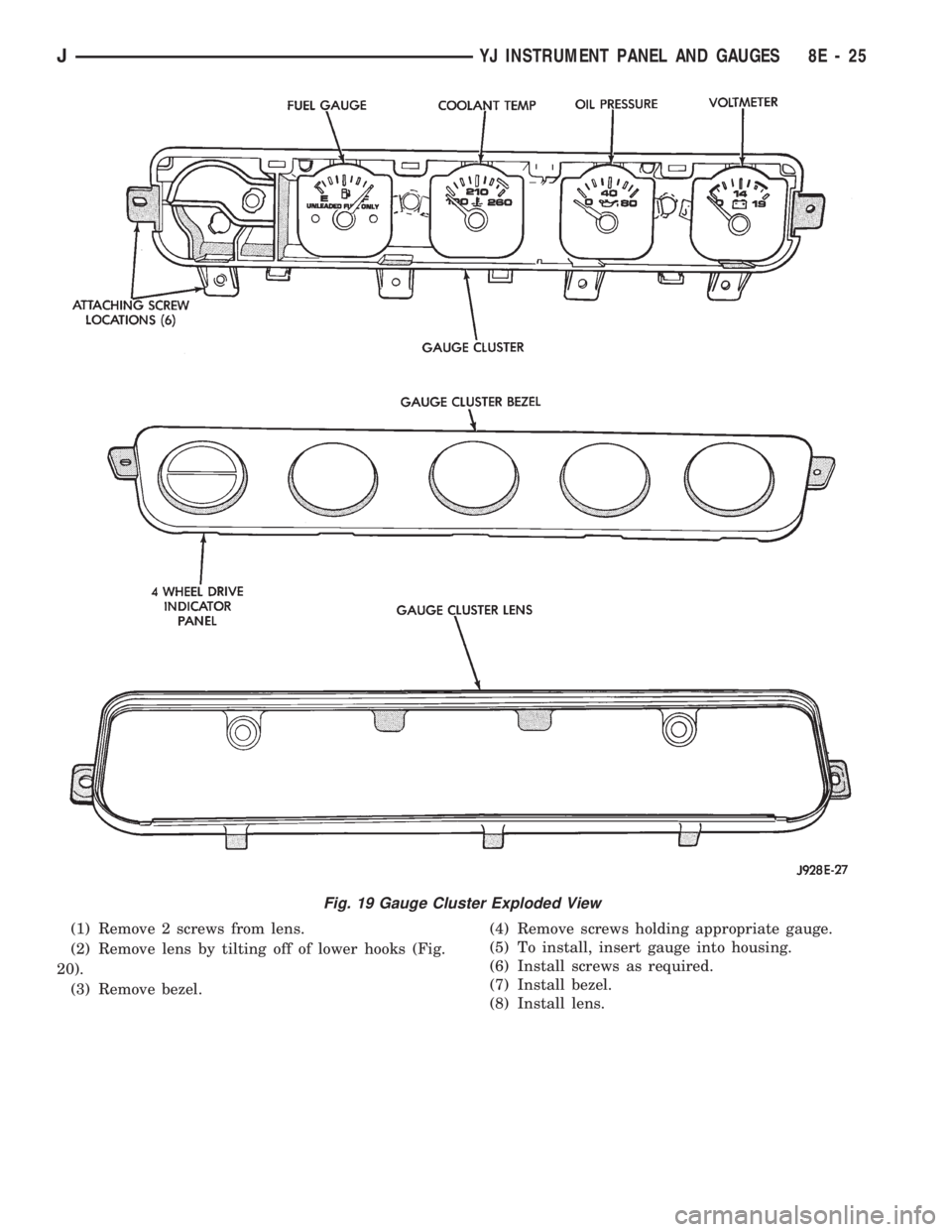
(1) Remove 2 screws from lens.
(2) Remove lens by tilting off of lower hooks (Fig.
20).
(3) Remove bezel.(4) Remove screws holding appropriate gauge.
(5) To install, insert gauge into housing.
(6) Install screws as required.
(7) Install bezel.
(8) Install lens.
Fig. 19 Gauge Cluster Exploded View
JYJ INSTRUMENT PANEL AND GAUGES 8E - 25
Page 374 of 1784
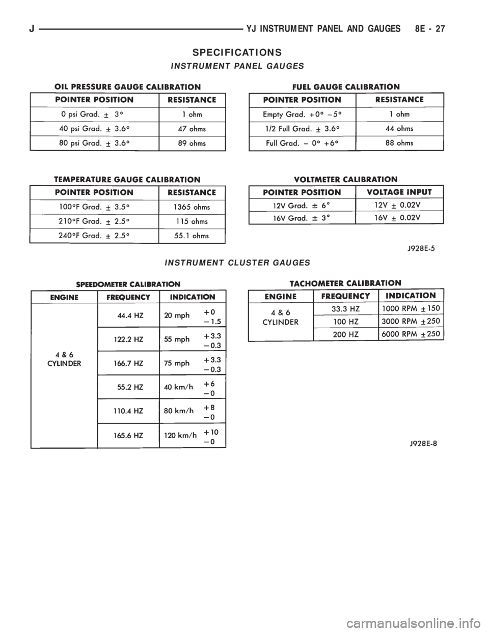
SPECIFICATIONS
INSTRUMENT PANEL GAUGES
INSTRUMENT CLUSTER GAUGES
JYJ INSTRUMENT PANEL AND GAUGES 8E - 27
Page 381 of 1784
INSTALLATION
(1) Connect speaker at wiring harness.
(2) Install speaker.
(3) Install trim panel by pushing in the plastic
trees.
(4) Install door panel screws.
YJ SERVICE PROCEDURES
RADIO REPLACEMENT
(1) Disconnect negative cable from battery.
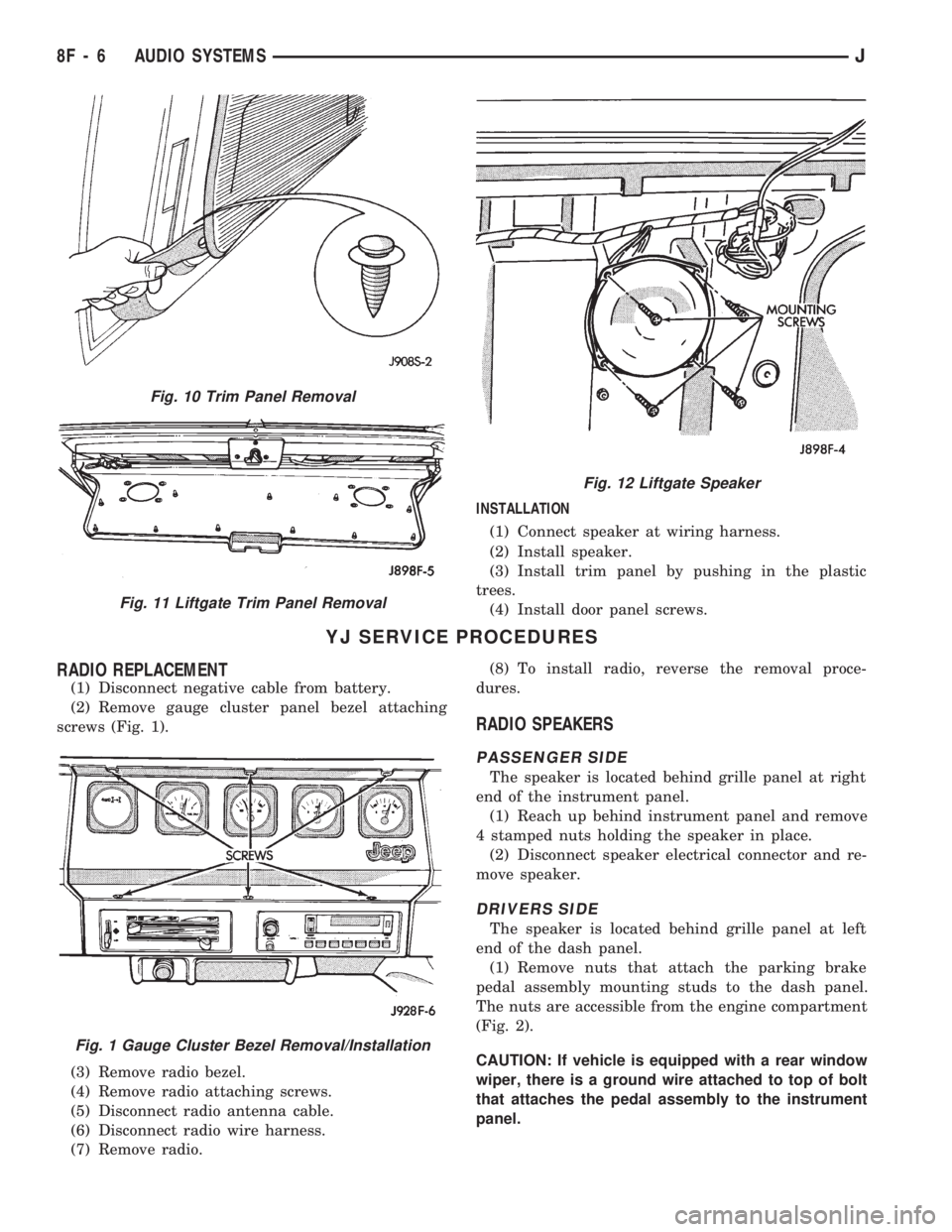
(2) Remove gauge cluster panel bezel attaching
screws (Fig. 1).
(3) Remove radio bezel.
(4) Remove radio attaching screws.
(5) Disconnect radio antenna cable.
(6) Disconnect radio wire harness.
(7) Remove radio.(8) To install radio, reverse the removal proce-
dures.
RADIO SPEAKERS
PASSENGER SIDE
The speaker is located behind grille panel at right
end of the instrument panel.
(1) Reach up behind instrument panel and remove
4 stamped nuts holding the speaker in place.
(2) Disconnect speaker electrical connector and re-
move speaker.
DRIVERS SIDE
The speaker is located behind grille panel at left
end of the dash panel.
(1) Remove nuts that attach the parking brake
pedal assembly mounting studs to the dash panel.
The nuts are accessible from the engine compartment
(Fig. 2).
CAUTION: If vehicle is equipped with a rear window
wiper, there is a ground wire attached to top of bolt
that attaches the pedal assembly to the instrument
panel.
Fig. 10 Trim Panel Removal
Fig. 11 Liftgate Trim Panel Removal
Fig. 12 Liftgate Speaker
Fig. 1 Gauge Cluster Bezel Removal/Installation
8F - 6 AUDIO SYSTEMSJ
Page 394 of 1784
TEST PROCEDURES
INDEX
page page
Checking for Diagnostic Trouble Code......... 5
Electrical Tests at Powertrain Control Module.... 6
Electrical Tests at Servo.................... 5
Inoperative System........................ 5
Operational Check (Road Test)............... 7
Road Test............................... 5Speed Control Switch (Turn Signal Lever) Test . . . 7
Stop Lamp Speed Control Switch Test......... 7
Vacuum Supply Test....................... 7
Vehicle Speed Control System Electrical Tests . . . 5
Vehicle Speed Sensor Test.................. 5
ROAD TEST
Refer to Operational Check (Road Test) section to
verify reports of speed control system malfunction.
INOPERATIVE SYSTEM
Road test vehicle to verify reports of speed control
system malfunction. An inspection should be made
for loose electrical and vacuum connections at the
servo.
Check for correct installation of the vacuum check
valve in the hose from servo to vacuum source. The
word VAC on the valve must point toward the vac-
uum source.
Corrosion should be removed from electrical termi-
nals and a light coating of Mopar MultiPurpose
Grease, or equivalent, applied.
Inspection also should be made to verify that both
ends of the speed control cable are securely attached.
CHECKING FOR DIAGNOSTIC TROUBLE CODE
(1) When trying to verify a speed control system
electronic malfunction use a DRB scan tool to find
the cause (refer to Powertrain Diagnostic Procedures
manual).
If DRB is not available, the Diagnostic Trouble
Code (DTC) may be determined with the following
method:
(a) With key inserted in ignition switch, cycle
switch to ON position 3 times. On third cycle, leave
switch in ON position.
(b) After switch has been cycled 3 times, observe
Malfunction Indicator Lamp (CHECK ENGINE)
on instrument cluster. If a DTC is present, the code
will be displayed in a series of flashes representing
digits. Three flashes in rapid succession, a slight
pause, then 4 flashes in rapid succession would in-
dicate DTC 34.
(2) If a DTC 34 is observed, perform tests in the
sections Electrical Tests at Servo and Electrical Tests
at Powertrain Control Module.
If a DTC 15 is observed, perform test for a faulty
vehicle speed sensor.
(3) Correct any problems found when performing
these tests and recheck for DTC if changes were
made.
VEHICLE SPEED SENSOR TEST
For testing of the vehicle speed sensor and related
components, refer to Powertrain Diagnostic Proce-
dures manual.
VEHICLE SPEED CONTROL SYSTEM ELECTRICAL
TESTS
Vehicle speed control systems may be tested using
two different methods. One involves use of a DRB
scan tool. If this test method is desired, refer to Pow-
ertrain Diagnostic Procedures manual.
The other test method uses a voltmeter. The volt-
meter method is described in the following tests.
If any information is needed concerning wiring, re-
fer to Section 8W - Wiring Diagrams.
CAUTION: When test probing for voltage or conti-
nuity at electrical connectors, care must be taken
not to damage connector, terminals, or seals. If
these components are damaged, intermittent or
complete system failure may occur.
ELECTRICAL TESTS AT SERVO
(1) Turn ignition switch to the ON position. With
speed control switch in the ON position, setup a volt-
meter to read battery voltage and connect negative
lead to a good chassis ground.
(2) Disconnect 4-way connector going to servo
(Figs. 2 and 3). Blue wire with red tracer of main
harness 4-way connector should read approximately
battery voltage. If not, check for loose connections,
brake switch adjustment or, repair main harness as
necessary.
(3) Connect a jumper wire between male and fe-
male terminals of blue wire with red tracer. The
other 3 male terminals from servo should show bat-
tery voltage. If not, replace servo.
(4) Using an ohmmeter, connect one lead to a good
body ground. Touch other lead to black wire terminal
in 4-way connector of main harness. Meter should
show continuity. If not, repair ground circuit as nec-
essary.
JVEHICLE SPEED CONTROL SYSTEM 8H - 5
Page 443 of 1784
switch is turned OFF. The driver engages the module
by turning the ignition switch OFF, then turning the
headlamps OFF.
The headlamp delay module is located behind the
I/P next to the headlamp switch.
HEADLAMP DELAY MODULE REPLACEMENTÐXJ
VEHICLES
The headlamp delay module is attached to the in-
side of the instrument panel to the right of the head-
lamp switch.
REMOVAL
(1) Remove the lower instrument panel.
(2) Remove the screw that attaches the module to
the inside of the instrument panel.
(3) Disconnect the wire harness connector and re-
move the module from the instrument panel.
INSTALLATION
(1) Position the module inside the I/P and connect
the wire harness connector to the module.
(2) Install the screw that attaches the module to
the inside of the instrument panel.(3) Remove the lower instrument panel.
HEADLAMP DELAY FUNCTION TROUBLE
DIAGNOSISÐXJ VEHICLES
DELAY FUNCTION INOPERATIVE
(1) Remove, inspect and test the HD LP DLY fuse.
Replace if defective.
(2) Remove the delay module from the I/P. Do not
disconnect the wire harness connector. Turn the igni-
tion switch to the RUN position. Place the headlamp
switch in headlamps ON position. Turn the ignition
to the OFF position for a resistance test.
(3) Measure the resistance from the delay module
terminal 4 to vehicle body ground. The ohmmeter
should indicate zero ohms. If not, repair the open cir-
cuit in the wire harness to vehicle body ground.
(4) Measure the voltage between the delay module
terminal 8 and vehicle body ground. The voltmeter
should indicate battery voltage. If not, repair the
open circuit in the wire harness to the instrument
cluster indicator connector terminal 14.
(5) Measure the voltage between the delay module
terminal 6 and vehicle body ground. The voltmeter
should indicate battery voltage. If not, repair the
open circuit in the wire harness to the headlamp
switch.
(6) Measure the voltage between the delay module
terminal 2 and vehicle body ground. The voltmeter
should indicate battery voltage. If not, repair the
open circuit in the wire harness to the fuse.
DAYTIME RUNNING LIGHTS (CANADA ONLY)
SERVICE INFORMATION
The Daytime Running Lights (Headlamps) System
is installed on vehicles manufactured for sale in Can-
ada only. The headlamps are illuminated when the
ignition switch is turned to the ON position. The
DRL module receives a vehicle-moving signal from
the vehicle speed sensor. This provides a constant
headlamps-oncondition as long as the vehicle is
moving. The lamps are illuminated at less than 50
percent of normal intensity.
DRL MODULE REPLACEMENT
REMOVALÐXJ VEHICLES
The Daytime Running Lights (DRL) module is lo-
cated on the right fender inner panel adjacent to the
dash panel (Fig. 45).
(1) Disconnect the wire harness connector from the
module.
(2) Remove the screws that attach the module to
the fender inner panel.
(3) Remove the module from the fender inner
panel.
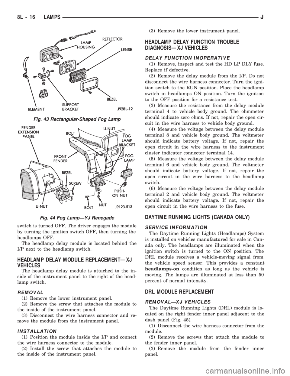
Fig. 43 Rectangular-Shaped Fog Lamp
Fig. 44 Fog LampÐYJ Renegade
8L - 16 LAMPSJ
Page 642 of 1784
WIRING DIAGRAMS XJ
INDEX
Wiring Diagram Name Sheet Number
A/C Compressor Clutch Relay...................3,69
A/C Compressor Clutch........................69
A/C Heater Blower Motor.......................70
A/C Low Pressure Switch.......................69
A/C Mode Select Switch........................70
A/C Thermostat..............................69
ABS Diode.................................33
ABS Green Indicator Lamp......................57
ABS Hydraulic Actuation Unit.....................33
ABS #1 Relay.............................3,31
ABS #2 Relay.............................3,31
ABS Pump Motor............................30
ABS Red Indicator Lamp.......................57
Ambient Temperature Sensor.....................53
Antenna...................................71
Antenna Mast...............................71
Anti-Lock Brake Control Module Connector...........109
Anti-Lock Braking System...............29,30,31,32,33
ABS Diode...............................33
ABS Relays...............................31
Anti-Lock Pump Motor.......................30
Anti-Lock Brake System Module.........29,30,31,32,33
Data Link Connector.........................32
G Sensor................................30
Hydraulic Actuation Unit......................33
Left Front Wheel Sensor......................29
Left Rear Wheel Sensor.......................29
Pedal Travel Sensor.........................30
Right Front Wheel Sensor.....................29
Right Rear Wheel Sensor......................29
Anti-Lock Brake System Module...........29,30,31,32,33
Anti-Lock Pump Motor.........................30
Anti-Lock Relay..............................31
Ashtray Lamp...............................48
Automatic Shut Down Relay..................3,12,17
Automatic Transmission Control System (2.5L).........27
Front Axle Lock-Up Switch.....................27
EMCC Relay..............................27
EMCC Solenoid............................27
Back-Up Lamp Switch.........................25
Ballast Resistor..............................89
Battery..................................1,7,8
Blower Motor.............................68,70
Blower Resistors...........................68,70
Blower Switch............................68,70
Body Ground...............................44
Brake Warning Switch.........................67
Bulkhead Disconnect.................101,102,103,104
Camshaft Position Sensor.....................11,20
Cargo Lamp................................50
Center High Mounted Stop Lamp..................98
Charging System 2.5L..........................5
Generator.................................5Wiring Diagram Name Sheet Number
Charging System 4.OL..........................6
Generator.................................6
Chime Module..............................74
Ignition Key Warning Switch....................74
Seat Belt Switch...........................74
Cigar Lighter...............................37
Cigar Lighter Lamp...........................48
Circuit Breakers
In Line Circuit Breaker........................2
Trailer Tow In-Line Circuit Breaker................97
Windshield Wiper Circuit Breaker...............63,64
Connectors
Anti-Lock Brake Control Module Connector.........109
Data Link Connector...................16,18,25,32
Instrument Cluster Connector................55,108
Main Body Connectors.......................112
Power Mirror Connector......................110
Powertrain Control Module Connector.............111
Remote Keyless Entry Module Connector...........114
Steering Column Connector...................106
Telltale Connector........................56,107
Trailer Tow Connector........................93
Transmission Control Module Connector...........105
Cooling Fan Relay...........................3,23
Courtesy Lamp..............................49
Crankshaft Position Sensor....................11,20
Data Link Connector....................16,18,25,32
Daytime Running Lamp Module (DRL)...............38
Daytime Running Lamp System...................38
Diode,ABS.................................33
Distributor Ignition Coil.......................16,18
Dome Lamp................................51
Dome And Courtesy Lamps..................49,50,51
Cargo Lamp..............................50
Dome Lamp..............................51
Dome/Reading Lamp.........................51
Glove Box Lamp...........................49
Left Courtesy Lamp.........................49
Reading Lamp.............................51
Right Courtesy Lamp........................49
Vanity Lamps.............................51
Dome Reading Lamp..........................51
Door Jamb Switch System....................75,76
Left Front Door Jamb Switch...................75
Left Rear Door Jamb Switch...................75
Liftgate Switch............................76
Right Front Door Jamb Switch..................76
Right Rear Door Jamb Switch..................76
EMCC Relay...............................3,27
EMCC Solenoid..............................27
Engine Block Coolant Heater/Cigar Lighter............37
Cigar Lighter..............................37
Engine Block Coolant Heater....................37
JWIRING DIAGRAMS 8W - 149
Page 644 of 1784
Wiring Diagram Name Sheet Number
Fuse #15...............................1,41
Fuse #17...........................2,10,55,74
Fuse #18...............................1,66
Fuse #19.............................1,41,47
Gauges
Engine Coolant Temperature Gauge...........59,60,61
Engine Oil Pressure Gauge.................59,60,61
Fuel Gauge...........................59,60,61
G Sensor..................................30
Generator.................................5,6
Glove Box Lamp.............................49
Hazard Flasher............................35,46
Headlamp Delay Module........................43
Headlamp Dimmer Switch.......................41
Headlamp Switch...........................41,42
Fog Lamp Illumination........................42
Fog Lamp Switch...........................42
Headlamp Dimmer Switch.....................41
Headlamp Switch...........................41
Headlamps...............................39,40
Heat Mode Select Switch.......................68
Heated Oxygen Sensor.......................13,21
Heated Rear Window..........................66
Relay...................................66
Grid...................................66
Switch..................................66
Heated Rear Window Switch Lamp.................47
Heater A/C Panel Lamp........................47
Heater and A/C System......................69,70
A/C Mode Selector Switch.....................70
A/C Compressor Clutch.......................69
A/C Compressor Clutch Relay...................69
A/C Heater Blower Motor......................70
A/C Thermostat............................69
A/C Low Pressure Switch.....................69
Blower Resistor............................70
Blower Switch.............................70
Powertrain Control Module.....................69
Heat Mode Select Switch.......................68
Heater Blower Motor..........................68
Heater,Engine Block...........................37
Heater System..............................68
Blower Resistor............................68
Blower Switch.............................68
Heater Blower Motor.........................68
Heater Mode Select Switch....................68
Heavy Duty Cooling 4.OL.......................23
Fan Control Relay...........................23
Powertrain Control Module.....................23
Radiator Fan Motor.........................23
High Beam Indicator Lamp..................59,60,61
High Beam Relay............................40
Hi-Line Instrument Cluster.......................61
Horn Brush/Slip Ring..........................34
Horn Relay................................34
Horn Switch................................34
Horns....................................34
Hydraulic Actuation Unit, ABS....................33Wiring Diagram Name Sheet Number
Idle Air Control Motor.......................15,22
Ignition Key Warning Switch.....................74
Ignition Switch..............................2,9
Ignition System............................9,10
Injectors................................15,22
In Line Circuit Breaker..........................2
Instrument Cluster............................55
Powertrain Control Module.....................55
Washer Fluid Level Switch.....................55
Instrument Cluster (Hi-Line)......................61
Instrument Cluster (Lo-Line).....................60
Instrument Cluster (Standard)....................59
Instrument Cluster Connector..................55,108
Instrument Cluster Printed Circuit Board (W/ABS).......57
Instrument Cluster Printed Circuit Board (W/O ABS)......58
Instrument Cluster Indicators.....................56
Instrument Panel Ground.......................62
Instrument Panel Illumination...................47,48
Ashtray Lamp.............................48
Cigar Lighter Lamp..........................48
Fog Lamp Illumination........................47
Heater A/C Panel Lamp.......................47
Heater Rear Window Switch Lamp................47
Rear Wiper Wash Switch Lamp..................47
Transfer Case Lamp.........................48
Transmission Range Switch Lamp................48
Intake Air Temperature Sensor..................14,19
Intermittent Front Wipers/Washers.................64
Intermittent Wiper Module.......................64
Lamps
ABS Green Indicator Lamp.....................57
ABS Red Indicator Lamp......................57
Ashtray Lamp.............................48
Cargo Lamp..............................50
Center High Mounted Stop Lamps................98
Cigar Lighter Lamp..........................48
Dome Lamp..............................51
Dome/Reading Lamp.........................51
Fog Lamp Illumination........................47
4WD Indicator Lamp.....................26,57,58
Full Time Indicator Lamp....................57,58
Glove Box Lamp...........................49
Heated Rear Window Switch Lamp...............47
Heater A/C Panel Lamp.......................47
High Beam Indicator Lamp.................59,60,61
Indicator Lamp 4WD.......................57,58
Instrument Cluster Illumination Lamps.........59,60,61
Left Back-Up Lamp........................91,93
Left Courtesy Lamp.........................49
Left Fog Lamp.............................39
Left Headlamp.............................39
Left Park/Turn Signal Lamp....................39
Left Side Marker Lamp (Front)..................39
Left Side Marker Lamp (Rear)................91,93
Left Tail/Stop Lamp.......................91,93
Left Turn Indicator Lamp..................59,60,61
Left Turn Lamp (Amber)....................91,93
Left Vanity Lamp...........................51
JWIRING DIAGRAMS 8W - 151