Page 353 of 1784

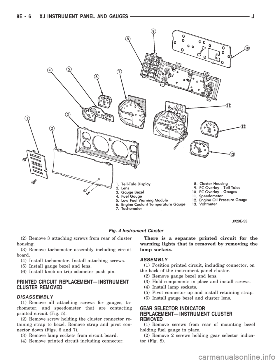
(2) Remove 3 attaching screws from rear of cluster
housing.
(3) Remove tachometer assembly including circuit
board.
(4) Install tachometer. Install attaching screws.
(5) Install gauge bezel and lens.
(6) Install knob on trip odometer push pin.
PRINTED CIRCUIT REPLACEMENTÐINSTRUMENT
CLUSTER REMOVED
DISASSEMBLY
(1) Remove all attaching screws for gauges, ta-
chometer, and speedometer that are contacting
printed circuit (Fig. 5).
(2) Remove screw holding the cluster connector re-
taining strap to bezel. Remove strap and pivot con-
nector down (Figs. 6 and 7).
(3) Remove lamp sockets from circuit board.
(4) Remove printed circuit including connector.There is a separate printed circuit for the
warning lights that is removed by removing the
lamp sockets.
ASSEMBLY
(1) Position printed circuit, including connector, on
the back of the instrument panel cluster.
(2) Remove gauge bezel and lens.
(3) Hold components in place and install screws.
(4) Install lamp sockets.
(5) Pivot connector up and install retaining strap.
(6) Install gauge bezel and cluster lens.
GEAR SELECTOR INDICATOR
REPLACEMENTÐINSTRUMENT CLUSTER
REMOVED
(1) Remove screws from rear of mounting bezel
holding fuel gauge in place.
(2) Remove 2 screws holding gear selector indica-
tor (Fig. 8).
Fig. 4 Instrument Cluster
8E - 6 XJ INSTRUMENT PANEL AND GAUGESJ
Page 354 of 1784
(3) Pull cable and clip through hole in the mount-
ing bezel and remove indicator.
(4) Install indicator and cluster.
(5) To adjust indicator, place transmission in PARK.(6) Align pointer on indicator with PARK position.
(7) Install clip to steering column shroud.
(8) Move transmission shift lever to check proper
alignment.
Fig. 5 Printed Circuit Removal/Installation
Fig. 6 Cluster Connector Retaining StrapFig. 7 Printed Circuit And Cluster Connector
JXJ INSTRUMENT PANEL AND GAUGES 8E - 7
Page 355 of 1784
INSTRUMENT PANEL REPLACEMENT (Fig. 9)
(1) Disconnect negative cable from battery.
(2) Remove:
²Parking brake release handle
²lower heat/AC duct below steering column
²ash receiver²lower instrument panel (Fig. 10)
²cluster bezel
²cluster assembly
²clock (if equipped)
²radio and heater control panel
²instrument panel switches
²headlamp switch
Fig. 8 Gear Selector Indicator
Fig. 9 Instrument Panel Exploded View
Fig. 10 Lower Instrument Panel Removal/Installation
8E - 8 XJ INSTRUMENT PANEL AND GAUGESJ
Page 357 of 1784
INSTRUMENT CLUSTERS
8E - 10 XJ INSTRUMENT PANEL AND GAUGESJ
Page 358 of 1784
LOW LINE CLUSTER
JXJ INSTRUMENT PANEL AND GAUGES 8E - 11
Page 359 of 1784
HIGH LINE CLUSTER
8E - 12 XJ INSTRUMENT PANEL AND GAUGESJ
Page 360 of 1784
SPECIFICATIONS
INSTRUMENT CLUSTER GAUGES
JXJ INSTRUMENT PANEL AND GAUGES 8E - 13
Page 361 of 1784

INSTRUMENT PANEL AND GAUGESÐYJE
CONTENTS
page page
GAUGE PACKAGE DIAGNOSIS............ 22
GAUGE PACKAGE GENERAL INFORMATION . 22
GAUGE PACKAGE SERVICE PROCEDURES . . 24
INSTRUMENT CLUSTER DIAGNOSIS....... 14INSTRUMENT CLUSTER GENERAL INFORMATION.14
INSTRUMENT CLUSTER SERVICE PROCEDURES.. 17
SPECIFICATIONS....................... 27
INSTRUMENT CLUSTER GENERAL INFORMATION
SPEEDOMETER/ODOMETER SYSTEM
The speedometer/odometer system consists of an
electric speedometer and pushbutton reset odometer
mounted in the cluster. The system also includes the
wire harness from the cluster to the vehicle speed
sensor at the transmission, and the adapter and pin-
ion in the transmission. A signal is sent from a
transmission mounted vehicle speed sensor to the
speedometer/odometer circuitry through the wiring
harness. Refer to Group 21 - Transmission for select-
ing the proper pinion, and selecting and indexing the
proper adapter.
TACHOMETER
The tachometer displays the engine speed (RPM).
With the engine running, the tachometer receives anengine speed signal from the Powertrain Control
Module pin 43 (values shown in Specifications chart).
INDICATOR LAMPS
The Brake, Upshift (2.5L with 5 speed transmis-
sion except California), and Malfunction Indicator
(Check Engine) lamps are located in the indicator
lamp panel above the steering column. The lamps
share a common battery feed connection through the
ignition switch and fuse #9.
The turn signals, high beam indicator, seat belt re-
minder, hazard lamp, master lighting and illumina-
tion bulbs are supplied battery voltage through
various switches and share a common ground.
INSTRUMENT CLUSTER DIAGNOSIS
INDEX
page page
Brake Indicator Lamp...................... 16
DiagnosingÐAll Lamps Out................. 16
Instrument Panel Illumination Lamps.......... 16
Malfunction Indicator Lamp (Check Engine)..... 16Seat Belt Reminder Lamp................... 16
Speedometer............................ 14
Tachometer............................. 14
Upshift Indicator Lamp..................... 16
SPEEDOMETER
(1) Raise vehicle.
(2) Disconnect the vehicle speed sensor connector.
(3) Connect a voltmeter between the black wire
pin of the connector and ground.
(4) Turn the ignition switch to the ON position.
(5) Check for approximately 5 volts. If OK, per-
form vehicle speed sensor test. Refer to the appropri-
ate Powertrain Diagnostic Procedures manual. If not
OK, continue with step 6.
(6) Turn ignition switch to OFF position.(7) Check continuity between vehicle speed sensor
connector and terminal 13 of instrument cluster con-
nector. If OK, replace speedometer. If not OK, repair
open circuit.
TACHOMETER
(1) Tachometer input is from the Powertrain Con-
trol Module (PCM) pin 43. Use the DRB scan tool to
perform actuator test. If OK, continue with step 2. If
not, replace PCM.
(2) Check for continuity between cluster connector
pin 12 and PCM pin 43. If OK, replace tachometer. If
not, repair open circuit.
8E - 14 YJ INSTRUMENT PANEL AND GAUGESJ