1994 JEEP CHEROKEE instrument cluster
[x] Cancel search: instrument clusterPage 1548 of 1784
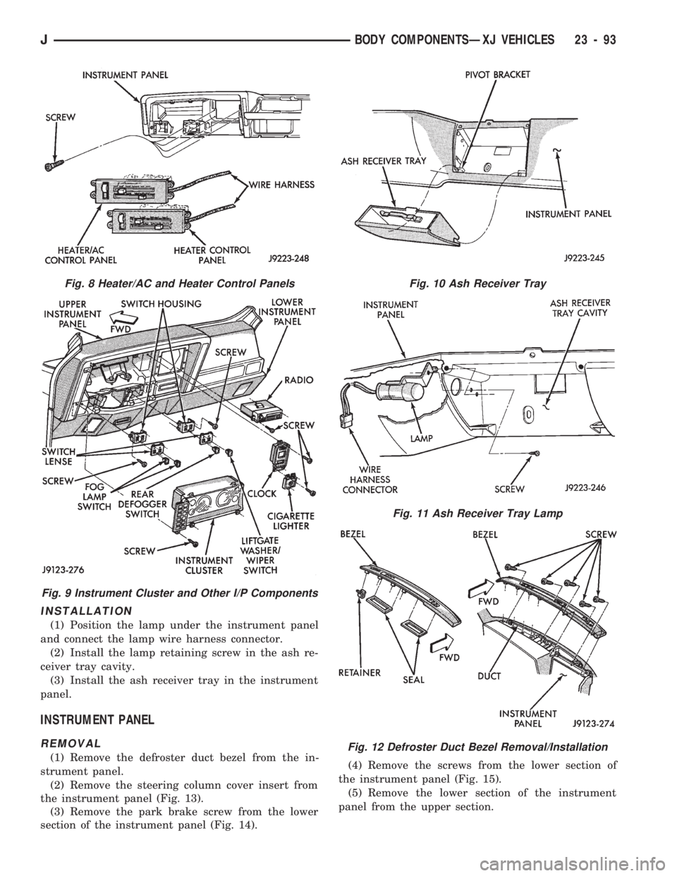
INSTALLATION
(1) Position the lamp under the instrument panel
and connect the lamp wire harness connector.
(2) Install the lamp retaining screw in the ash re-
ceiver tray cavity.
(3) Install the ash receiver tray in the instrument
panel.
INSTRUMENT PANEL
REMOVAL
(1) Remove the defroster duct bezel from the in-
strument panel.
(2) Remove the steering column cover insert from
the instrument panel (Fig. 13).
(3) Remove the park brake screw from the lower
section of the instrument panel (Fig. 14).(4) Remove the screws from the lower section of
the instrument panel (Fig. 15).
(5) Remove the lower section of the instrument
panel from the upper section.
Fig. 8 Heater/AC and Heater Control Panels
Fig. 9 Instrument Cluster and Other I/P Components
Fig. 10 Ash Receiver Tray
Fig. 11 Ash Receiver Tray Lamp
Fig. 12 Defroster Duct Bezel Removal/Installation
JBODY COMPONENTSÐXJ VEHICLES 23 - 93
Page 1645 of 1784
INTERIOR COMPONENTS
INDEX
page page
Carpet/Floor Mats....................... 198
Floor Consoles......................... 197
Front Shoulder Belts..................... 196
Glove Box............................. 194
Instrument Cluster and Gauge Housings...... 190
Instrument Cluster Bezel.................. 191Instrument Panel........................ 190
Instrument Panel Components.............. 191
Instrument Panel Service.................. 192
Rear Shoulder Belts..................... 196
Seats................................ 195
Sunvisors............................. 196
INSTRUMENT PANEL
SERVICE INFORMATION
The instrument panel is constructed of sheet metal
and is attached to cowl panel with screws. The in-
strument panel and defroster grille pad is attached
to the instrument panel with screws.
INSTRUMENT CLUSTER AND GAUGE HOUSINGS
REMOVAL
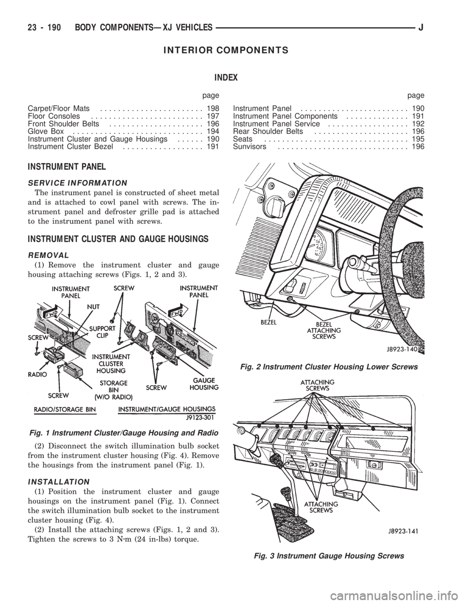
(1) Remove the instrument cluster and gauge
housing attaching screws (Figs. 1, 2 and 3).
(2) Disconnect the switch illumination bulb socket
from the instrument cluster housing (Fig. 4). Remove
the housings from the instrument panel (Fig. 1).
INSTALLATION
(1) Position the instrument cluster and gauge
housings on the instrument panel (Fig. 1). Connect
the switch illumination bulb socket to the instrument
cluster housing (Fig. 4).
(2) Install the attaching screws (Figs. 1, 2 and 3).
Tighten the screws to 3 Nzm (24 in-lbs) torque.
Fig. 2 Instrument Cluster Housing Lower Screws
Fig. 3 Instrument Gauge Housing Screws
Fig. 1 Instrument Cluster/Gauge Housing and Radio
23 - 190 BODY COMPONENTSÐXJ VEHICLESJ
Page 1646 of 1784
INSTRUMENT CLUSTER BEZEL
REMOVAL
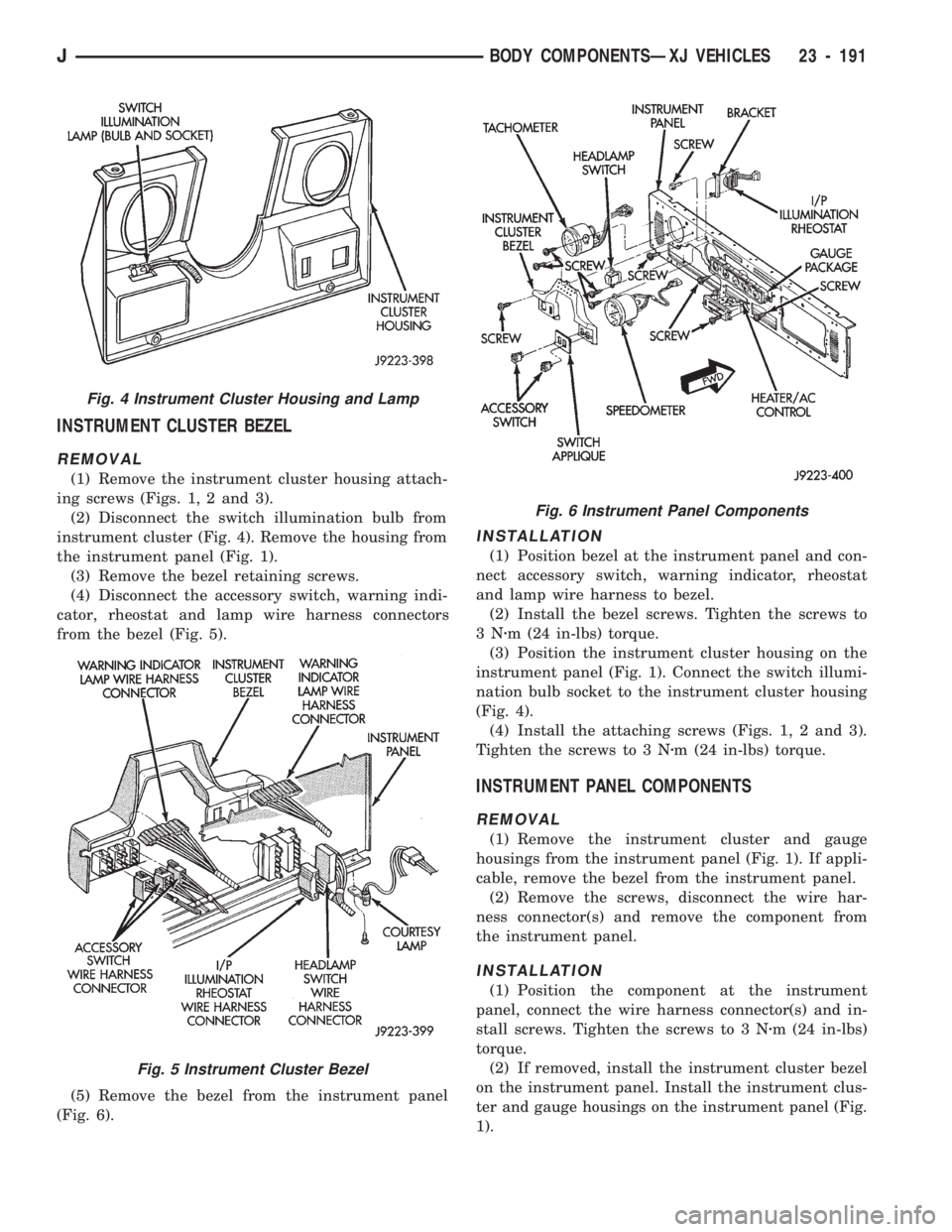
(1) Remove the instrument cluster housing attach-
ing screws (Figs. 1, 2 and 3).
(2) Disconnect the switch illumination bulb from
instrument cluster (Fig. 4). Remove the housing from
the instrument panel (Fig. 1).
(3) Remove the bezel retaining screws.
(4) Disconnect the accessory switch, warning indi-
cator, rheostat and lamp wire harness connectors
from the bezel (Fig. 5).
(5) Remove the bezel from the instrument panel
(Fig. 6).
INSTALLATION
(1) Position bezel at the instrument panel and con-
nect accessory switch, warning indicator, rheostat
and lamp wire harness to bezel.
(2) Install the bezel screws. Tighten the screws to
3Nzm (24 in-lbs) torque.
(3) Position the instrument cluster housing on the
instrument panel (Fig. 1). Connect the switch illumi-
nation bulb socket to the instrument cluster housing
(Fig. 4).
(4) Install the attaching screws (Figs. 1, 2 and 3).
Tighten the screws to 3 Nzm (24 in-lbs) torque.
INSTRUMENT PANEL COMPONENTS
REMOVAL
(1) Remove the instrument cluster and gauge
housings from the instrument panel (Fig. 1). If appli-
cable, remove the bezel from the instrument panel.
(2) Remove the screws, disconnect the wire har-
ness connector(s) and remove the component from
the instrument panel.
INSTALLATION
(1) Position the component at the instrument
panel, connect the wire harness connector(s) and in-
stall screws. Tighten the screws to 3 Nzm (24 in-lbs)
torque.
(2) If removed, install the instrument cluster bezel
on the instrument panel. Install the instrument clus-
ter and gauge housings on the instrument panel (Fig.
1).
Fig. 4 Instrument Cluster Housing and Lamp
Fig. 5 Instrument Cluster Bezel
Fig. 6 Instrument Panel Components
JBODY COMPONENTSÐXJ VEHICLES 23 - 191
Page 1647 of 1784
INSTRUMENT PANEL SERVICE
REMOVAL
(1) Disconnect the battery negative cable.
(2) For vehicles equipped with a soft top, discon-
nect the top from the windshield frame. If necessary,
refer to the top removal procedure.
(3) For vehicles equipped with a hard top, discon-
nect the top from the windshield frame. Loosen
screws, tilt the top rearward and support it away
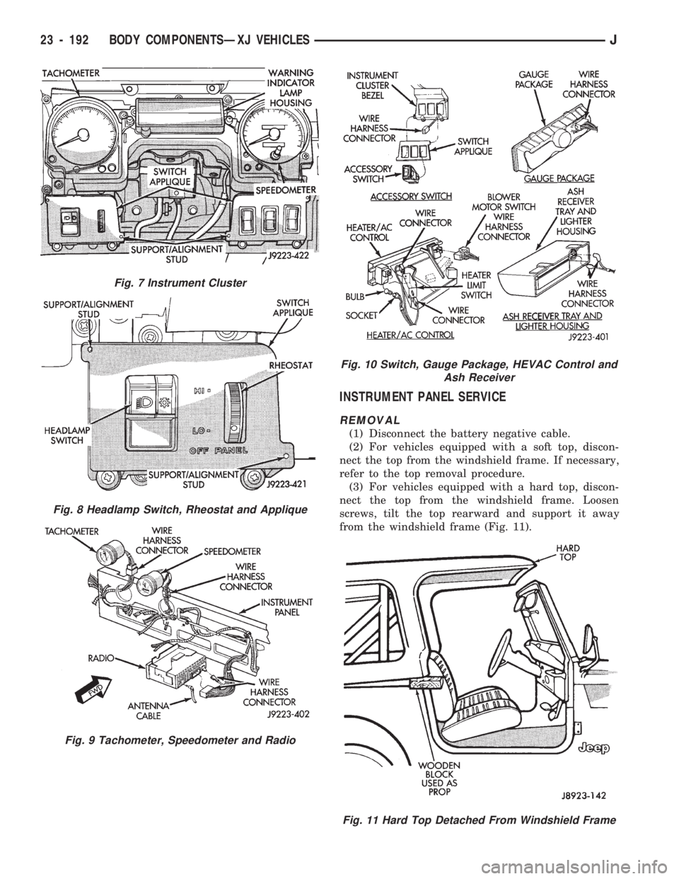
from the windshield frame (Fig. 11).
Fig. 7 Instrument Cluster
Fig. 8 Headlamp Switch, Rheostat and Applique
Fig. 9 Tachometer, Speedometer and Radio
Fig. 10 Switch, Gauge Package, HEVAC Control and
Ash Receiver
Fig. 11 Hard Top Detached From Windshield Frame
23 - 192 BODY COMPONENTSÐXJ VEHICLESJ
Page 1648 of 1784
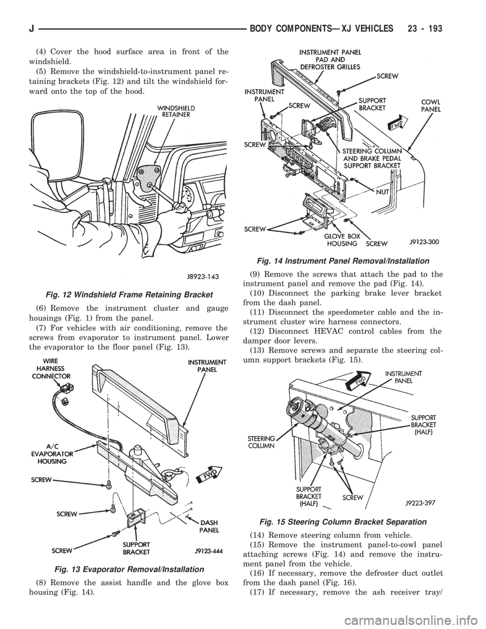
(4) Cover the hood surface area in front of the
windshield.
(5) Remove the windshield-to-instrument panel re-
taining brackets (Fig. 12) and tilt the windshield for-
ward onto the top of the hood.
(6) Remove the instrument cluster and gauge
housings (Fig. 1) from the panel.
(7) For vehicles with air conditioning, remove the
screws from evaporator to instrument panel. Lower
the evaporator to the floor panel (Fig. 13).
(8) Remove the assist handle and the glove box
housing (Fig. 14).(9) Remove the screws that attach the pad to the
instrument panel and remove the pad (Fig. 14).
(10) Disconnect the parking brake lever bracket
from the dash panel.
(11) Disconnect the speedometer cable and the in-
strument cluster wire harness connectors.
(12) Disconnect HEVAC control cables from the
damper door levers.
(13) Remove screws and separate the steering col-
umn support brackets (Fig. 15).
(14) Remove steering column from vehicle.
(15) Remove the instrument panel-to-cowl panel
attaching screws (Fig. 14) and remove the instru-
ment panel from the vehicle.
(16) If necessary, remove the defroster duct outlet
from the dash panel (Fig. 16).
(17) If necessary, remove the ash receiver tray/
Fig. 12 Windshield Frame Retaining Bracket
Fig. 13 Evaporator Removal/Installation
Fig. 14 Instrument Panel Removal/Installation
Fig. 15 Steering Column Bracket Separation
JBODY COMPONENTSÐXJ VEHICLES 23 - 193
Page 1649 of 1784
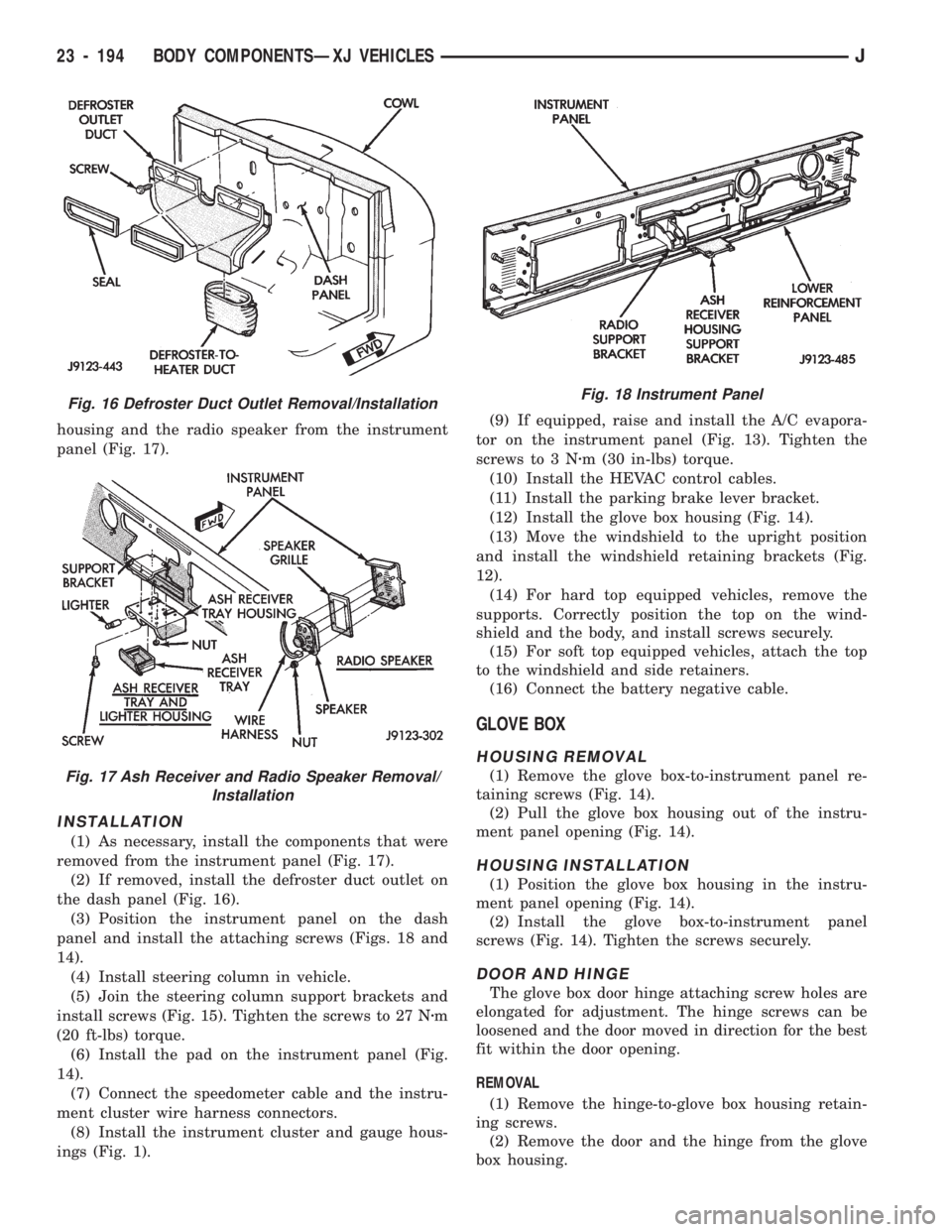
housing and the radio speaker from the instrument
panel (Fig. 17).
INSTALLATION
(1) As necessary, install the components that were
removed from the instrument panel (Fig. 17).
(2) If removed, install the defroster duct outlet on
the dash panel (Fig. 16).
(3) Position the instrument panel on the dash
panel and install the attaching screws (Figs. 18 and
14).
(4) Install steering column in vehicle.
(5) Join the steering column support brackets and
install screws (Fig. 15). Tighten the screws to 27 Nzm
(20 ft-lbs) torque.
(6) Install the pad on the instrument panel (Fig.
14).
(7) Connect the speedometer cable and the instru-
ment cluster wire harness connectors.
(8) Install the instrument cluster and gauge hous-
ings (Fig. 1).(9) If equipped, raise and install the A/C evapora-
tor on the instrument panel (Fig. 13). Tighten the
screws to 3 Nzm (30 in-lbs) torque.
(10) Install the HEVAC control cables.
(11) Install the parking brake lever bracket.
(12) Install the glove box housing (Fig. 14).
(13) Move the windshield to the upright position
and install the windshield retaining brackets (Fig.
12).
(14) For hard top equipped vehicles, remove the
supports. Correctly position the top on the wind-
shield and the body, and install screws securely.
(15) For soft top equipped vehicles, attach the top
to the windshield and side retainers.
(16) Connect the battery negative cable.
GLOVE BOX
HOUSING REMOVAL
(1) Remove the glove box-to-instrument panel re-
taining screws (Fig. 14).
(2) Pull the glove box housing out of the instru-
ment panel opening (Fig. 14).
HOUSING INSTALLATION
(1) Position the glove box housing in the instru-
ment panel opening (Fig. 14).
(2) Install the glove box-to-instrument panel
screws (Fig. 14). Tighten the screws securely.
DOOR AND HINGE
The glove box door hinge attaching screw holes are
elongated for adjustment. The hinge screws can be
loosened and the door moved in direction for the best
fit within the door opening.
REMOVAL
(1) Remove the hinge-to-glove box housing retain-
ing screws.
(2) Remove the door and the hinge from the glove
box housing.
Fig. 16 Defroster Duct Outlet Removal/Installation
Fig. 17 Ash Receiver and Radio Speaker Removal/
Installation
Fig. 18 Instrument Panel
23 - 194 BODY COMPONENTSÐXJ VEHICLESJ
Page 1702 of 1784
FRESH AIR VENTILATION
The fresh air ventilating system (Fig. 3) is oper-
ated by the air control lever. When the lever is
moved to VENT position, outside air from the cowl
intake flows into the heater housing. Incoming air is
directed into the vehicle interior through vent doors
in the housing.
A door in the intake duct controls air flow into the
duct. The door is operated by a vacuum motor. The
motor is controlled by a vacuum switch in the heater
control panel. The vent air doors are opened and
closed by a cable and linkage operated by the air
control lever. Fresh air intake occurs only when the
lever is in the VENT position.
HEATER CONTROL PANEL REPLACEMENT
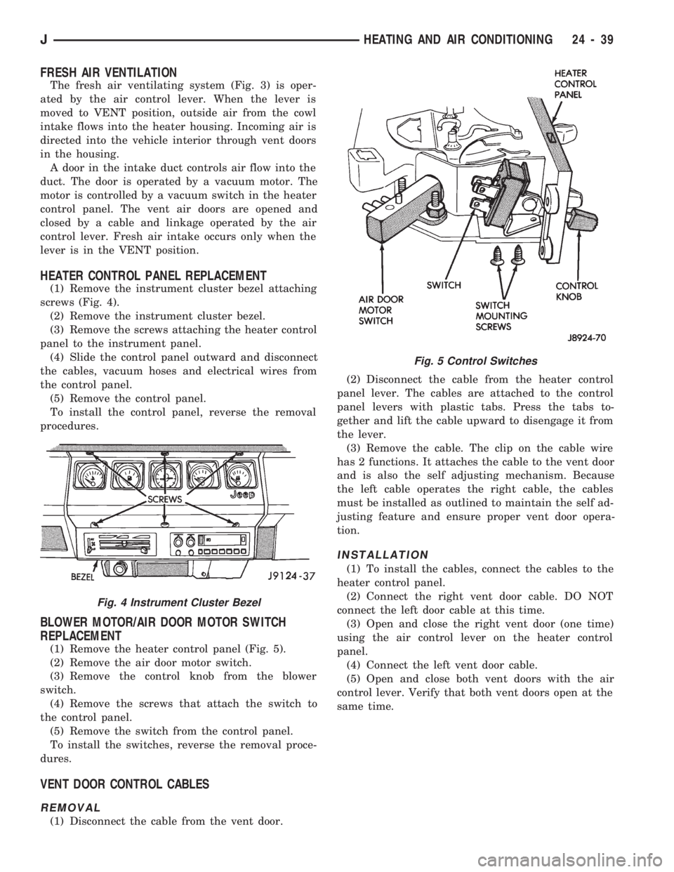
(1) Remove the instrument cluster bezel attaching
screws (Fig. 4).
(2) Remove the instrument cluster bezel.
(3) Remove the screws attaching the heater control
panel to the instrument panel.
(4) Slide the control panel outward and disconnect
the cables, vacuum hoses and electrical wires from
the control panel.
(5) Remove the control panel.
To install the control panel, reverse the removal
procedures.
BLOWER MOTOR/AIR DOOR MOTOR SWITCH
REPLACEMENT
(1) Remove the heater control panel (Fig. 5).
(2) Remove the air door motor switch.
(3) Remove the control knob from the blower
switch.
(4) Remove the screws that attach the switch to
the control panel.
(5) Remove the switch from the control panel.
To install the switches, reverse the removal proce-
dures.
VENT DOOR CONTROL CABLES
REMOVAL
(1) Disconnect the cable from the vent door.(2) Disconnect the cable from the heater control
panel lever. The cables are attached to the control
panel levers with plastic tabs. Press the tabs to-
gether and lift the cable upward to disengage it from
the lever.
(3) Remove the cable. The clip on the cable wire
has 2 functions. It attaches the cable to the vent door
and is also the self adjusting mechanism. Because
the left cable operates the right cable, the cables
must be installed as outlined to maintain the self ad-
justing feature and ensure proper vent door opera-
tion.
INSTALLATION
(1) To install the cables, connect the cables to the
heater control panel.
(2) Connect the right vent door cable. DO NOT
connect the left door cable at this time.
(3) Open and close the right vent door (one time)
using the air control lever on the heater control
panel.
(4) Connect the left vent door cable.
(5) Open and close both vent doors with the air
control lever. Verify that both vent doors open at the
same time.
Fig. 4 Instrument Cluster Bezel
Fig. 5 Control Switches
JHEATING AND AIR CONDITIONING 24 - 39
Page 1746 of 1784
ASSEMBLY REPLACEMENTÐYJ VEHICLES,
DRIVE AXLE; FRONT SUSPENSION AND
AXLE...............................2-21
ASSEMBLY REPLACEMENTÐYJ VEHICLES,
DRIVE AXLE; REAR SUSPENSION AND
AXLES..............................3-12
ASSEMBLY (SHORT BLOCK), SERVICE
ENGINE..............................9-4
ASSEMBLY TIPS, TRANSMISSION........21-146
ASSEMBLY, TRANSFER CASE......21-282,21-306
ASSEMBLYÐXJ VEHICLES, ENGINE....9-14,9-54
ASSEMBLYÐYJ VEHICLES, ENGINE....9-16,9-57
ASSEMBLY/INSTALLATION, PINION
GEAR; FRONT SUSPENSION AND AXLE....2-40
ASSEMBLY/INSTALLATION, PINION
GEAR; REAR SUSPENSION AND AXLES....3-22
ASSIST HANDLE, FULL-METAL DOOR.....23-175
ASSIST HANDLEÐXJ VEHICLES.........23-118
AUTO SHUT DOWN (ASD) RELAYÐPCM
OUTPUT............................14-24
AUTOMATIC BELT TENSIONERÐXJ
MODELS............................7-36
AUTOMATIC, PARK-LOCK CABLEÐ
CONSOLE SHIFT.....................19-45
AUTOMATIC SHUT DOWN (ASD) RELAY;
FUEL SYSTEM.......................14-54
AUTOMATIC SHUT DOWN (ASD) RELAY;
IGNITION SYSTEMS..........8D-1,8D-8,8D-20
AUTOMATIC SHUT DOWN (ASD) RELAY
TESTING...........................14-43
AUTOMATIC SHUT DOWN (ASD)
SENSEÐPCM INPUT..................14-19
AUTOMATIC TRANSMISSION..............0-23
AUTOMATIC TRANSMISSION, 30RH/
32RH..............................21-66
AUTOMATIC TRANSMISSION, AW-4.......21-156
AW-4 AUTOMATIC TRANSMISSION.......21-156
AW-4 BUSHING AND PISTON CLEARANCE . . 21-326
AW-4 CLUTCH AND BRAKE PACK
REQUIREMENTS....................21-328
AW-4 CLUTCH DISC AND PLATE
THICKNESS........................21-325
AW-4 GENERAL SPECIFICATIONS........21-324
AW-4 IN-VEHICLE SERVICE.............21-173
AW-4 OIL PUMP WEAR LIMITS..........21-325
AW-4 RETAINER AND PISTON
SPECIFICATIONS....................21-327
AW-4 TORQUE SPECIFICATIONS.........21-331
AW-4 TRANSMISSION DIAGNOSIS.......21-167
AW-4 TRANSMISSION OVERHAUL........21-192
AW-4 TRANSMISSION REMOVAL AND
INSTALLATION......................21-189
AW-4 VALVE AND SPRING
IDENTIFICATION....................21-330
AW-4 VALVE BODY CHECK BALL
DIMENSIONS.......................21-328
AX 15 MANUAL TRANSMISSION..........21-32
AX 15 MANUAL TRANSMISSION,
TORQUE SPECIFICATIONS.............21-320
AX 4/5 MANUAL TRANSMISSION..........21-1
AXLE (2WD), MODEL 30 AXLE AND TUBE . . . 2-20
AXLE 8 1/4 INCH, REAR.........3-29,3-44,3-50
AXLE ALIGNMENT, REAR..................3-8
AXLE AND TUBE AXLE (2WD), MODEL 30 . . . 2-20
AXLE ASSEMBLY REPLACEMENTÐXJ
VEHICLES, DRIVE; FRONT SUSPENSION
AND AXLE...........................2-21
AXLE ASSEMBLY REPLACEMENTÐ
XJ VEHICLES, DRIVE; REAR SUSPENSION
AND AXLES......................3-11,3-30
AXLE ASSEMBLY REPLACEMENTÐ
YJ VEHICLES, DRIVE; FRONT SUSPENSION
AND AXLE...........................2-21
AXLE ASSEMBLY REPLACEMENTÐ
YJ VEHICLES, DRIVE; REAR SUSPENSION
AND AXLES..........................3-12
AXLE BUSHING REPLACEMENT........2-11,2-32
AXLE, FRONT DRIVE.....................2-3
AXLE, MODEL 30 FRONT.............2-46,2-47
AXLE MODEL 35, REAR........3-11, 3-28, 3-50
AXLE NOISE/VIBRATION DIAGNOSIS;
FRONT SUSPENSION AND AXLE
..........2-16
AXLE NOISE/VIBRATION DIAGNOSIS;
REAR SUSPENSION AND AXLES
..........3-7
AXLE SHAFT
...........................3-14
AXLE SHAFTÐCARDAN U-JOINT
...........2-25AXLE SHAFT, HUB BEARING..............2-24
AXLE SHAFT OIL SEAL REPLACEMENT,
INNER..............................2-33
AXLE SHAFT SEAL AND BEARING..........3-15
AXLE SHAFT, SEAL AND BEARING
SERVICE............................3-31
AXLE SPECIFICATIONS; FRONT
SUSPENSION AND AXLE................2-46
AXLE SPECIFICATIONS; REAR
SUSPENSION AND AXLES...........3-28,3-44
AXLEÐYJ VEHICLES, VACUUM
DISCONNECT.........................2-26
AXLES................................3-1
AXLES, FRONT AND REAR................0-26
AXLE/SHIFT MOTOR DIAGNOSIS
DISCONNECT.....................2-28,2-27
BACKLASH AND CONTACT PATTERN
ANALYSIS; FRONT SUSPENSION AND AXLE . 2-44
BACKLASH AND CONTACT PATTERN
ANALYSIS; REAR SUSPENSION AND
AXLES..............................3-25
BACK-UP/REAR TURN SIGNAL/TAIL
LAMP BULB REPLACEMENT.............8L-9
BALANCE, TIRE AND WHEEL..............22-6
BALL DIMENSIONS, AW-4 VALVE BODY
CHECK............................21-328
BALL POWER STEERING GEAR,
RECIRCULATING.....................19-19
BALL STUD REPLACEMENT, LIFTGATE
SUPPORT ROD......................23-70
BALL STUDS, STEERING KNUCKLE.........2-30
BALL STUDS, STEERING LINKAGE.........0-30
BAND ADJUSTMENT, FRONT.............21-99
BAND ADJUSTMENT, REAR..............21-99
BAND ADJUSTMENTS, SPECIFICATIONS....21-66
BAND OVERHAUL, FRONT SERVO........21-136
BAND OVERHAUL, REAR SERVO.........21-136
BANKS, FUSE CHARTS AND RELAY........8W-8
BAR REPLACEMENT, SOUND..............8F-7
BAR, SPORT.........................23-171
BAR, STABILIZER...................2-10,2-14
BAR, TRACK; FRONT SUSPENSION AND
AXLE...........................2-10,2-13
BAR, TRACK; REAR SUSPENSION AND
AXLES...............................3-6
BARÐXJ VEHICLES, STABILIZER...........3-4
BASECOAT/CLEARCOAT................23-202
BASE/COLOR COAT...................23-201
BATTERY.............................0-18
BATTERY CHARGING....................8A-5
BATTERY CHARGING TIME TABLE..........8A-5
BATTERY CLASSIFICATIONS AND
RATINGS............................8A-8
BATTERY CLASSIFICATIONS AND
RATINGSÐLEFT HAND DRIVE..........8B-10
BATTERY CLASSIFICATIONS AND
RATINGSÐRIGHT HAND DRIVE.........8B-10
BATTERY DIAGNOSTICS CHART...........8A-7
BATTERY INDICATOR (BASE CLUSTER
ONLY), OPERATIONAL CHECK...........8A-14
BATTERY LOAD TEST....................8A-4
BATTERY MAINTENANCE.................8B-1
BATTERY OPEN CIRCUIT VOLTAGE.........8A-4
BATTERY OPEN CIRCUIT VOLTAGE TEST....8A-3
BATTERY REPLACEMENTÐLEFT HAND
DRIVE..............................8B-1
BATTERY REPLACEMENTÐRIGHT HAND
DRIVE..............................8B-2
BATTERY SERVICE PROCEDURES..........8B-1
BATTERY TEST PROCEDURES.............8A-2
BATTERY TESTING GENERAL
INFORMATION........................8A-3
BATTERY TORQUE SPECIFICATIONS.......8B-10
BATTERY TRAY..................23-13,23-140
BATTERY VOLTAGEÐPCM INPUT.........14-19
BATTERY/STARTING/CHARGING
SYSTEMS DIAGNOSTICS...............8A-1
BEAM ADJUSTMENT, FOG LAMP..........8L-12
BEAM ADJUSTMENT, HEADLAMP..........8L-3
BEARING AND AXLE SHAFT, HUB..........2-24
BEARING, AXLE SHAFT SEAL
..............3-15
BEARING FITTING CHART, CONNECTING
ROD
............................9-36,9-76
BEARING FITTING CHART, MAIN
.......9-43,9-83
BEARING LUBRICANTS, CHASSIS
COMPONENT AND WHEEL
..............0-30BEARING NOISE, GEAR AND; FRONT
SUSPENSION AND AXLE................2-16
BEARING NOISE, GEAR AND; REAR
SUSPENSION AND AXLES................3-7
BEARING REPLACEMENT, PILOT...........6-11
BEARING REPLACEMENT, PITMAN
SHAFT SEALS.......................19-32
BEARING REPLACEMENT, RELEASE.........6-11
BEARING SERVICE, AXLE SHAFT, SEAL......3-31
BEARINGS, CRANKSHAFT MAIN.......9-40,9-80
BEARINGS, FRONT WHEEL...............0-31
BELT, ACCESSORY DRIVE................0-20
BELT DIAGNOSIS.......................7-31
BELT DIAGNOSIS, SERPENTINE DRIVE......7-32
BELT INDICATOR, SEAT..................8E-4
BELT REMINDER LAMP, SEAT............8E-16
BELT SCHEMATICS......................7-34
BELT SERVICEÐEXCEPT RIGHT HAND
DRIVE..............................7-34
BELT SERVICEÐWITH RIGHT HAND
DRIVE..............................7-35
BELT TENSION........................8B-10
BELT TENSION, DRIVE...................7-38
BELT TENSIONÐEXCEPT RIGHT HAND
DRIVE (RHD).........................7-33
BELT TENSIONÐRIGHT HAND DRIVE (RHD) . . 7-34
BELT TENSION SPECIFICATIONS...........7-34
BELT TENSIONERÐXJ MODELS,
AUTOMATIC..........................7-36
BELT/BUCKLEÐXJ VEHICLES, FRONT
SHOULDER........................23-119
BELT/BUCKLEÐXJ VEHICLES,
REAR SHOULDER/LAP...............23-120
BELTS, ENGINE ACCESSORY DRIVE........7-31
BELTS, FRONT SHOULDER..............23-196
BELTS, REAR SHOULDER...............23-196
BENCH, GEAR ADJUSTMENTS............19-42
BEZEL, INSTRUMENT CLUSTER.....23-91,23-191
BEZEL REPLACEMENT, INDICATOR........8E-17
BLADE REPLACEMENT, FRONT WIPER......8K-8
BLEEDINGÐBRAKE FLUID AND LEVELÐ
BRAKELINES AND HOSES, BRAKE........5-13
BLEEDINGÐWITH ABS BRAKES, BRAKE.....5-14
BLEEDINGÐWITH STANDARD BRAKES,
BRAKE..............................5-13
BLOCK, CYLINDER..................9-45,9-85
BLOCK HEATER, ENGINE.................7-37
BLOCKSÐTWO-DOOR VEHICLES, FRONT
DOOR SPACER......................23-60
BLOWER CONTROLSÐXJ VEHICLES.......24-14
BLOWER MOTOR, A/C..................24-43
BLOWER MOTOR (HEATING).............24-40
BLOWER MOTOR RESISTORS
REPLACEMENT......................24-35
BLOWER MOTOR/AIR DOOR MOTOR
SWITCH REPLACEMENT...............24-39
BLOWER MOTOR/FAN REPLACEMENT......24-26
BODY...............................13-18
BODY ASSEMBLY AND ADJUSTMENT,
VALVE ............................21-144
BODY CHECK BALL DIMENSIONS, AW-4
VALVE ............................21-328
BODY CODE LETTERS, JEEP...............5-2
BODY COLORS, EXTERIOR..............23-204
BODY COMPONENTS....................0-34
BODY COMPONENTS, CHASSIS............0-30
BODY COMPONENTSÐREFINISHING......23-200
BODY COMPONENTSÐYJ VEHICLES......23-132
BODY DISASSEMBLY AND INSPECTION,
VALVE
............................21-138
BODY EXTENSION PANELS AND
FASCIASÐYJ RENEGADE VEHICLES
.....23-147
BODY INSTALLATION, TRANSMISSION
VALVE
............................21-177
BODY INSTALLATION, VALVE
............21-101
BODY LUBRICANT SPECIFICATIONS
........0-35
BODY OVERHAUL, TRANSMISSION
VALVE
............................21-240
BODY REMOVAL, TRANSMISSION
VALVE
............................21-176
BODY REMOVAL, VALVE
...............21-100
BODY SERVICE INFORMATION, GENERAL
....23-1
BODY SERVICE, VALVE
................21-100
BODY SIDE MOULDING/CLADDING
........23-19
BODY SIDE STEP MOULDING
...........23-145
2 INDEXJ
Description Group-Page Description Group-Page Description Group-Page