1994 JEEP CHEROKEE lock
[x] Cancel search: lockPage 1250 of 1784
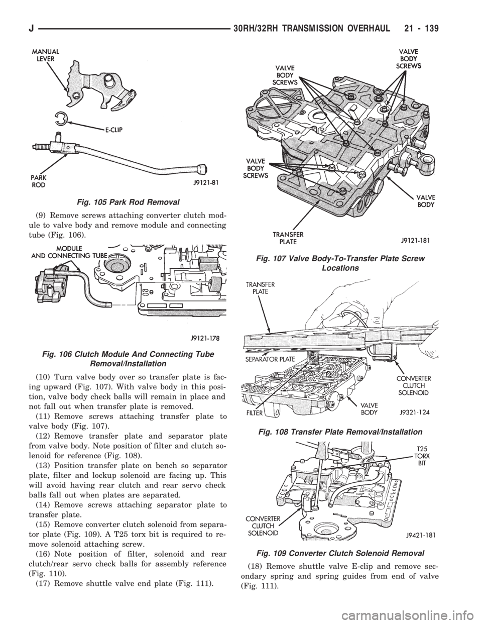
(9) Remove screws attaching converter clutch mod-
ule to valve body and remove module and connecting
tube (Fig. 106).
(10) Turn valve body over so transfer plate is fac-
ing upward (Fig. 107). With valve body in this posi-
tion, valve body check balls will remain in place and
not fall out when transfer plate is removed.
(11) Remove screws attaching transfer plate to
valve body (Fig. 107).
(12) Remove transfer plate and separator plate
from valve body. Note position of filter and clutch so-
lenoid for reference (Fig. 108).
(13) Position transfer plate on bench so separator
plate, filter and lockup solenoid are facing up. This
will avoid having rear clutch and rear servo check
balls fall out when plates are separated.
(14) Remove screws attaching separator plate to
transfer plate.
(15) Remove converter clutch solenoid from separa-
tor plate (Fig. 109). A T25 torx bit is required to re-
move solenoid attaching screw.
(16) Note position of filter, solenoid and rear
clutch/rear servo check balls for assembly reference
(Fig. 110).
(17) Remove shuttle valve end plate (Fig. 111).(18) Remove shuttle valve E-clip and remove sec-
ondary spring and spring guides from end of valve
(Fig. 111).
Fig. 105 Park Rod Removal
Fig. 106 Clutch Module And Connecting Tube
Removal/Installation
Fig. 107 Valve Body-To-Transfer Plate Screw
Locations
Fig. 108 Transfer Plate Removal/Installation
Fig. 109 Converter Clutch Solenoid Removal
J30RH/32RH TRANSMISSION OVERHAUL 21 - 139
Page 1252 of 1784
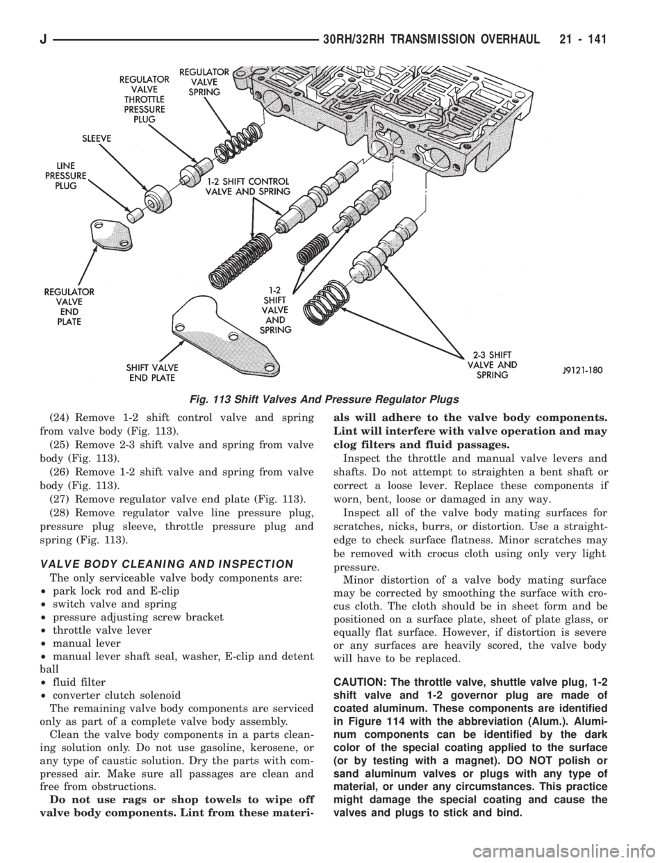
(24) Remove 1-2 shift control valve and spring
from valve body (Fig. 113).
(25) Remove 2-3 shift valve and spring from valve
body (Fig. 113).
(26) Remove 1-2 shift valve and spring from valve
body (Fig. 113).
(27) Remove regulator valve end plate (Fig. 113).
(28) Remove regulator valve line pressure plug,
pressure plug sleeve, throttle pressure plug and
spring (Fig. 113).
VALVE BODY CLEANING AND INSPECTION
The only serviceable valve body components are:
²park lock rod and E-clip
²switch valve and spring
²pressure adjusting screw bracket
²throttle valve lever
²manual lever
²manual lever shaft seal, washer, E-clip and detent
ball
²fluid filter
²converter clutch solenoid
The remaining valve body components are serviced
only as part of a complete valve body assembly.
Clean the valve body components in a parts clean-
ing solution only. Do not use gasoline, kerosene, or
any type of caustic solution. Dry the parts with com-
pressed air. Make sure all passages are clean and
free from obstructions.
Do not use rags or shop towels to wipe off
valve body components. Lint from these materi-als will adhere to the valve body components.
Lint will interfere with valve operation and may
clog filters and fluid passages.
Inspect the throttle and manual valve levers and
shafts. Do not attempt to straighten a bent shaft or
correct a loose lever. Replace these components if
worn, bent, loose or damaged in any way.
Inspect all of the valve body mating surfaces for
scratches, nicks, burrs, or distortion. Use a straight-
edge to check surface flatness. Minor scratches may
be removed with crocus cloth using only very light
pressure.
Minor distortion of a valve body mating surface
may be corrected by smoothing the surface with cro-
cus cloth. The cloth should be in sheet form and be
positioned on a surface plate, sheet of plate glass, or
equally flat surface. However, if distortion is severe
or any surfaces are heavily scored, the valve body
will have to be replaced.
CAUTION: The throttle valve, shuttle valve plug, 1-2
shift valve and 1-2 governor plug are made of
coated aluminum. These components are identified
in Figure 114 with the abbreviation (Alum.). Alumi-
num components can be identified by the dark
color of the special coating applied to the surface
(or by testing with a magnet). DO NOT polish or
sand aluminum valves or plugs with any type of
material, or under any circumstances. This practice
might damage the special coating and cause the
valves and plugs to stick and bind.
Fig. 113 Shift Valves And Pressure Regulator Plugs
J30RH/32RH TRANSMISSION OVERHAUL 21 - 141
Page 1257 of 1784
rect sequence. The correct sequence is line pressure
adjustment first and throttle pressure adjustment
last.
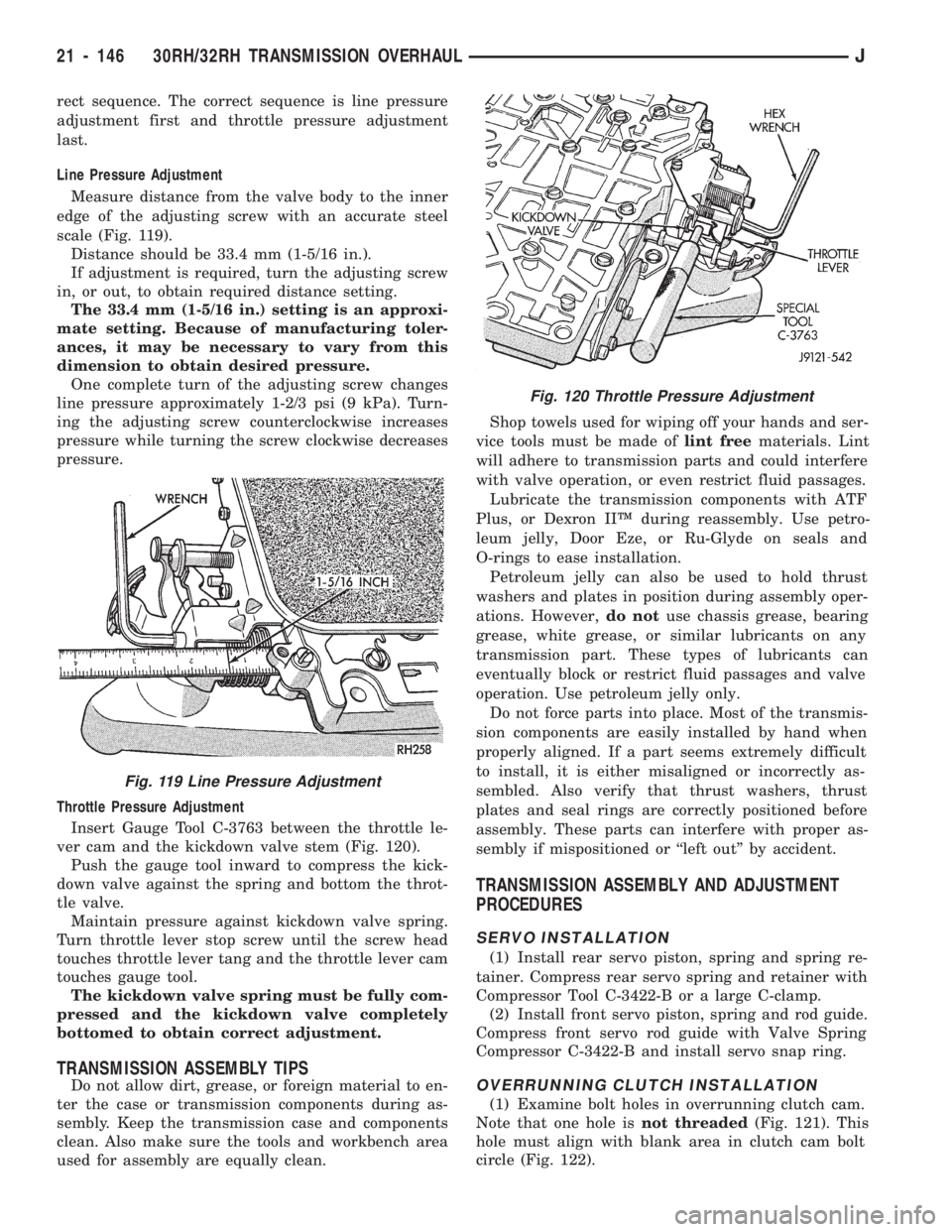
Line Pressure Adjustment
Measure distance from the valve body to the inner
edge of the adjusting screw with an accurate steel
scale (Fig. 119).
Distance should be 33.4 mm (1-5/16 in.).
If adjustment is required, turn the adjusting screw
in, or out, to obtain required distance setting.
The 33.4 mm (1-5/16 in.) setting is an approxi-
mate setting. Because of manufacturing toler-
ances, it may be necessary to vary from this
dimension to obtain desired pressure.
One complete turn of the adjusting screw changes
line pressure approximately 1-2/3 psi (9 kPa). Turn-
ing the adjusting screw counterclockwise increases
pressure while turning the screw clockwise decreases
pressure.
Throttle Pressure Adjustment
Insert Gauge Tool C-3763 between the throttle le-
ver cam and the kickdown valve stem (Fig. 120).
Push the gauge tool inward to compress the kick-
down valve against the spring and bottom the throt-
tle valve.
Maintain pressure against kickdown valve spring.
Turn throttle lever stop screw until the screw head
touches throttle lever tang and the throttle lever cam
touches gauge tool.
The kickdown valve spring must be fully com-
pressed and the kickdown valve completely
bottomed to obtain correct adjustment.
TRANSMISSION ASSEMBLY TIPS
Do not allow dirt, grease, or foreign material to en-
ter the case or transmission components during as-
sembly. Keep the transmission case and components
clean. Also make sure the tools and workbench area
used for assembly are equally clean.Shop towels used for wiping off your hands and ser-
vice tools must be made oflint freematerials. Lint
will adhere to transmission parts and could interfere
with valve operation, or even restrict fluid passages.
Lubricate the transmission components with ATF
Plus, or Dexron IIŸ during reassembly. Use petro-
leum jelly, Door Eze, or Ru-Glyde on seals and
O-rings to ease installation.
Petroleum jelly can also be used to hold thrust
washers and plates in position during assembly oper-
ations. However,do notuse chassis grease, bearing
grease, white grease, or similar lubricants on any
transmission part. These types of lubricants can
eventually block or restrict fluid passages and valve
operation. Use petroleum jelly only.
Do not force parts into place. Most of the transmis-
sion components are easily installed by hand when
properly aligned. If a part seems extremely difficult
to install, it is either misaligned or incorrectly as-
sembled. Also verify that thrust washers, thrust
plates and seal rings are correctly positioned before
assembly. These parts can interfere with proper as-
sembly if mispositioned or ``left out'' by accident.
TRANSMISSION ASSEMBLY AND ADJUSTMENT
PROCEDURES
SERVO INSTALLATION
(1) Install rear servo piston, spring and spring re-
tainer. Compress rear servo spring and retainer with
Compressor Tool C-3422-B or a large C-clamp.
(2) Install front servo piston, spring and rod guide.
Compress front servo rod guide with Valve Spring
Compressor C-3422-B and install servo snap ring.
OVERRUNNING CLUTCH INSTALLATION
(1) Examine bolt holes in overrunning clutch cam.
Note that one hole isnot threaded(Fig. 121). This
hole must align with blank area in clutch cam bolt
circle (Fig. 122).
Fig. 120 Throttle Pressure Adjustment
Fig. 119 Line Pressure Adjustment
21 - 146 30RH/32RH TRANSMISSION OVERHAULJ
Page 1258 of 1784
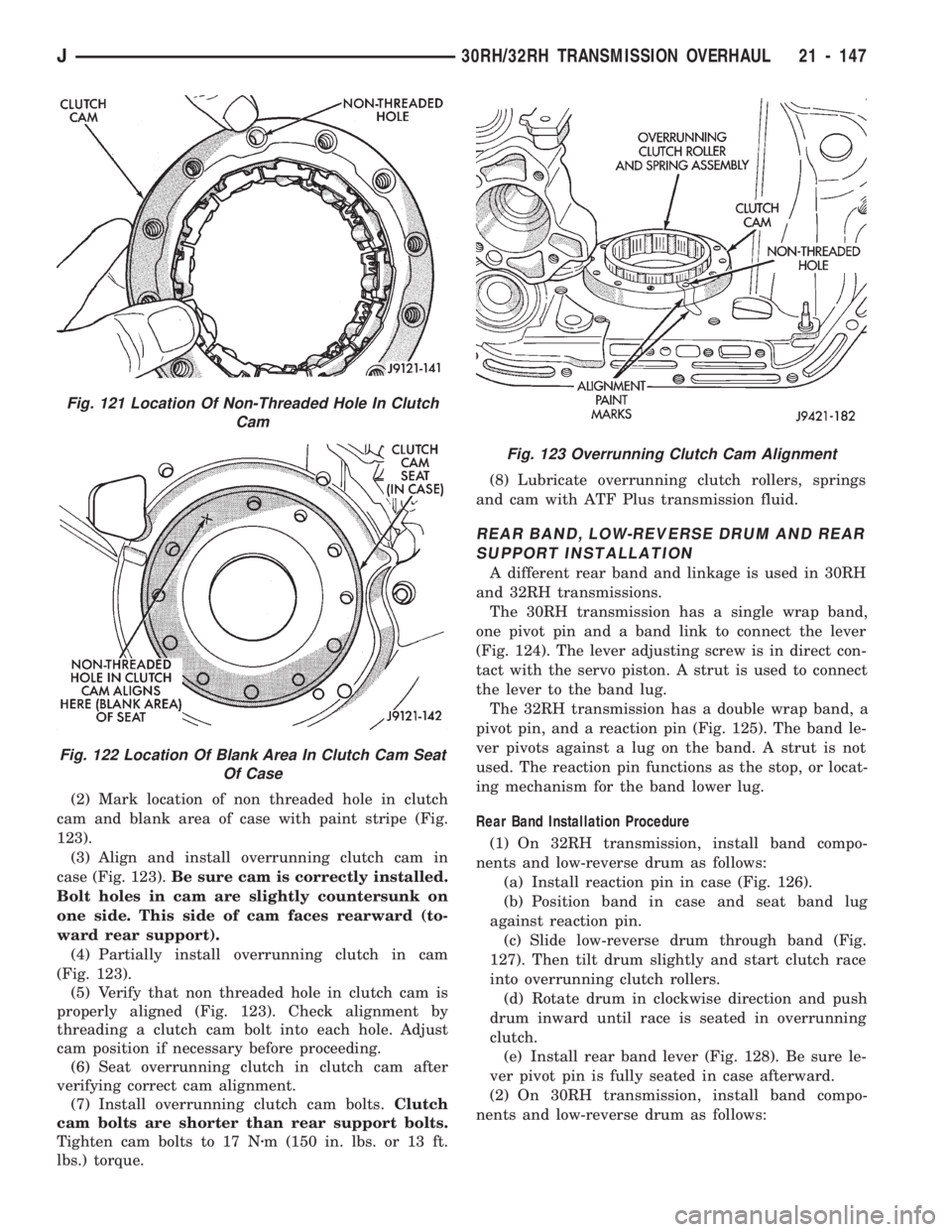
(2) Mark location of non threaded hole in clutch
cam and blank area of case with paint stripe (Fig.
123).
(3) Align and install overrunning clutch cam in
case (Fig. 123).Be sure cam is correctly installed.
Bolt holes in cam are slightly countersunk on
one side. This side of cam faces rearward (to-
ward rear support).
(4) Partially install overrunning clutch in cam
(Fig. 123).
(5) Verify that non threaded hole in clutch cam is
properly aligned (Fig. 123). Check alignment by
threading a clutch cam bolt into each hole. Adjust
cam position if necessary before proceeding.
(6) Seat overrunning clutch in clutch cam after
verifying correct cam alignment.
(7) Install overrunning clutch cam bolts.Clutch
cam bolts are shorter than rear support bolts.
Tighten cam bolts to 17 Nzm (150 in. lbs. or 13 ft.
lbs.) torque.(8) Lubricate overrunning clutch rollers, springs
and cam with ATF Plus transmission fluid.
REAR BAND, LOW-REVERSE DRUM AND REAR
SUPPORT INSTALLATION
A different rear band and linkage is used in 30RH
and 32RH transmissions.
The 30RH transmission has a single wrap band,
one pivot pin and a band link to connect the lever
(Fig. 124). The lever adjusting screw is in direct con-
tact with the servo piston. A strut is used to connect
the lever to the band lug.
The 32RH transmission has a double wrap band, a
pivot pin, and a reaction pin (Fig. 125). The band le-
ver pivots against a lug on the band. A strut is not
used. The reaction pin functions as the stop, or locat-
ing mechanism for the band lower lug.
Rear Band Installation Procedure
(1) On 32RH transmission, install band compo-
nents and low-reverse drum as follows:
(a) Install reaction pin in case (Fig. 126).
(b) Position band in case and seat band lug
against reaction pin.
(c) Slide low-reverse drum through band (Fig.
127). Then tilt drum slightly and start clutch race
into overrunning clutch rollers.
(d) Rotate drum in clockwise direction and push
drum inward until race is seated in overrunning
clutch.
(e) Install rear band lever (Fig. 128). Be sure le-
ver pivot pin is fully seated in case afterward.
(2) On 30RH transmission, install band compo-
nents and low-reverse drum as follows:
Fig. 123 Overrunning Clutch Cam Alignment
Fig. 121 Location Of Non-Threaded Hole In Clutch
Cam
Fig. 122 Location Of Blank Area In Clutch Cam Seat
Of Case
J30RH/32RH TRANSMISSION OVERHAUL 21 - 147
Page 1259 of 1784
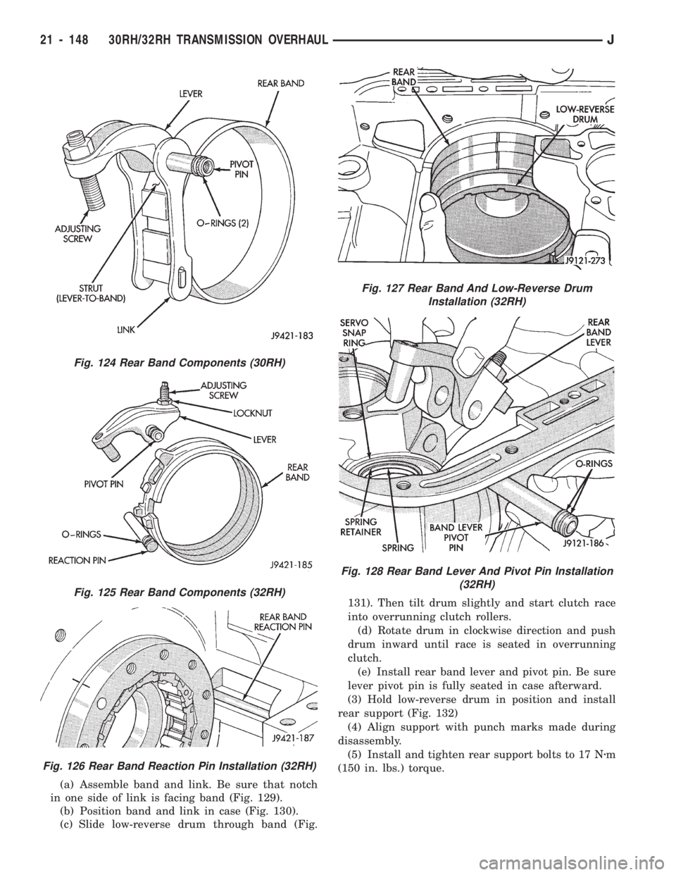
(a) Assemble band and link. Be sure that notch
in one side of link is facing band (Fig. 129).
(b) Position band and link in case (Fig. 130).
(c) Slide low-reverse drum through band (Fig.131). Then tilt drum slightly and start clutch race
into overrunning clutch rollers.
(d) Rotate drum in clockwise direction and push
drum inward until race is seated in overrunning
clutch.
(e) Install rear band lever and pivot pin. Be sure
lever pivot pin is fully seated in case afterward.
(3) Hold low-reverse drum in position and install
rear support (Fig. 132)
(4) Align support with punch marks made during
disassembly.
(5) Install and tighten rear support bolts to 17 Nzm
(150 in. lbs.) torque.
Fig. 124 Rear Band Components (30RH)
Fig. 125 Rear Band Components (32RH)
Fig. 126 Rear Band Reaction Pin Installation (32RH)
Fig. 127 Rear Band And Low-Reverse Drum
Installation (32RH)
Fig. 128 Rear Band Lever And Pivot Pin Installation
(32RH)
21 - 148 30RH/32RH TRANSMISSION OVERHAULJ
Page 1263 of 1784
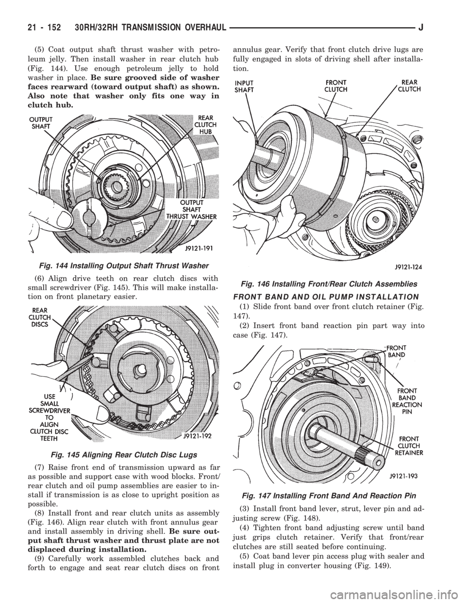
(5) Coat output shaft thrust washer with petro-
leum jelly. Then install washer in rear clutch hub
(Fig. 144). Use enough petroleum jelly to hold
washer in place.Be sure grooved side of washer
faces rearward (toward output shaft) as shown.
Also note that washer only fits one way in
clutch hub.
(6) Align drive teeth on rear clutch discs with
small screwdriver (Fig. 145). This will make installa-
tion on front planetary easier.
(7) Raise front end of transmission upward as far
as possible and support case with wood blocks. Front/
rear clutch and oil pump assemblies are easier to in-
stall if transmission is as close to upright position as
possible.
(8) Install front and rear clutch units as assembly
(Fig. 146). Align rear clutch with front annulus gear
and install assembly in driving shell.Be sure out-
put shaft thrust washer and thrust plate are not
displaced during installation.
(9) Carefully work assembled clutches back and
forth to engage and seat rear clutch discs on frontannulus gear. Verify that front clutch drive lugs are
fully engaged in slots of driving shell after installa-
tion.
FRONT BAND AND OIL PUMP INSTALLATION
(1) Slide front band over front clutch retainer (Fig.
147).
(2) Insert front band reaction pin part way into
case (Fig. 147).
(3) Install front band lever, strut, lever pin and ad-
justing screw (Fig. 148).
(4) Tighten front band adjusting screw until band
just grips clutch retainer. Verify that front/rear
clutches are still seated before continuing.
(5) Coat band lever pin access plug with sealer and
install plug in converter housing (Fig. 149).
Fig. 144 Installing Output Shaft Thrust Washer
Fig. 145 Aligning Rear Clutch Disc Lugs
Fig. 146 Installing Front/Rear Clutch Assemblies
Fig. 147 Installing Front Band And Reaction Pin
21 - 152 30RH/32RH TRANSMISSION OVERHAULJ
Page 1265 of 1784
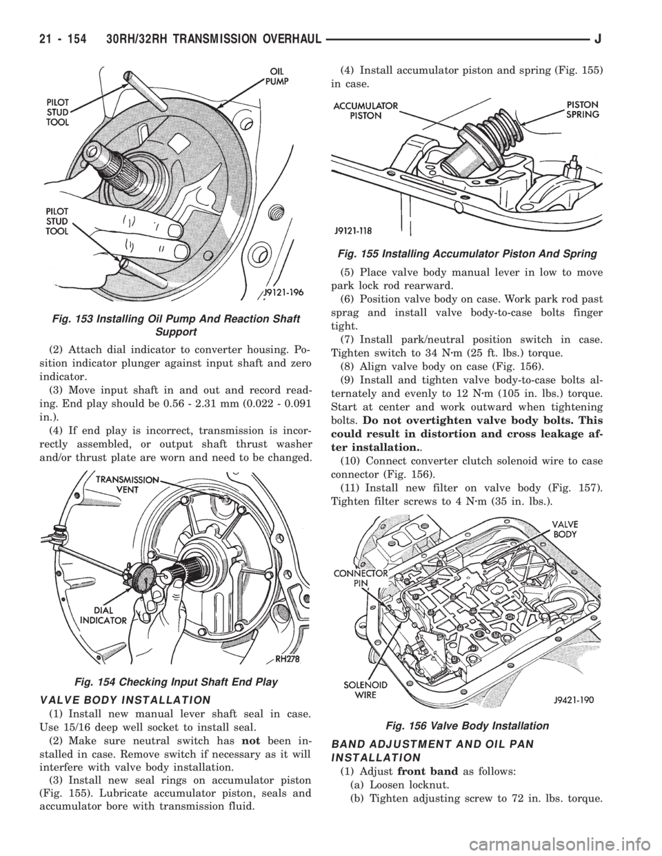
(2) Attach dial indicator to converter housing. Po-
sition indicator plunger against input shaft and zero
indicator.
(3) Move input shaft in and out and record read-
ing. End play should be 0.56 - 2.31 mm (0.022 - 0.091
in.).
(4) If end play is incorrect, transmission is incor-
rectly assembled, or output shaft thrust washer
and/or thrust plate are worn and need to be changed.
VALVE BODY INSTALLATION
(1) Install new manual lever shaft seal in case.
Use 15/16 deep well socket to install seal.
(2) Make sure neutral switch hasnotbeen in-
stalled in case. Remove switch if necessary as it will
interfere with valve body installation.
(3) Install new seal rings on accumulator piston
(Fig. 155). Lubricate accumulator piston, seals and
accumulator bore with transmission fluid.(4) Install accumulator piston and spring (Fig. 155)
in case.
(5) Place valve body manual lever in low to move
park lock rod rearward.
(6) Position valve body on case. Work park rod past
sprag and install valve body-to-case bolts finger
tight.
(7) Install park/neutral position switch in case.
Tighten switch to 34 Nzm (25 ft. lbs.) torque.
(8) Align valve body on case (Fig. 156).
(9) Install and tighten valve body-to-case bolts al-
ternately and evenly to 12 Nzm (105 in. lbs.) torque.
Start at center and work outward when tightening
bolts.Do not overtighten valve body bolts. This
could result in distortion and cross leakage af-
ter installation..
(10) Connect converter clutch solenoid wire to case
connector (Fig. 156).
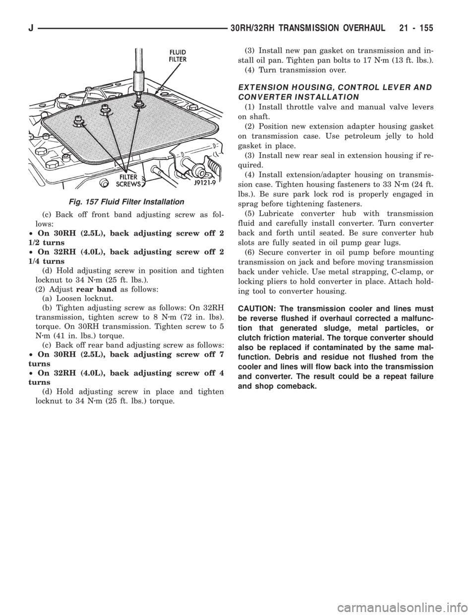
(11) Install new filter on valve body (Fig. 157).
Tighten filter screws to 4 Nzm (35 in. lbs.).
BAND ADJUSTMENT AND OIL PAN
INSTALLATION
(1) Adjustfront bandas follows:
(a) Loosen locknut.
(b) Tighten adjusting screw to 72 in. lbs. torque.
Fig. 153 Installing Oil Pump And Reaction Shaft
Support
Fig. 154 Checking Input Shaft End Play
Fig. 155 Installing Accumulator Piston And Spring
Fig. 156 Valve Body Installation
21 - 154 30RH/32RH TRANSMISSION OVERHAULJ
Page 1266 of 1784
(c) Back off front band adjusting screw as fol-
lows:
²On 30RH (2.5L), back adjusting screw off 2
1/2 turns
²On 32RH (4.0L), back adjusting screw off 2
1/4 turns
(d) Hold adjusting screw in position and tighten
locknut to 34 Nzm (25 ft. lbs.).
(2) Adjustrear bandas follows:
(a) Loosen locknut.
(b) Tighten adjusting screw as follows: On 32RH
transmission, tighten screw to 8 Nzm (72 in. lbs).
torque. On 30RH transmission. Tighten screw to 5
Nzm (41 in. lbs.) torque.
(c) Back off rear band adjusting screw as follows:
²On 30RH (2.5L), back adjusting screw off 7
turns
²On 32RH (4.0L), back adjusting screw off 4
turns
(d) Hold adjusting screw in place and tighten
locknut to 34 Nzm (25 ft. lbs.) torque.(3) Install new pan gasket on transmission and in-
stall oil pan. Tighten pan bolts to 17 Nzm (13 ft. lbs.).
(4) Turn transmission over.
EXTENSION HOUSING, CONTROL LEVER AND
CONVERTER INSTALLATION
(1) Install throttle valve and manual valve levers
on shaft.
(2) Position new extension adapter housing gasket
on transmission case. Use petroleum jelly to hold
gasket in place.
(3) Install new rear seal in extension housing if re-
quired.
(4) Install extension/adapter housing on transmis-
sion case. Tighten housing fasteners to 33 Nzm (24 ft.
lbs.). Be sure park lock rod is properly engaged in
sprag before tightening fasteners.
(5) Lubricate converter hub with transmission
fluid and carefully install converter. Turn converter
back and forth until seated. Be sure converter hub
slots are fully seated in oil pump gear lugs.
(6) Secure converter in oil pump before mounting
transmission on jack and before moving transmission
back under vehicle. Use metal strapping, C-clamp, or
locking pliers to hold converter in place. Attach hold-
ing tool to converter housing.
CAUTION: The transmission cooler and lines must
be reverse flushed if overhaul corrected a malfunc-
tion that generated sludge, metal particles, or
clutch friction material. The torque converter should
also be replaced if contaminated by the same mal-
function. Debris and residue not flushed from the
cooler and lines will flow back into the transmission
and converter. The result could be a repeat failure
and shop comeback.
Fig. 157 Fluid Filter Installation
J30RH/32RH TRANSMISSION OVERHAUL 21 - 155