1994 JEEP CHEROKEE lock
[x] Cancel search: lockPage 1231 of 1784
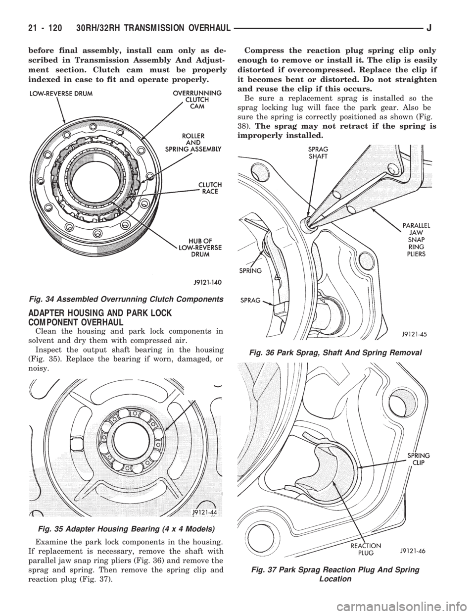
before final assembly, install cam only as de-
scribed in Transmission Assembly And Adjust-
ment section. Clutch cam must be properly
indexed in case to fit and operate properly.
ADAPTER HOUSING AND PARK LOCK
COMPONENT OVERHAUL
Clean the housing and park lock components in
solvent and dry them with compressed air.
Inspect the output shaft bearing in the housing
(Fig. 35). Replace the bearing if worn, damaged, or
noisy.
Examine the park lock components in the housing.
If replacement is necessary, remove the shaft with
parallel jaw snap ring pliers (Fig. 36) and remove the
sprag and spring. Then remove the spring clip and
reaction plug (Fig. 37).Compress the reaction plug spring clip only
enough to remove or install it. The clip is easily
distorted if overcompressed. Replace the clip if
it becomes bent or distorted. Do not straighten
and reuse the clip if this occurs.
Be sure a replacement sprag is installed so the
sprag locking lug will face the park gear. Also be
sure the spring is correctly positioned as shown (Fig.
38).The sprag may not retract if the spring is
improperly installed.
Fig. 34 Assembled Overrunning Clutch Components
Fig. 35 Adapter Housing Bearing (4 x 4 Models)
Fig. 36 Park Sprag, Shaft And Spring Removal
Fig. 37 Park Sprag Reaction Plug And Spring
Location
21 - 120 30RH/32RH TRANSMISSION OVERHAULJ
Page 1235 of 1784
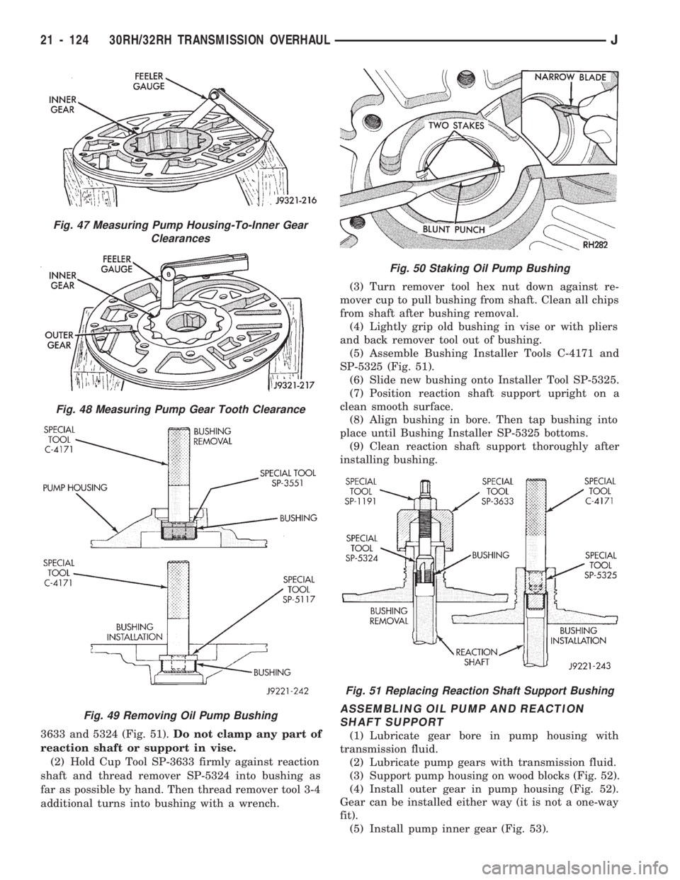
3633 and 5324 (Fig. 51).Do not clamp any part of
reaction shaft or support in vise.
(2) Hold Cup Tool SP-3633 firmly against reaction
shaft and thread remover SP-5324 into bushing as
far as possible by hand. Then thread remover tool 3-4
additional turns into bushing with a wrench.(3) Turn remover tool hex nut down against re-
mover cup to pull bushing from shaft. Clean all chips
from shaft after bushing removal.
(4) Lightly grip old bushing in vise or with pliers
and back remover tool out of bushing.
(5) Assemble Bushing Installer Tools C-4171 and
SP-5325 (Fig. 51).
(6) Slide new bushing onto Installer Tool SP-5325.
(7) Position reaction shaft support upright on a
clean smooth surface.
(8) Align bushing in bore. Then tap bushing into
place until Bushing Installer SP-5325 bottoms.
(9) Clean reaction shaft support thoroughly after
installing bushing.
ASSEMBLING OIL PUMP AND REACTION
SHAFT SUPPORT
(1) Lubricate gear bore in pump housing with
transmission fluid.
(2) Lubricate pump gears with transmission fluid.
(3) Support pump housing on wood blocks (Fig. 52).
(4) Install outer gear in pump housing (Fig. 52).
Gear can be installed either way (it is not a one-way
fit).
(5) Install pump inner gear (Fig. 53).
Fig. 47 Measuring Pump Housing-To-Inner Gear
Clearances
Fig. 48 Measuring Pump Gear Tooth Clearance
Fig. 49 Removing Oil Pump Bushing
Fig. 50 Staking Oil Pump Bushing
Fig. 51 Replacing Reaction Shaft Support Bushing
21 - 124 30RH/32RH TRANSMISSION OVERHAULJ
Page 1237 of 1784
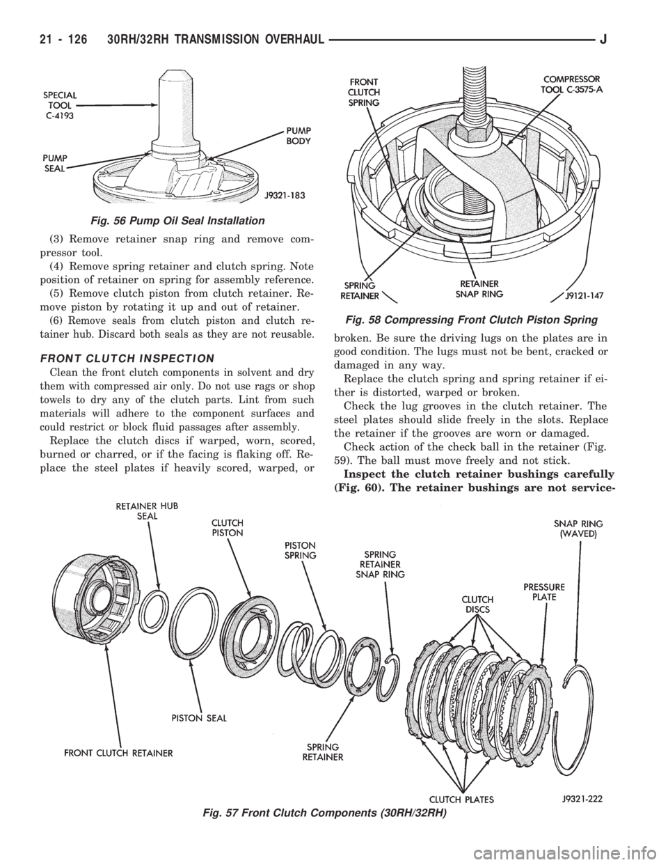
(3) Remove retainer snap ring and remove com-
pressor tool.
(4) Remove spring retainer and clutch spring. Note
position of retainer on spring for assembly reference.
(5) Remove clutch piston from clutch retainer. Re-
move piston by rotating it up and out of retainer.
(6) Remove seals from clutch piston and clutch re-
tainer hub. Discard both seals as they are not reusable.
FRONT CLUTCH INSPECTION
Clean the front clutch components in solvent and dry
them with compressed air only. Do not use rags or shop
towels to dry any of the clutch parts. Lint from such
materials will adhere to the component surfaces and
could restrict or block fluid passages after assembly.
Replace the clutch discs if warped, worn, scored,
burned or charred, or if the facing is flaking off. Re-
place the steel plates if heavily scored, warped, orbroken. Be sure the driving lugs on the plates are in
good condition. The lugs must not be bent, cracked or
damaged in any way.
Replace the clutch spring and spring retainer if ei-
ther is distorted, warped or broken.
Check the lug grooves in the clutch retainer. The
steel plates should slide freely in the slots. Replace
the retainer if the grooves are worn or damaged.
Check action of the check ball in the retainer (Fig.
59). The ball must move freely and not stick.
Inspect the clutch retainer bushings carefully
(Fig. 60). The retainer bushings are not service-
Fig. 56 Pump Oil Seal Installation
Fig. 57 Front Clutch Components (30RH/32RH)
Fig. 58 Compressing Front Clutch Piston Spring
21 - 126 30RH/32RH TRANSMISSION OVERHAULJ
Page 1239 of 1784
REAR CLUTCH OVERHAUL
REAR CLUTCH DISASSEMBLY
(1) Remove fiber thrust washer from forward side
of clutch retainer.
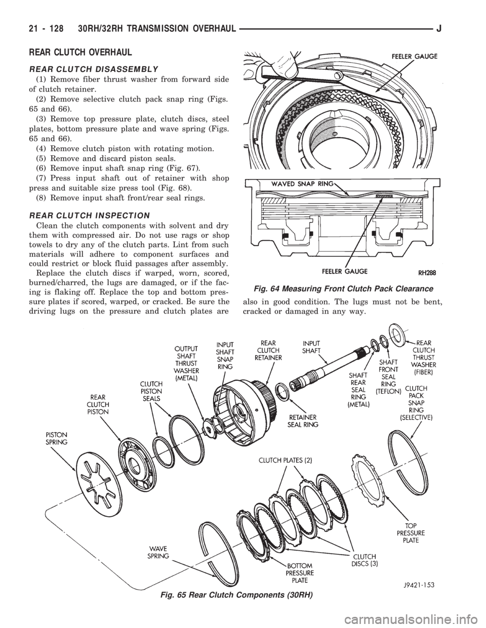
(2) Remove selective clutch pack snap ring (Figs.
65 and 66).
(3) Remove top pressure plate, clutch discs, steel
plates, bottom pressure plate and wave spring (Figs.
65 and 66).
(4) Remove clutch piston with rotating motion.
(5) Remove and discard piston seals.
(6) Remove input shaft snap ring (Fig. 67).
(7) Press input shaft out of retainer with shop
press and suitable size press tool (Fig. 68).
(8) Remove input shaft front/rear seal rings.
REAR CLUTCH INSPECTION
Clean the clutch components with solvent and dry
them with compressed air. Do not use rags or shop
towels to dry any of the clutch parts. Lint from such
materials will adhere to component surfaces and
could restrict or block fluid passages after assembly.
Replace the clutch discs if warped, worn, scored,
burned/charred, the lugs are damaged, or if the fac-
ing is flaking off. Replace the top and bottom pres-
sure plates if scored, warped, or cracked. Be sure the
driving lugs on the pressure and clutch plates arealso in good condition. The lugs must not be bent,
cracked or damaged in any way.
Fig. 64 Measuring Front Clutch Pack Clearance
Fig. 65 Rear Clutch Components (30RH)
21 - 128 30RH/32RH TRANSMISSION OVERHAULJ
Page 1241 of 1784
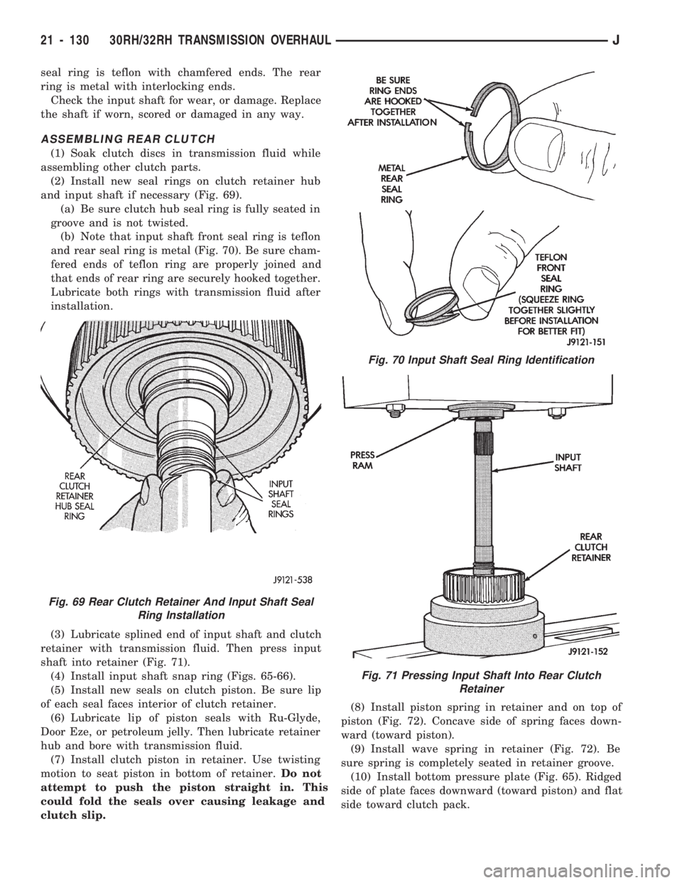
seal ring is teflon with chamfered ends. The rear
ring is metal with interlocking ends.
Check the input shaft for wear, or damage. Replace
the shaft if worn, scored or damaged in any way.
ASSEMBLING REAR CLUTCH
(1) Soak clutch discs in transmission fluid while
assembling other clutch parts.
(2) Install new seal rings on clutch retainer hub
and input shaft if necessary (Fig. 69).
(a) Be sure clutch hub seal ring is fully seated in
groove and is not twisted.
(b) Note that input shaft front seal ring is teflon
and rear seal ring is metal (Fig. 70). Be sure cham-
fered ends of teflon ring are properly joined and
that ends of rear ring are securely hooked together.
Lubricate both rings with transmission fluid after
installation.
(3) Lubricate splined end of input shaft and clutch
retainer with transmission fluid. Then press input
shaft into retainer (Fig. 71).
(4) Install input shaft snap ring (Figs. 65-66).
(5) Install new seals on clutch piston. Be sure lip
of each seal faces interior of clutch retainer.
(6) Lubricate lip of piston seals with Ru-Glyde,
Door Eze, or petroleum jelly. Then lubricate retainer
hub and bore with transmission fluid.
(7) Install clutch piston in retainer. Use twisting
motion to seat piston in bottom of retainer.Do not
attempt to push the piston straight in. This
could fold the seals over causing leakage and
clutch slip.(8) Install piston spring in retainer and on top of
piston (Fig. 72). Concave side of spring faces down-
ward (toward piston).
(9) Install wave spring in retainer (Fig. 72). Be
sure spring is completely seated in retainer groove.
(10) Install bottom pressure plate (Fig. 65). Ridged
side of plate faces downward (toward piston) and flat
side toward clutch pack.
Fig. 69 Rear Clutch Retainer And Input Shaft Seal
Ring Installation
Fig. 70 Input Shaft Seal Ring Identification
Fig. 71 Pressing Input Shaft Into Rear Clutch
Retainer
21 - 130 30RH/32RH TRANSMISSION OVERHAULJ
Page 1244 of 1784
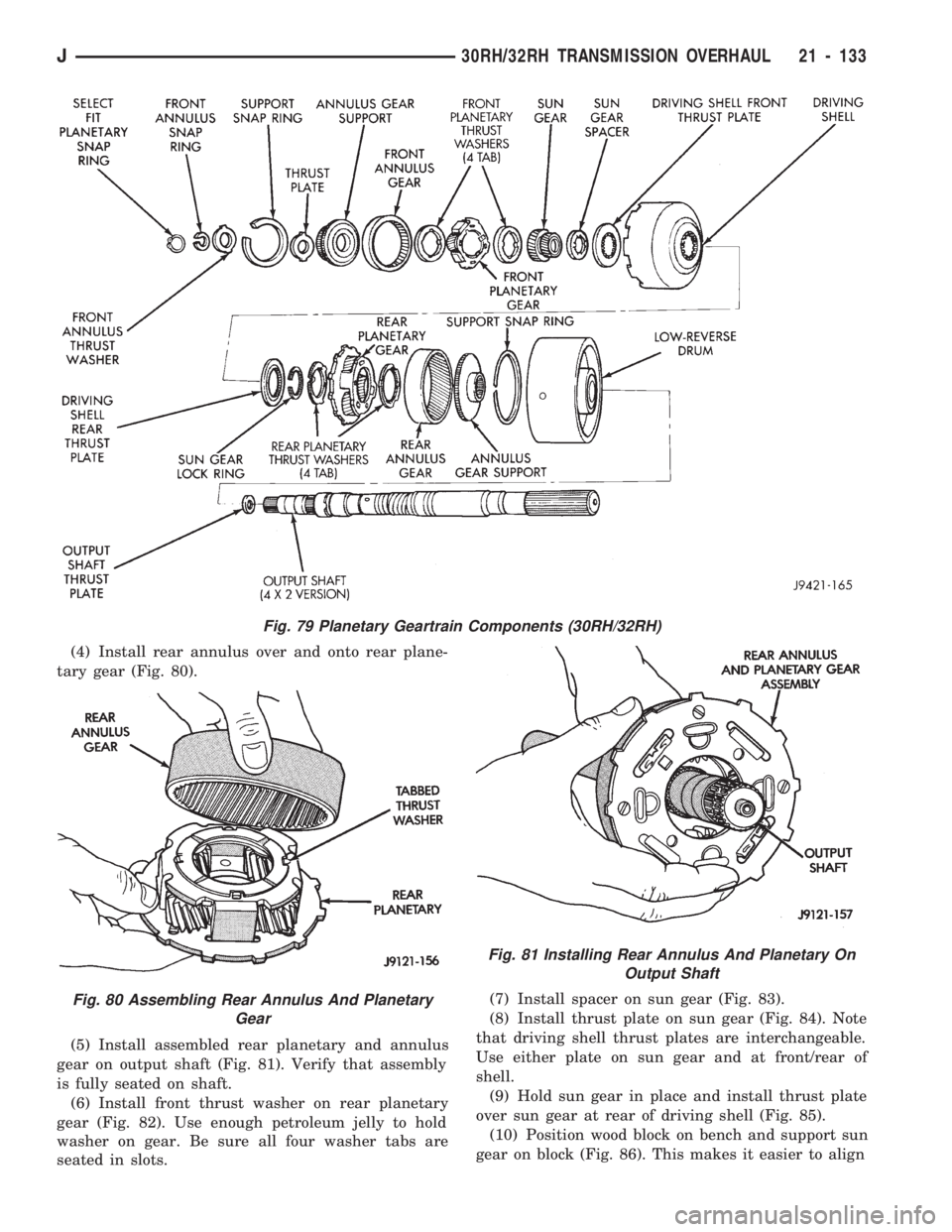
(4) Install rear annulus over and onto rear plane-
tary gear (Fig. 80).
(5) Install assembled rear planetary and annulus
gear on output shaft (Fig. 81). Verify that assembly
is fully seated on shaft.
(6) Install front thrust washer on rear planetary
gear (Fig. 82). Use enough petroleum jelly to hold
washer on gear. Be sure all four washer tabs are
seated in slots.(7) Install spacer on sun gear (Fig. 83).
(8) Install thrust plate on sun gear (Fig. 84). Note
that driving shell thrust plates are interchangeable.
Use either plate on sun gear and at front/rear of
shell.
(9) Hold sun gear in place and install thrust plate
over sun gear at rear of driving shell (Fig. 85).
(10) Position wood block on bench and support sun
gear on block (Fig. 86). This makes it easier to align
Fig. 79 Planetary Geartrain Components (30RH/32RH)
Fig. 80 Assembling Rear Annulus And Planetary
Gear
Fig. 81 Installing Rear Annulus And Planetary On
Output Shaft
J30RH/32RH TRANSMISSION OVERHAUL 21 - 133
Page 1245 of 1784
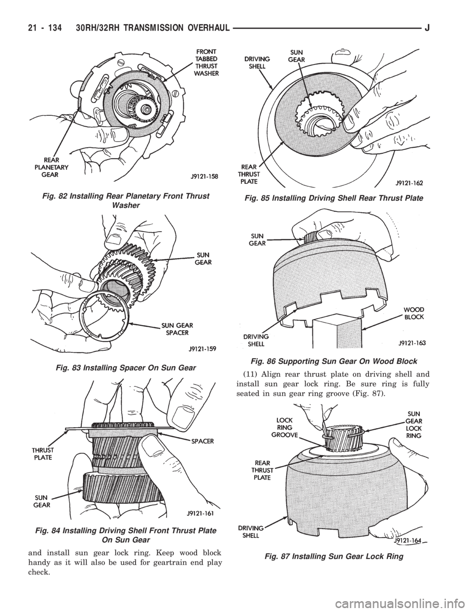
and install sun gear lock ring. Keep wood block
handy as it will also be used for geartrain end play
check.(11) Align rear thrust plate on driving shell and
install sun gear lock ring. Be sure ring is fully
seated in sun gear ring groove (Fig. 87).
Fig. 82 Installing Rear Planetary Front Thrust
Washer
Fig. 83 Installing Spacer On Sun Gear
Fig. 84 Installing Driving Shell Front Thrust Plate
On Sun Gear
Fig. 85 Installing Driving Shell Rear Thrust Plate
Fig. 86 Supporting Sun Gear On Wood Block
Fig. 87 Installing Sun Gear Lock Ring
21 - 134 30RH/32RH TRANSMISSION OVERHAULJ
Page 1247 of 1784
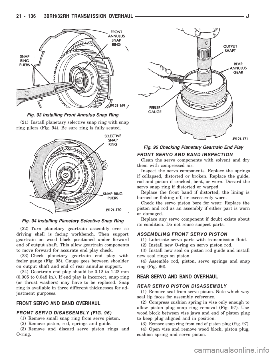
(21) Install planetary selective snap ring with snap
ring pliers (Fig. 94). Be sure ring is fully seated.
(22) Turn planetary geartrain assembly over so
driving shell is facing workbench. Then support
geartrain on wood block positioned under forward
end of output shaft. This allow geartrain components
to move forward for accurate end play check.
(23) Check planetary geartrain end play with
feeler gauge (Fig. 95). Gauge goes between shoulder
on output shaft and end of rear annulus support.
(24) Geartrain end play should be 0.12 to 1.22 mm
(0.005 to 0.048 in.). If end play is incorrect, snap ring
(or thrust washers) may have to be replaced. Snap
ring is available in three different thicknesses for ad-
justment purposes.
FRONT SERVO AND BAND OVERHAUL
FRONT SERVO DISASSEMBLY (FIG. 96)
(1) Remove small snap ring from servo piston.
(2) Remove piston, rod, springs and guide.
(3) Remove and discard servo piston rings and
O-ring.
FRONT SERVO AND BAND INSPECTION
Clean the servo components with solvent and dry
them with compressed air.
Inspect the servo components. Replace the springs
if collapsed, distorted or broken. Replace the guide,
rod and piston if cracked, bent, or worn. Discard the
servo snap ring if distorted or warped.
Replace the front band if distorted, the lining is
burned or flaking off, or excessively worn.
Check the servo piston bore for wear. Replace the
piston and rod as an assembly if either part is worn
or damaged.
Replace any servo component if doubt exists about
its condition. Do not reuse suspect parts.
ASSEMBLING FRONT SERVO PISTON
(1) Lubricate servo parts with transmission fluid.
(2) Install new O-ring on servo piston rod.
(3) Install new seal on piston rod guide and install
new seal rings on piston.
(4) Assemble rod, piston, servo springs and snap
ring (Fig. 96).
REAR SERVO AND BAND OVERHAUL
REAR SERVO PISTON DISASSEMBLY
(1) Remove seal from servo piston. Note which way
seal lip faces for assembly reference.
(2) Compress cushion spring in vise only enough to
allow piston plug snap ring removal (Fig. 97). Use
wood block between vise jaws and end of piston plug
to keep plug aligned and in position.
(3)
Remove snap ring from end of piston plug (Fig. 97).
(4) Open vise and remove wood block, piston plug,
cushion spring and servo piston.
Fig. 93 Installing Front Annulus Snap Ring
Fig. 94 Installing Planetary Selective Snap Ring
Fig. 95 Checking Planetary Geartrain End Play
21 - 136 30RH/32RH TRANSMISSION OVERHAULJ