1994 JEEP CHEROKEE lock
[x] Cancel search: lockPage 1216 of 1784
(10) Install speedometer adapter clamp and retain-
ing screw. Tighten clamp screw to 10-12 Nzm (90-110
in. lbs.) torque.
(11) Connect wires to vehicle speed sensor.
(12) Lower vehicle and top off transmission fluid
level if necessary.
SPEEDOMETER COMPONENT REMOVAL
(TWO-PIECE SENSOR)
(1) Raise vehicle.
(2) Disconnect speed sensor wires.
(3) Remove bolt attaching vehicle speed sensor to
sensor adapter. Then slide sensor out of adapter.
(4) Inspect speed sensor mounting area in sensor
adapter. If transmission fluid is found in this area,
oil seal in metal speedometer adapter is leaking and
will have to be replaced.
(5) Remove speedometer adapter clamp bolt and
remove clamp (Fig. 18).
(6) Remove speedometer adapter, sensor adapter
and speedometer pinion as assembly.
SPEEDOMETER COMPONENT INSTALLATION
AND INDEXING (TWO-PIECE SENSOR)
(1) Replace speedometer O-ring if cut, torn, or worn.
(2) If oil seal in metal speedometer adapter needs
replacement, remove old seal with pointed tool. Then
install new seal with Special Tool C-4004. Push seal
into place with tool until tool bottoms (Fig. 19).
(3) Clean speedometer adapter mounting surface of
transmission, or transfer case thoroughly.
(4) Lubricate adapter seals with transmission fluid.
(5) Count number of teeth on speedometer pinion.
Do this before installing pinion and adapter.
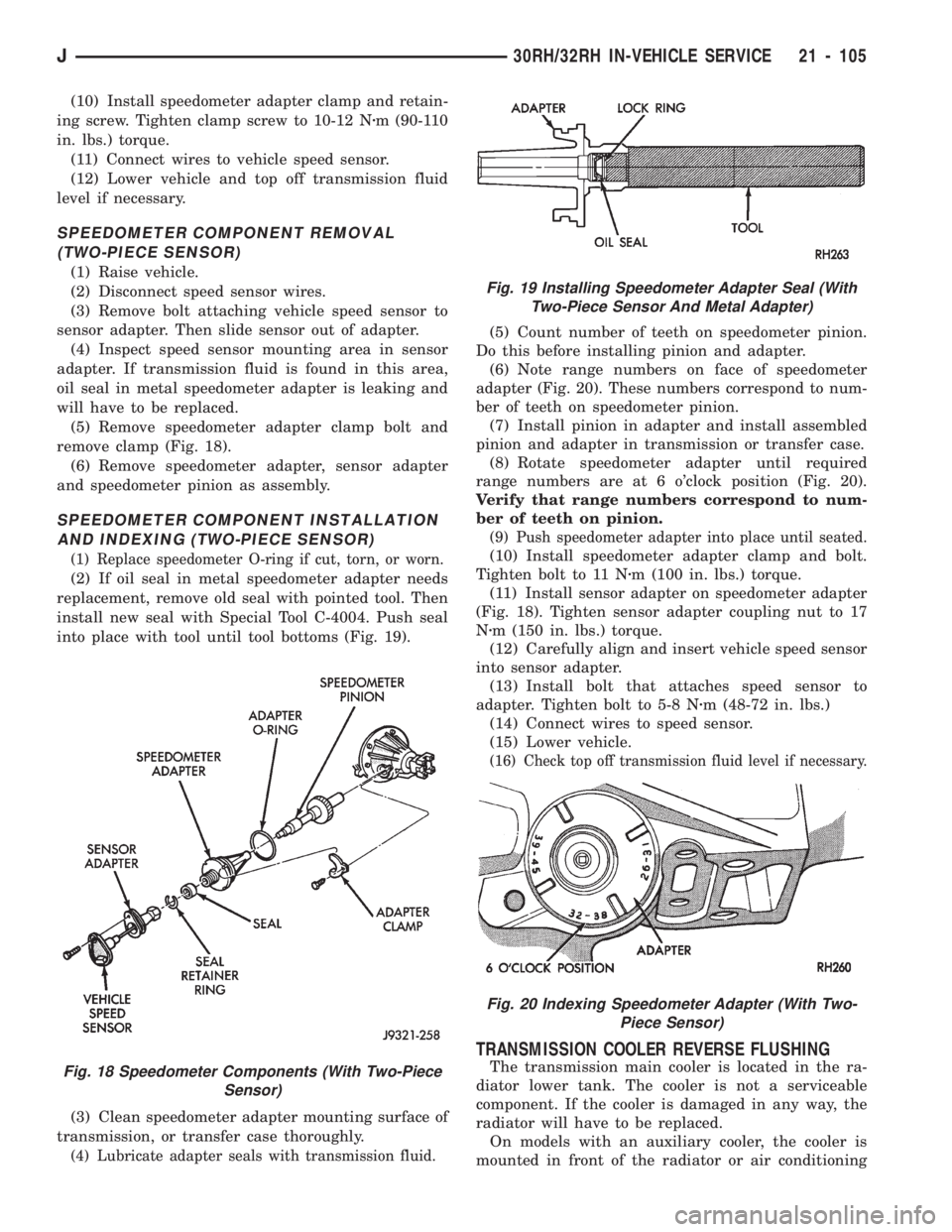
(6) Note range numbers on face of speedometer
adapter (Fig. 20). These numbers correspond to num-
ber of teeth on speedometer pinion.
(7) Install pinion in adapter and install assembled
pinion and adapter in transmission or transfer case.
(8) Rotate speedometer adapter until required
range numbers are at 6 o'clock position (Fig. 20).
Verify that range numbers correspond to num-
ber of teeth on pinion.
(9) Push speedometer adapter into place until seated.
(10) Install speedometer adapter clamp and bolt.
Tighten bolt to 11 Nzm (100 in. lbs.) torque.
(11) Install sensor adapter on speedometer adapter
(Fig. 18). Tighten sensor adapter coupling nut to 17
Nzm (150 in. lbs.) torque.
(12) Carefully align and insert vehicle speed sensor
into sensor adapter.
(13) Install bolt that attaches speed sensor to
adapter. Tighten bolt to 5-8 Nzm (48-72 in. lbs.)
(14) Connect wires to speed sensor.
(15) Lower vehicle.
(16) Check top off transmission fluid level if necessary.
TRANSMISSION COOLER REVERSE FLUSHING
The transmission main cooler is located in the ra-
diator lower tank. The cooler is not a serviceable
component. If the cooler is damaged in any way, the
radiator will have to be replaced.
On models with an auxiliary cooler, the cooler is
mounted in front of the radiator or air conditioningFig. 18 Speedometer Components (With Two-Piece
Sensor)
Fig. 19 Installing Speedometer Adapter Seal (With
Two-Piece Sensor And Metal Adapter)
Fig. 20 Indexing Speedometer Adapter (With Two-
Piece Sensor)
J30RH/32RH IN-VEHICLE SERVICE 21 - 105
Page 1218 of 1784
Fitting And Cooler Line Service
The cooler lines and quick disconnect fittings are
NOT serviceable. Damaged fittings or cooler lines
are to be replaced as assemblies.
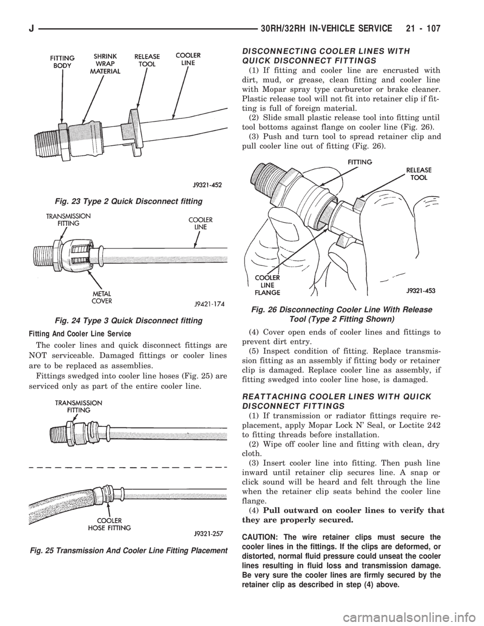
Fittings swedged into cooler line hoses (Fig. 25) are
serviced only as part of the entire cooler line.
DISCONNECTING COOLER LINES WITH
QUICK DISCONNECT FITTINGS
(1) If fitting and cooler line are encrusted with
dirt, mud, or grease, clean fitting and cooler line
with Mopar spray type carburetor or brake cleaner.
Plastic release tool will not fit into retainer clip if fit-
ting is full of foreign material.
(2) Slide small plastic release tool into fitting until
tool bottoms against flange on cooler line (Fig. 26).
(3) Push and turn tool to spread retainer clip and
pull cooler line out of fitting (Fig. 26).
(4) Cover open ends of cooler lines and fittings to
prevent dirt entry.
(5) Inspect condition of fitting. Replace transmis-
sion fitting as an assembly if fitting body or retainer
clip is damaged. Replace cooler line as assembly, if
fitting swedged into cooler line hose, is damaged.
REATTACHING COOLER LINES WITH QUICK
DISCONNECT FITTINGS
(1) If transmission or radiator fittings require re-
placement, apply Mopar Lock N' Seal, or Loctite 242
to fitting threads before installation.
(2) Wipe off cooler line and fitting with clean, dry
cloth.
(3) Insert cooler line into fitting. Then push line
inward until retainer clip secures line. A snap or
click sound will be heard and felt through the line
when the retainer clip seats behind the cooler line
flange.
(4)Pull outward on cooler lines to verify that
they are properly secured.
CAUTION: The wire retainer clips must secure the
cooler lines in the fittings. If the clips are deformed, or
distorted, normal fluid pressure could unseat the cooler
lines resulting in fluid loss and transmission damage.
Be very sure the cooler lines are firmly secured by the
retainer clip as described in step (4) above.
Fig. 23 Type 2 Quick Disconnect fitting
Fig. 24 Type 3 Quick Disconnect fitting
Fig. 25 Transmission And Cooler Line Fitting Placement
Fig. 26 Disconnecting Cooler Line With Release
Tool (Type 2 Fitting Shown)
J30RH/32RH IN-VEHICLE SERVICE 21 - 107
Page 1219 of 1784
30RH/32RH TRANSMISSION REMOVAL AND INSTALLATION
INDEX
page page
ConverterÐPump SealÐDrive Plate Service . . . 109
Transmission and Converter Installation....... 109Transmission and Converter Removal........ 108
TRANSMISSION AND CONVERTER REMOVAL
(1) Remove fan shroud attaching bolts.
(2) Disconnect transmission fill tube at upper
bracket.
(3) Raise vehicle.
(4) Remove inspection cover from converter hous-
ing and remove skid plate for access, if necessary.
(5) Remove transmission fill tube and fill tube
O-ring.
(6) Remove starter motor.
(7) Mark propeller shafts and axle yokes for align-
ment reference.
(8) Disconnect propeller shafts at yokes. Secure
shafts to frame rails with wire.
(9) Disconnect exhaust pipes at exhaust manifolds,
if necessary.
(10) Drain transfer case lubricant.
(11) Disconnect vehicle speed sensor wires.
(12) Disconnect transfer case shift linkage.
(13) Disconnect gearshift linkage and throttle ca-
ble at transmission levers.
(14) Disconnect park/neutral position switch wires.
(15) Disconnect and remove crankshaft position
sensor. Retain sensor bolt for reinstallation.
CAUTION: The crankshaft position sensor can be
damaged during transmission removal (or installa-
tion) if the sensor is still bolted to the engine block.
To avoid damage, remove the sensor before remov-
ing the transmission.
(16) Remove converter housing access cover and
mark drive plate and converter for alignment refer-
ence.
(17) Remove bolts attaching converter to drive
plate.
(18) Support engine with support stand.
(19) Support transmission-transfer case assembly
with transmission jack. Secure transmission to jack
with safety chain.
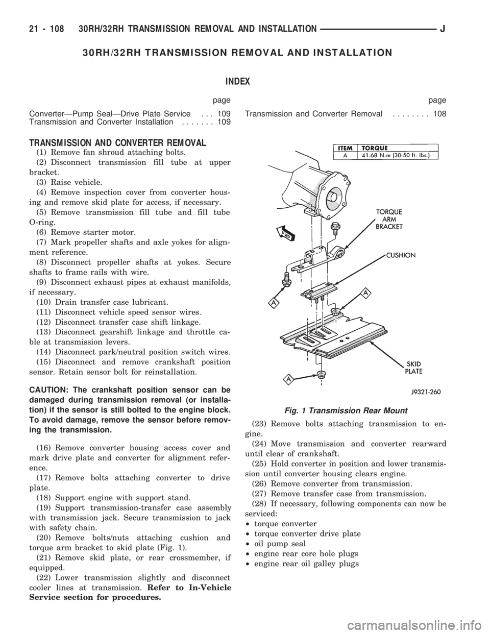
(20) Remove bolts/nuts attaching cushion and
torque arm bracket to skid plate (Fig. 1).
(21) Remove skid plate, or rear crossmember, if
equipped.
(22) Lower transmission slightly and disconnect
cooler lines at transmission.Refer to In-Vehicle
Service section for procedures.(23) Remove bolts attaching transmission to en-
gine.
(24) Move transmission and converter rearward
until clear of crankshaft.
(25) Hold converter in position and lower transmis-
sion until converter housing clears engine.
(26) Remove converter from transmission.
(27) Remove transfer case from transmission.
(28) If necessary, following components can now be
serviced:
²torque converter
²torque converter drive plate
²oil pump seal
²engine rear core hole plugs
²engine rear oil galley plugs
Fig. 1 Transmission Rear Mount
21 - 108 30RH/32RH TRANSMISSION REMOVAL AND INSTALLATIONJ
Page 1221 of 1784
(1) Lubricate converter drive hub and pump seal
with Mopar ATF Plus, or Dexron II transmission
fluid. Then install converter. Turn converter back
and forth to align drive slots in converter hub with
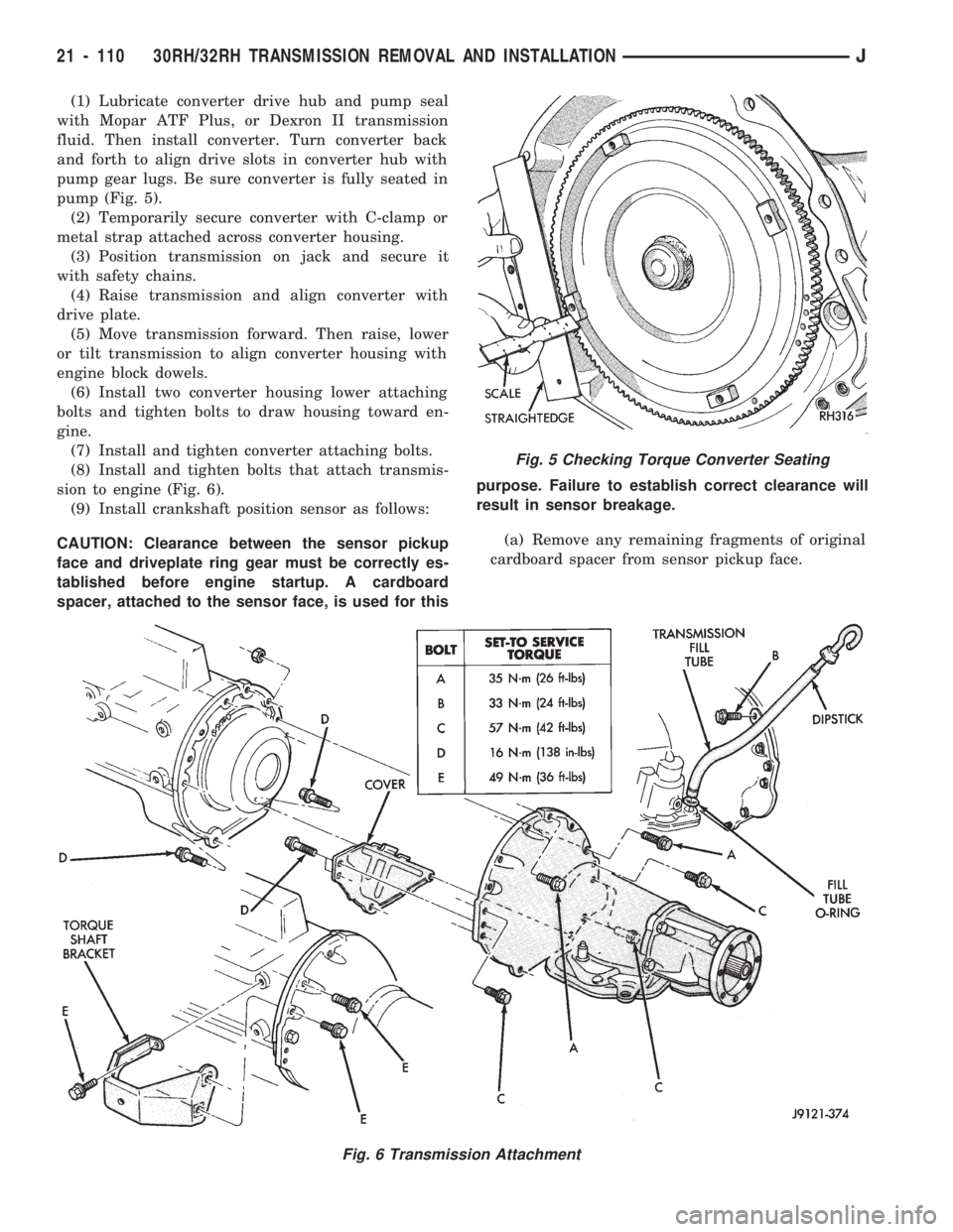
pump gear lugs. Be sure converter is fully seated in
pump (Fig. 5).
(2) Temporarily secure converter with C-clamp or
metal strap attached across converter housing.
(3) Position transmission on jack and secure it
with safety chains.
(4) Raise transmission and align converter with
drive plate.
(5) Move transmission forward. Then raise, lower
or tilt transmission to align converter housing with
engine block dowels.
(6) Install two converter housing lower attaching
bolts and tighten bolts to draw housing toward en-
gine.
(7) Install and tighten converter attaching bolts.
(8) Install and tighten bolts that attach transmis-
sion to engine (Fig. 6).
(9) Install crankshaft position sensor as follows:
CAUTION: Clearance between the sensor pickup
face and driveplate ring gear must be correctly es-
tablished before engine startup. A cardboard
spacer, attached to the sensor face, is used for thispurpose. Failure to establish correct clearance will
result in sensor breakage.
(a) Remove any remaining fragments of original
cardboard spacer from sensor pickup face.
Fig. 5 Checking Torque Converter Seating
Fig. 6 Transmission Attachment
21 - 110 30RH/32RH TRANSMISSION REMOVAL AND INSTALLATIONJ
Page 1223 of 1784
30RH/32RH TRANSMISSION OVERHAUL
INDEX
page page
Adapter Housing and Park Lock Component
Overhaul............................ 120
Front Clutch Overhaul.................... 125
Front Servo and Band Overhaul............ 136
Governor and Park Gear Overhaul.......... 121
Oil Pump Overhaul...................... 122
Overhaul Service Information............... 118
Overrunning ClutchÐLow-Reverse DrumÐRear
Support Overhaul...................... 118
Planetary Gear Train Overhaul............. 131Rear Clutch Overhaul.................... 128
Rear Servo and Band Overhaul............. 136
Transmission Assembly and Adjustment
Procedures........................... 146
Transmission Assembly Tips............... 146
Transmission Case Cleaning and Inspection . . . 118
Transmission Disassembly................. 112
Valve Body Assembly and Adjustment........ 144
Valve Body Disassembly and Inspection...... 138
TRANSMISSION DISASSEMBLY
(1) Clean transmission exterior with steam gun or
with solvent. Wear eye protection during cleaning
process.
(2) Remove throttle and shift levers from valve
body manual shaft and throttle lever shaft.
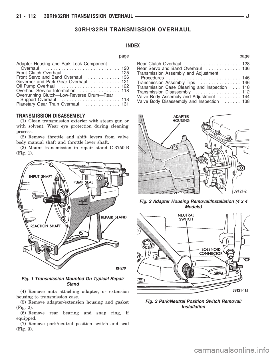
(3) Mount transmission in repair stand C-3750-B
(Fig. 1).
(4) Remove nuts attaching adapter, or extension
housing to transmission case.
(5) Remove adapter/extension housing and gasket
(Fig. 2).
(6) Remove rear bearing and snap ring, if
equipped.
(7) Remove park/neutral position switch and seal
(Fig. 3).
Fig. 1 Transmission Mounted On Typical Repair
Stand
Fig. 2 Adapter Housing Removal/Installation (4 x 4
Models)
Fig. 3 Park/Neutral Position Switch Removal/
Installation
21 - 112 30RH/32RH TRANSMISSION OVERHAULJ
Page 1224 of 1784
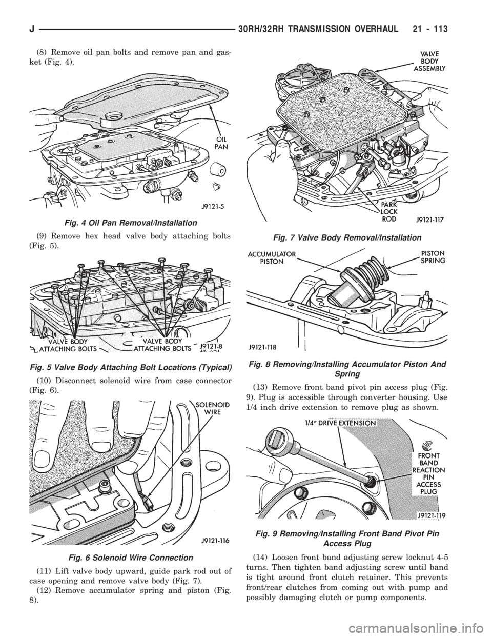
(8) Remove oil pan bolts and remove pan and gas-
ket (Fig. 4).
(9) Remove hex head valve body attaching bolts
(Fig. 5).
(10) Disconnect solenoid wire from case connector
(Fig. 6).
(11) Lift valve body upward, guide park rod out of
case opening and remove valve body (Fig. 7).
(12) Remove accumulator spring and piston (Fig.
8).(13) Remove front band pivot pin access plug (Fig.
9). Plug is accessible through converter housing. Use
1/4 inch drive extension to remove plug as shown.
(14) Loosen front band adjusting screw locknut 4-5
turns. Then tighten band adjusting screw until band
is tight around front clutch retainer. This prevents
front/rear clutches from coming out with pump and
possibly damaging clutch or pump components.
Fig. 4 Oil Pan Removal/Installation
Fig. 5 Valve Body Attaching Bolt Locations (Typical)
Fig. 6 Solenoid Wire Connection
Fig. 7 Valve Body Removal/Installation
Fig. 8 Removing/Installing Accumulator Piston And
Spring
Fig. 9 Removing/Installing Front Band Pivot Pin
Access Plug
J30RH/32RH TRANSMISSION OVERHAUL 21 - 113
Page 1229 of 1784
OVERHAUL SERVICE INFORMATION
Inspect the transmission bushings during overhaul.
Bushing condition is important as severely worn, or
scored bushings contribute to low pressures, clutch
slip and accelerated wear of other components.How-
ever, do not replace bushings as a matter of
course. Replace bushings only when they are
actually worn, or scored.
Use recommended tools to replace bushings. The
tools are sized and designed to remove, install and
seat bushings correctly. The bushing replacement
tools are included in Bushing Tool Set C-3887-B. The
tool set is manufactured by Miller Tool Co. and is
available through the dealer tool program.
Pre-sized service bushings are available for replace-
ment purposes. Only the sun gear bushings are not
serviced. Low cost of the sun gear assembly makes it
easier to simply replace the gear and bushings as an
assembly.
Heli-Coil inserts are recommended for repairing
damaged, stripped or worn threads in aluminum
parts. These inserts are available from most automo-
tive jobbers. Stainless steel inserts are preferred.
The use of crocus cloth is permissible where neces-
sary. When used on valves, use care to avoid round-
ing off sharp edges. Sharp edges are vital as they
prevent foreign matter from getting between the
valve and valve bore.
Do not reuse oil seals, gaskets, seal rings, or O-
rings during overhaul. Replace these parts as a mat-
ter of course. Also do not reuse snap rings or E-clips
that are bent or distorted. Replace these parts as
well.
Lubricate transmission parts with Mopar ATF
Plus, Type 7176 transmission fluid during overhaul
and assembly.Use petroleum jelly to hold parts like thrust wash-
ers in place during assembly. Use Ru-Glyde, Door
Eze, or similar products to lubricate piston seals and
O-rings to ease installation. Petroleum jelly can also
be used to prelubricate parts during reassembly if de-
sired.
TRANSMISSION CASE CLEANING AND
INSPECTION
Clean the case in a solvent tank. Flush the case
bores and fluid passages thoroughly with solvent.
Dry the case and all fluid passages with compressed
air. Be sure all solvent is removed from the case and
that all fluid passages are clear.
Do not use shop towels or rags to dry the case
(or any other transmission component) unless
they are made from lint-free materials. Lint will
readily adhere to case surfaces and transmission
components and will circulate throughout the
transmission after assembly. A sufficient quan-
tity of lint can block fluid passages and interfere
with valve body operation.
Inspect the case for cracks, porous spots, worn
bores, or damaged threads. Damaged threads can be
repaired with Helicoil thread inserts. However, the
case will have to be replaced if it exhibits any type of
damage or wear.
Lubricate the front band adjusting screw threads
with petroleum jelly and thread the screw part-way
into the case. Be sure the screw turns freely.
Remount the case in a repair stand after cleaning
and inspection.
OVERRUNNING CLUTCHÐLOW-REVERSE
DRUMÐREAR SUPPORT OVERHAUL
DISASSEMBLING OVERRUNNING CLUTCH/
LOW-REVERSE DRUM
If the clutch assembly came out with the low-re-
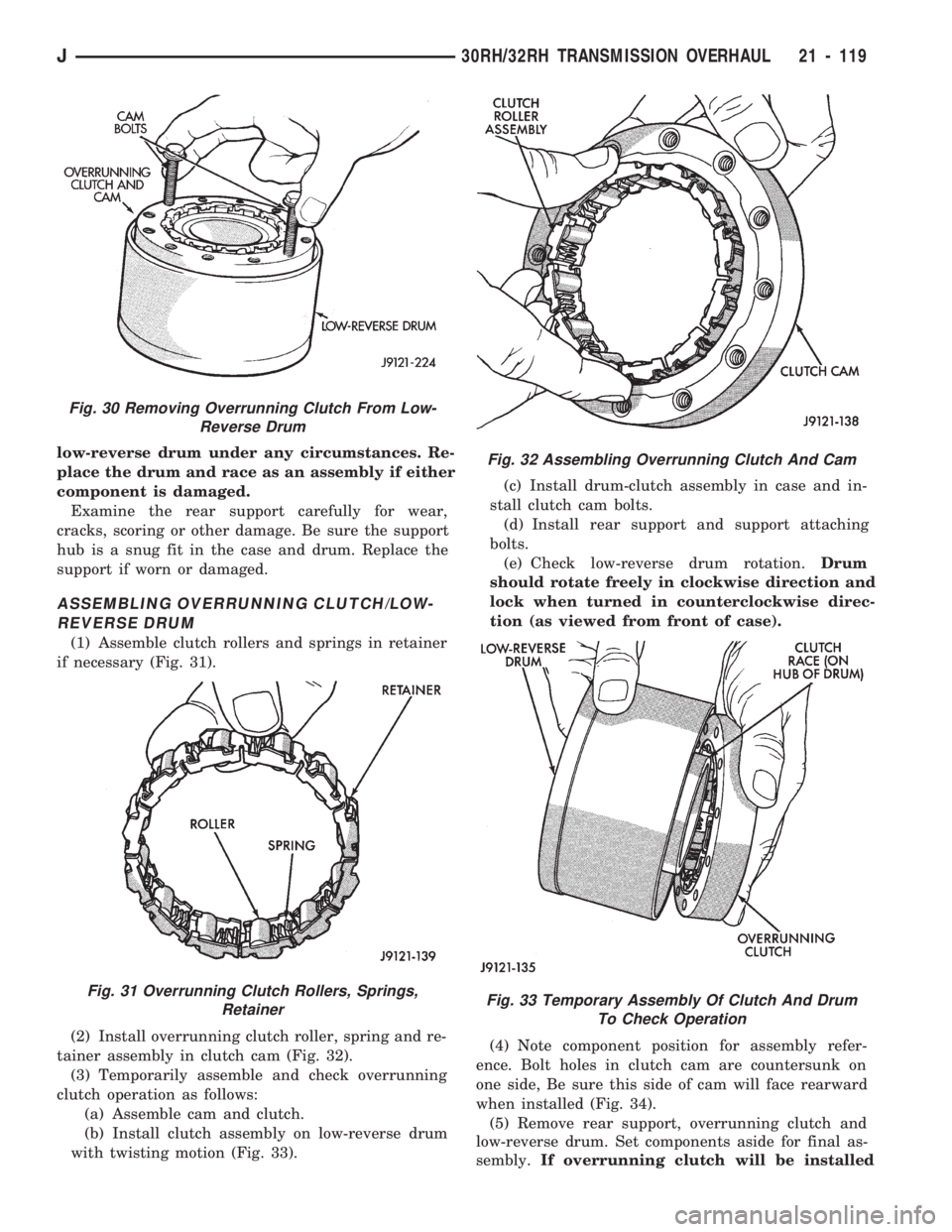
verse drum, thread two clutch cam bolts into the
cam. Then lift the cam out of the drum with the bolts
(Fig. 30). Rotate the cam back and forth to ease re-
moval if necessary. Remove the clutch roller and
spring assembly from the race afterward.
CLEANING AND INSPECTION
Clean the overrunning clutch assembly, clutch
cam, low-reverse drum and rear support in solvent.
Dry them with compressed air after cleaning.
Inspect condition of each clutch part after cleaning.
Replace the overrunning clutch roller and spring as-
sembly if any rollers or springs are worn or dam-
aged, or if the roller cage is distorted, or damaged.
Replace the cam if worn, cracked or damaged.
Replace the low-reverse drum if the clutch race,
roller surface or inside diameter is scored, worn or
damaged.Do not remove the clutch race from the
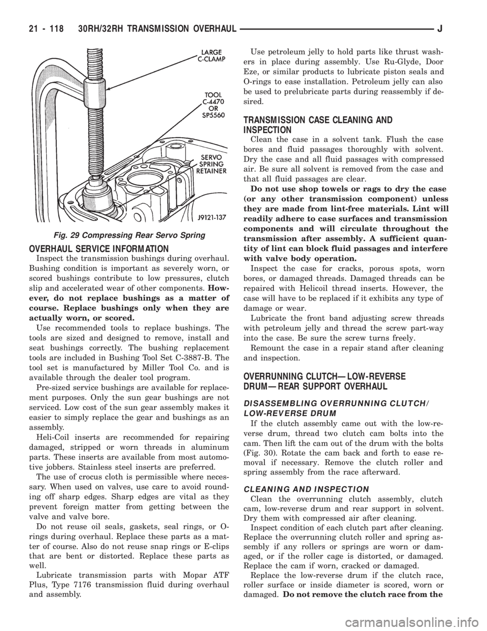
Fig. 29 Compressing Rear Servo Spring
21 - 118 30RH/32RH TRANSMISSION OVERHAULJ
Page 1230 of 1784
low-reverse drum under any circumstances. Re-
place the drum and race as an assembly if either
component is damaged.
Examine the rear support carefully for wear,
cracks, scoring or other damage. Be sure the support
hub is a snug fit in the case and drum. Replace the
support if worn or damaged.
ASSEMBLING OVERRUNNING CLUTCH/LOW-
REVERSE DRUM
(1) Assemble clutch rollers and springs in retainer
if necessary (Fig. 31).
(2) Install overrunning clutch roller, spring and re-
tainer assembly in clutch cam (Fig. 32).
(3) Temporarily assemble and check overrunning
clutch operation as follows:
(a) Assemble cam and clutch.
(b) Install clutch assembly on low-reverse drum
with twisting motion (Fig. 33).(c) Install drum-clutch assembly in case and in-
stall clutch cam bolts.
(d) Install rear support and support attaching
bolts.
(e) Check low-reverse drum rotation.Drum
should rotate freely in clockwise direction and
lock when turned in counterclockwise direc-
tion (as viewed from front of case).
(4) Note component position for assembly refer-
ence. Bolt holes in clutch cam are countersunk on
one side, Be sure this side of cam will face rearward
when installed (Fig. 34).
(5) Remove rear support, overrunning clutch and
low-reverse drum. Set components aside for final as-
sembly.If overrunning clutch will be installed
Fig. 30 Removing Overrunning Clutch From Low-
Reverse Drum
Fig. 31 Overrunning Clutch Rollers, Springs,
Retainer
Fig. 32 Assembling Overrunning Clutch And Cam
Fig. 33 Temporary Assembly Of Clutch And Drum
To Check Operation
J30RH/32RH TRANSMISSION OVERHAUL 21 - 119