Page 1312 of 1784
sion over and allow output shaft to support transmis-
sion weight. Place wood blocks under shaft to protect
splines (Fig. 35).
(45) Remove planetary snap ring and remove plan-
etary gear (Fig. 36).
(46) Remove sun gear, input drum and one-way
Fig. 33 Removing Front Planetary Ring Gear
Fig. 34 Removing Ring Gear Bearing And Rear Race
Fig. 35 Relieving Load On Planetary Snap Ring
Fig. 36 Removing Planetary Snap Ring And Gear
JAW-4 TRANSMISSION OVERHAUL 21 - 201
Page 1319 of 1784
(9) Remove old pump seal. Install new seal with
Seal Installer 7549 (Fig. 4).
(10) Lubricate and install gears in pump body.
(11) Assemble stator shaft and pump body. Tighten
shaft-to-body bolts to 10 Nzm (7 ft. lbs.) torque.
(12) Install new O-ring on pump body and new
seal rings on stator shaft.
(13) Install pump in torque converter and check
pump gear rotation. Gears must rotate smoothly
when turned clockwise and counterclockwise.
(14) Lubricate pump O-ring and seal rings with pe-
troleum jelly.
Fig. 5 Checking Pump Gear Rotation
Fig. 4 Installing Pump Seal
21 - 208 AW-4 TRANSMISSION OVERHAULJ
Page 1320 of 1784
OVERDRIVE PLANETARY GEAR AND CLUTCH
OVERHAUL
GEAR AND CLUTCH DISASSEMBLY
(1) Check operation of one-way clutch in clutch
drum. Hold drum and turn planetary shaft clockwise
and counterclockwise. Shaft should turn clockwise
freely but lock when turned counterclockwise. Re-
place one-way clutch if necessary.
(2) Remove overdrive clutch from planetary gear
(Fig. 3).
(3) Remove thrust bearing and race assembly from
clutch drum (Fig. 4).
Fig. 1 Overdrive Planetary Gear And Clutch Components
JAW-4 TRANSMISSION OVERHAUL 21 - 209
Page 1327 of 1784
mm (1.976 in.). Inside diameter is 28.9 mm (1.138 in.).
(16) Install clutch on planetary gear.
(17) Verify one-way clutch operation. Hold drum
and turn planetary shaft clockwise and counterclock-wise. Shaft should turn clockwise freely but lock
when turned counterclockwise.
OVERDRIVE SUPPORT OVERHAUL
SUPPORT DISASSEMBLY
(1) Check brake piston operation. Mount support
on clutch (Fig. 2).
(2) Apply compressed air through support feed hole
and observe brake piston movement (Fig. 2). Piston
Fig. 1 Overdrive Support Components
Fig. 26 Installing Retainer And Snap Ring
Fig. 27 Installing Clutch Drum Bearing And Race
Assembly
21 - 216 AW-4 TRANSMISSION OVERHAULJ
Page 1334 of 1784
FORWARD CLUTCH OVERHAUL
FORWARD CLUTCH DISASSEMBLY (FIG. 1)
(1) Check clutch piston stroke as outlined in fol-
lowing steps.
(2) Position overdrive support on wood blocks and
mount forward clutch drum on support (Fig. 2).
(3) Remove bearing and race from forward clutch
drum (Fig. 2).
(4) Mount dial indicator on clutch drum. Position
dial indicator plunger against clutch piston (Fig. 3).(5) Apply compressed air through right side feed
hole in support and note piston stroke length on dial
indicator.
(6) Stroke length should be 3.55 - 3.73 mm (0.1348
- 0.1469 in.).
(7) Replace clutch discs if stroke length is incor-
rect.
Fig. 1 Forward Clutch Components
JAW-4 TRANSMISSION OVERHAUL 21 - 223
Page 1335 of 1784
(8) Remove clutch pack snap ring and remove re-
tainer and clutch pack (Fig. 4).
(9) Remove clutch pack cushion plate (Fig. 5).
(10) Compress clutch springs with Tool 7538 and
remove piston snap ring.
(11) Remove spring compressor tool and piston re-
turn springs.
Fig. 2 Positioning Drum And Support On Wood
Blocks
Fig. 3 Checking Forward Clutch Piston Stroke
Length
Fig. 4 Removing Retainer And Clutch Pack
Fig. 5 Removing Cushion Plate
21 - 224 AW-4 TRANSMISSION OVERHAULJ
Page 1340 of 1784
(4) Turn planetary over and install race thrust
race (Fig. 3).
(5) Install front race and bearing and forward race
in ring gear (Fig. 4).
(6) Set planetary gear assembly aside for final as-
sembly.
SUN GEAR AND NO. 1 ONE-WAY CLUTCH
OVERHAUL
SUN GEAR AND CLUTCH DISASSEMBLY
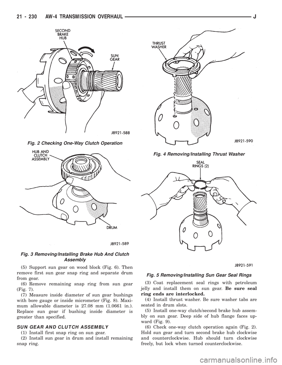
(1) Hold sun gear and turn second brake hub
clockwise and counterclockwise (Fig. 2). Hub should
rotate freely clockwise but lock when turned counter-clockwise. Replace one-way clutch and hub if they do
not operate properly.
(2) Remove one-way clutch/second brake hub as-
sembly from drum (Fig. 3).
(3) Remove thrust washer from drum (Fig. 4).
(4) Remove two seal rings from sun gear (Fig. 5).
Fig. 1 Sun Gear And One-Way Clutch Components
Fig. 3 Installing Front Planetary Thrust Race
Fig. 4 Installing Front Planetary Front Bearing And
Races
JAW-4 TRANSMISSION OVERHAUL 21 - 229
Page 1341 of 1784

(5) Support sun gear on wood block (Fig. 6). Then
remove first sun gear snap ring and separate drum
from gear.
(6) Remove remaining snap ring from sun gear
(Fig. 7).
(7) Measure inside diameter of sun gear bushings
with bore gauge or inside micrometer (Fig. 8). Maxi-
mum allowable diameter is 27.08 mm (1.0661 in.).
Replace sun gear if bushing inside diameter is
greater than specified.
SUN GEAR AND CLUTCH ASSEMBLY
(1) Install first snap ring on sun gear.
(2) Install sun gear in drum and install remaining
snap ring.(3) Coat replacement seal rings with petroleum
jelly and install them on sun gear.Be sure seal
ring ends are interlocked.
(4) Install thrust washer. Be sure washer tabs are
seated in drum slots.
(5) Install one-way clutch/second brake hub assem-
bly on sun gear. Deep side of hub flange faces up-
ward (Fig. 9).
(6) Check one-way clutch operation again (Fig. 2).
Hold sun gear and turn second brake hub clockwise
and counterclockwise. Hub should turn clockwise
freely, but lock when turned counterclockwise.
Fig. 2 Checking One-Way Clutch Operation
Fig. 3 Removing/Installing Brake Hub And Clutch
Assembly
Fig. 4 Removing/Installing Thrust Washer
Fig. 5 Removing/Installing Sun Gear Seal Rings
21 - 230 AW-4 TRANSMISSION OVERHAULJ