Page 1495 of 1784
DOOR REMOVAL/INSTALLATION
REMOVAL
(1) Remove the door restraint (check) retaining pin
(Fig. 24) with a punch.
(2) For vehicles equipped with power windows and
power door locks, remove the trim panel and discon-
nect all components. Slide the wire harness out of
the boot and door.
(3) Remove the door hinge bolts, plates and shims
(Fig. 30). Remove the door from the vehicle.
(4) Identify and retain the door hinge plates and
the shims for correct installation (Fig. 30).
Fig. 24 Door Restraint Retaining Pin
Fig. 25 XJ Right Front Door Wire Harness
Connectors
Fig. 26 XJ Right Front Door Wire Harness
ConnectorsÐWith Security Alarm Switch
Fig. 27 XJ Left Front Door Wire Harness Connectors
23 - 40 BODY COMPONENTSÐXJ VEHICLESJ
Page 1509 of 1784

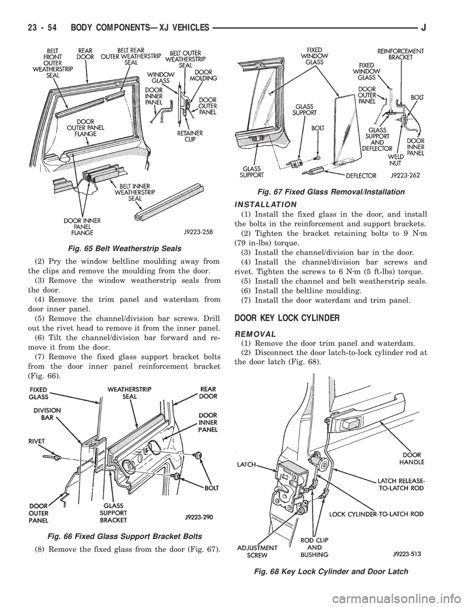
(2) Pry the window beltline moulding away from
the clips and remove the moulding from the door.
(3) Remove the window weatherstrip seals from
the door.
(4) Remove the trim panel and waterdam from
door inner panel.
(5) Remove the channel/division bar screws. Drill
out the rivet head to remove it from the inner panel.
(6) Tilt the channel/division bar forward and re-
move it from the door.
(7) Remove the fixed glass support bracket bolts
from the door inner panel reinforcement bracket
(Fig. 66).
(8) Remove the fixed glass from the door (Fig. 67).
INSTALLATION
(1) Install the fixed glass in the door, and install
the bolts in the reinforcement and support brackets.
(2) Tighten the bracket retaining bolts to 9 Nzm
(79 in-lbs) torque.
(3) Install the channel/division bar in the door.
(4) Install the channel/division bar screws and
rivet. Tighten the screws to 6 Nzm (5 ft-lbs) torque.
(5) Install the channel and belt weatherstrip seals.
(6) Install the beltline moulding.
(7) Install the door waterdam and trim panel.
DOOR KEY LOCK CYLINDER
REMOVAL
(1) Remove the door trim panel and waterdam.
(2) Disconnect the door latch-to-lock cylinder rod at
the door latch (Fig. 68).
Fig. 67 Fixed Glass Removal/Installation
Fig. 65 Belt Weatherstrip Seals
Fig. 66 Fixed Glass Support Bracket Bolts
Fig. 68 Key Lock Cylinder and Door Latch
23 - 54 BODY COMPONENTSÐXJ VEHICLESJ
Page 1510 of 1784

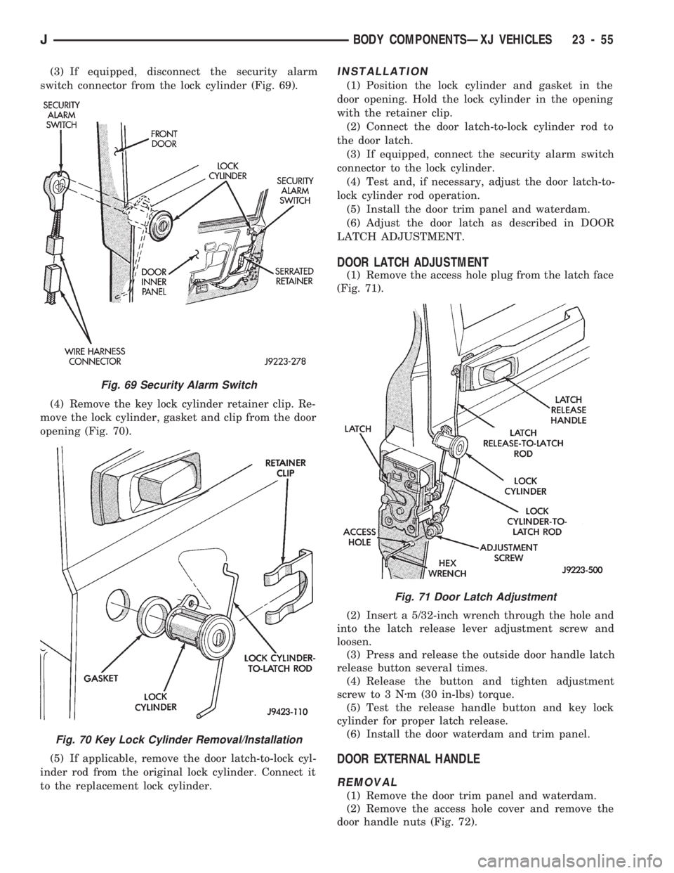
(3) If equipped, disconnect the security alarm
switch connector from the lock cylinder (Fig. 69).
(4) Remove the key lock cylinder retainer clip. Re-
move the lock cylinder, gasket and clip from the door
opening (Fig. 70).
(5) If applicable, remove the door latch-to-lock cyl-
inder rod from the original lock cylinder. Connect it
to the replacement lock cylinder.INSTALLATION
(1) Position the lock cylinder and gasket in the
door opening. Hold the lock cylinder in the opening
with the retainer clip.
(2) Connect the door latch-to-lock cylinder rod to
the door latch.
(3) If equipped, connect the security alarm switch
connector to the lock cylinder.
(4) Test and, if necessary, adjust the door latch-to-
lock cylinder rod operation.
(5) Install the door trim panel and waterdam.
(6) Adjust the door latch as described in DOOR
LATCH ADJUSTMENT.
DOOR LATCH ADJUSTMENT
(1) Remove the access hole plug from the latch face
(Fig. 71).
(2) Insert a 5/32-inch wrench through the hole and
into the latch release lever adjustment screw and
loosen.
(3) Press and release the outside door handle latch
release button several times.
(4) Release the button and tighten adjustment
screw to 3 Nzm (30 in-lbs) torque.
(5) Test the release handle button and key lock
cylinder for proper latch release.
(6) Install the door waterdam and trim panel.
DOOR EXTERNAL HANDLE
REMOVAL
(1) Remove the door trim panel and waterdam.
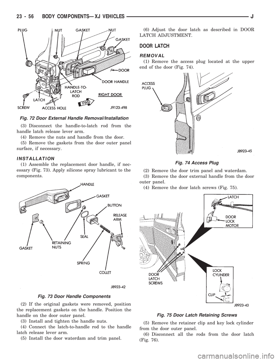
(2) Remove the access hole cover and remove the
door handle nuts (Fig. 72).
Fig. 71 Door Latch Adjustment
Fig. 69 Security Alarm Switch
Fig. 70 Key Lock Cylinder Removal/Installation
JBODY COMPONENTSÐXJ VEHICLES 23 - 55
Page 1511 of 1784

(3) Disconnect the handle-to-latch rod from the
handle latch release lever arm.
(4) Remove the nuts and handle from the door.
(5) Remove the gaskets from the door outer panel
surface, if necessary.
INSTALLATION
(1) Assemble the replacement door handle, if nec-
essary (Fig. 73). Apply silicone spray lubricant to the
components.
(2) If the original gaskets were removed, position
the replacement gaskets on the handle. Position the
handle on the door outer panel.
(3) Install and tighten the handle nuts.
(4) Connect the latch-to-handle rod to the handle
latch release lever arm.
(5) Install the door waterdam and trim panel.(6) Adjust the door latch as described in DOOR
LATCH ADJUSTMENT.
DOOR LATCH
REMOVAL
(1) Remove the access plug located at the upper
end of the door (Fig. 74).
(2) Remove the door trim panel and waterdam.
(3) Remove the door external handle from the door
outer panel.
(4) Remove the door latch screws (Fig. 75).
(5) Remove the retainer clip and key lock cylinder
from the door outer panel.
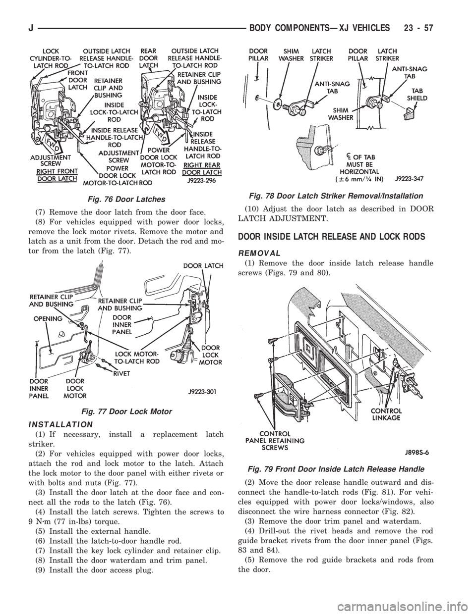
(6) Disconnect all the rods from the door latch
(Fig. 76).
Fig. 72 Door External Handle Removal/Installation
Fig. 73 Door Handle Components
Fig. 74 Access Plug
Fig. 75 Door Latch Retaining Screws
23 - 56 BODY COMPONENTSÐXJ VEHICLESJ
Page 1512 of 1784

(7) Remove the door latch from the door face.
(8) For vehicles equipped with power door locks,
remove the lock motor rivets. Remove the motor and
latch as a unit from the door. Detach the rod and mo-
tor from the latch (Fig. 77).
INSTALLATION
(1) If necessary, install a replacement latch
striker.
(2) For vehicles equipped with power door locks,
attach the rod and lock motor to the latch. Attach
the lock motor to the door panel with either rivets or
with bolts and nuts (Fig. 77).
(3) Install the door latch at the door face and con-
nect all the rods to the latch (Fig. 76).
(4) Install the latch screws. Tighten the screws to
9Nzm (77 in-lbs) torque.
(5) Install the external handle.
(6) Install the latch-to-door handle rod.
(7) Install the key lock cylinder and retainer clip.
(8) Install the door waterdam and trim panel.
(9) Install the door access plug.(10) Adjust the door latch as described in DOOR
LATCH ADJUSTMENT.
DOOR INSIDE LATCH RELEASE AND LOCK RODS
REMOVAL
(1) Remove the door inside latch release handle
screws (Figs. 79 and 80).
(2) Move the door release handle outward and dis-
connect the handle-to-latch rods (Fig. 81). For vehi-
cles equipped with power door locks/windows, also
disconnect the wire harness connector (Fig. 82).
(3) Remove the door trim panel and waterdam.
(4) Drill-out the rivet heads and remove the rod
guide bracket rivets from the door inner panel (Figs.
83 and 84).
(5) Remove the rod guide brackets and rods from
the door.
Fig. 76 Door Latches
Fig. 77 Door Lock Motor
Fig. 78 Door Latch Striker Removal/Installation
Fig. 79 Front Door Inside Latch Release Handle
JBODY COMPONENTSÐXJ VEHICLES 23 - 57
Page 1515 of 1784
92). Be careful not to bend the hinge when driving
the hinge pin, support may be required under the
hinge.
(8) Adjust/align latch striker and latch as neces-
sary.(9) Install the door restraint (check) retaining pin
with a punch.
FRONT DOOR SPACER BLOCKSÐTWO-DOOR
VEHICLES
REMOVAL
(1) Upper spacer block: drill-out the rivet heads
and remove them from the reinforcement plate
(Fig.93).
(2) Lower spacer block: remove the screws from the
door face Fig. 94).
(3) As applicable, remove the spacer block from the
door window frame or door face.
INSTALLATION
(1) As applicable, position the spacer block on the
door window frame or door face.
(2) Upper spacer block: Install the replacement riv-
ets in the spacer block and reinforcement plate.
Fig 89 Install Bushing In Hinge
Fig. 90 Begin To Roll Bushing Material Outward
Fig. 91 Forming A Head On The Bushing
Fig. 92 Installing The Hinge Pin
Fig. 93 Front Door Upper Spacer BlockÐTwo-Door
Vehicles
23 - 60 BODY COMPONENTSÐXJ VEHICLESJ
Page 1516 of 1784
(3) Lower spacer block: install the screws in the
door face. Tighten the screws to 1 Nzm (11 in-lbs)
torque.
DOOR EDGE GUARD/EDGE PROTECTOR STRIP
REPLACEMENT
(1) Pull outward and remove the door edge guard
strip from the door edge (Fig. 95).
(2) Position the door edge guard strip on the door
edge.
(3) Force the door edge guard strip inward until it
is seated on the door edge.
DOOR WINDOW EXTERIOR MOULDINGS
REMOVAL
(1) When removing the front or rear door window
exterior moulding, open the window completely (Figs.
96 and 97).
(2) Pry and pull the moulding sections from the
door panel flange and clips.
Fig. 95 Door Edge Guard/Protector Strip
Fig. 96 Front Door Window Exterior Moulding
Fig. 94 Front Door Lower Spacer BlockÐTwo-Door
Vehicles
JBODY COMPONENTSÐXJ VEHICLES 23 - 61
Page 1523 of 1784
(2) Install and tighten hinge-to-roof panel nuts to 9
Nzm (7 ft-lbs) torque.
(3) Install the liftgate-to-hinge screws. Tighten
screws to 9 Nzm (7 ft-lbs) torque.
(4) Install the liftgate (headliner) upper trim moul-
ding (Fig. 111).
LIFTGATE LATCH/KEY LOCK CYLINDER/STRIKER
REMOVAL
(1) Raise the liftgate and remove the latch screws
(Fig. 120).
(2) Disconnect the rod from the latch (Fig. 121).(3) Remove the latch from the liftgate (Fig. 122).
(4) Drill-out the rivet heads and remove the lock
solenoid from liftgate (Fig. 123).
(5) Remove the lock cylinder retainer clip (Fig. 124).
Fig. 121 Latch and Key Lock Cylinder
Fig. 122 Liftgate Latch and Solenoid
Fig. 123 Liftgate Lock Solenoid
Fig. 124 Liftgate Key Lock Cylinder
Fig. 120 Liftgate Latch Screws
23 - 68 BODY COMPONENTSÐXJ VEHICLESJ