1994 JEEP CHEROKEE lock
[x] Cancel search: lockPage 1630 of 1784
(6) Install the interior trim panel (Fig. 4).
(7) Connect the latch release rod to the door latch
interior release handle and install the handle (Fig.
4).
(8) Install the assist handle (Fig. 4).
(9) Install the window retaining sleeves (Fig. 2).
(10) Install the window (Fig. 1).
(11) Attach the restraint strap to the pin (Fig. 1).
HALF-METAL DOOR LATCH STRIKER
REPLACEMENT
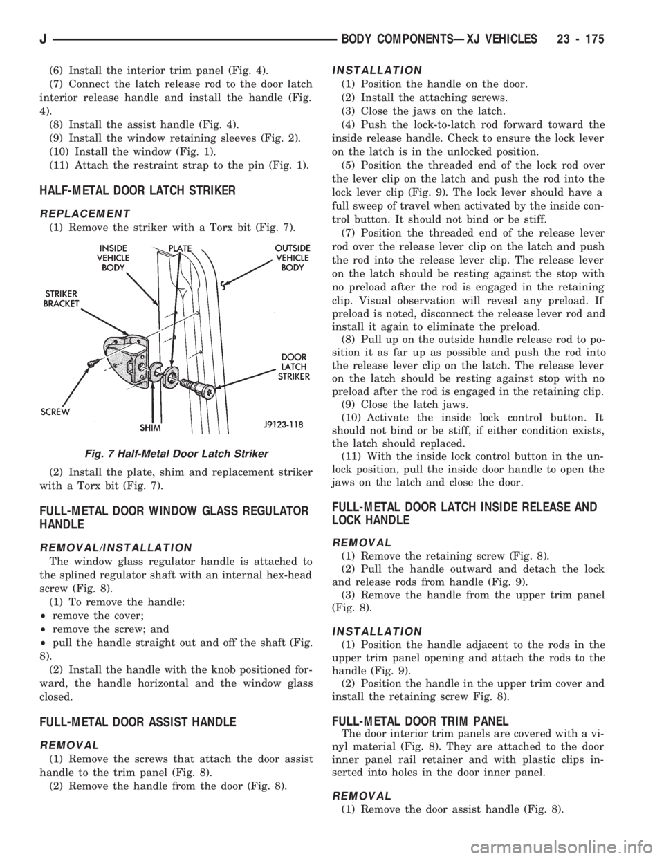
(1) Remove the striker with a Torx bit (Fig. 7).
(2) Install the plate, shim and replacement striker
with a Torx bit (Fig. 7).
FULL-METAL DOOR WINDOW GLASS REGULATOR
HANDLE
REMOVAL/INSTALLATION
The window glass regulator handle is attached to
the splined regulator shaft with an internal hex-head
screw (Fig. 8).
(1) To remove the handle:
²remove the cover;
²remove the screw; and
²pull the handle straight out and off the shaft (Fig.
8).
(2) Install the handle with the knob positioned for-
ward, the handle horizontal and the window glass
closed.
FULL-METAL DOOR ASSIST HANDLE
REMOVAL
(1) Remove the screws that attach the door assist
handle to the trim panel (Fig. 8).
(2) Remove the handle from the door (Fig. 8).
INSTALLATION
(1) Position the handle on the door.
(2) Install the attaching screws.
(3) Close the jaws on the latch.
(4) Push the lock-to-latch rod forward toward the
inside release handle. Check to ensure the lock lever
on the latch is in the unlocked position.
(5) Position the threaded end of the lock rod over
the lever clip on the latch and push the rod into the
lock lever clip (Fig. 9). The lock lever should have a
full sweep of travel when activated by the inside con-
trol button. It should not bind or be stiff.
(7) Position the threaded end of the release lever
rod over the release lever clip on the latch and push
the rod into the release lever clip. The release lever
on the latch should be resting against the stop with
no preload after the rod is engaged in the retaining
clip. Visual observation will reveal any preload. If
preload is noted, disconnect the release lever rod and
install it again to eliminate the preload.
(8) Pull up on the outside handle release rod to po-
sition it as far up as possible and push the rod into
the release lever clip on the latch. The release lever
on the latch should be resting against stop with no
preload after the rod is engaged in the retaining clip.
(9) Close the latch jaws.
(10) Activate the inside lock control button. It
should not bind or be stiff, if either condition exists,
the latch should replaced.
(11) With the inside lock control button in the un-
lock position, pull the inside door handle to open the
jaws on the latch and close the door.
FULL-METAL DOOR LATCH INSIDE RELEASE AND
LOCK HANDLE
REMOVAL
(1) Remove the retaining screw (Fig. 8).
(2) Pull the handle outward and detach the lock
and release rods from handle (Fig. 9).
(3) Remove the handle from the upper trim panel
(Fig. 8).
INSTALLATION
(1) Position the handle adjacent to the rods in the
upper trim panel opening and attach the rods to the
handle (Fig. 9).
(2) Position the handle in the upper trim cover and
install the retaining screw Fig. 8).
FULL-METAL DOOR TRIM PANEL
The door interior trim panels are covered with a vi-
nyl material (Fig. 8). They are attached to the door
inner panel rail retainer and with plastic clips in-
serted into holes in the door inner panel.
REMOVAL
(1) Remove the door assist handle (Fig. 8).
Fig. 7 Half-Metal Door Latch Striker
JBODY COMPONENTSÐXJ VEHICLES 23 - 175
Page 1633 of 1784
(6) Install the door waterdam and the trim panel
(Figs. 8 and 10).
FULL-METAL DOOR WINDOW GLASS
ADJUSTMENT
One adjustment location provides amount of effort
required to raise and lower the door window glass.
The door window glass division channel is adjustable
fore and aft at the lower attaching location.
(1) Remove the door trim panel and the waterdam
(Figs. 8 and 10).
(2) Loosen channel lower adjustment screw and
move the division channel fore or aft to obtain the
desired door window glass operation.
Movement of the division channel fore or aft
will decrease or increase the free-play between
the channels.
(3) Tighten the division channel lower adjustment
screw.
(4) Install the door waterdam and the trim panel
(Figs. 8 and 10).
REMOVAL
(1) Remove the door trim panel and the waterdam
(Figs. 8 and 10).
(2) Remove the window glass down-stop bumper
(Fig. 11).
(3) Remove the screws that attach the regulator
arm guide to the window glass. Remove the screws,
bushings, nuts and the guide from the glass (Fig. 11).
(4) Lower the window glass to the bottom of the
door.
(5) Remove the division channel upper attaching
screw and the lower adjustment screw. Detach the
front 3 inches of window glass weatherstrip seal from
the door upper frame.
(6) Separate the division channel from the front
window glass rubber seal. Pull the division channel
up and in toward the inside of vehicle.
(7) Raise and tilt the window glass toward the
hinge side of the door and disengage it from the rear
channel.
(8) Pull the window glass up and out of the door
panel.
INSTALLATION
(1) Lower the window glass into the door, while in-
serting the window glass into the front and rear
channels.
(2) Slide the window glass downward to the bottom
of the door panel.
(3) Lower the division channel into the door and
position the window glass securely in the channel.
(4) Install the weatherstrip seal in the upper door
frame and install the upper attaching screw and the
lower adjustment screw.(5) Slide the guide onto the regulator arm and po-
sition the guide on the window glass. Install the re-
taining nuts, bushings and screws (Fig. 12).
(6) Install the window glass down-stop bumper
(Fig. 11).
(7) Test the window operation for proper adjust-
ment.
(8) Install the door waterdam and the trim panel
(Fig. 8 and 10).
FULL-METAL DOOR KEY LOCK CYLINDER
REMOVAL
(1) Remove the door trim panel and the waterdam
(Figs. 8 and 10).
(2) Remove the door latch cover screws and remove
the cover (Fig. 11).
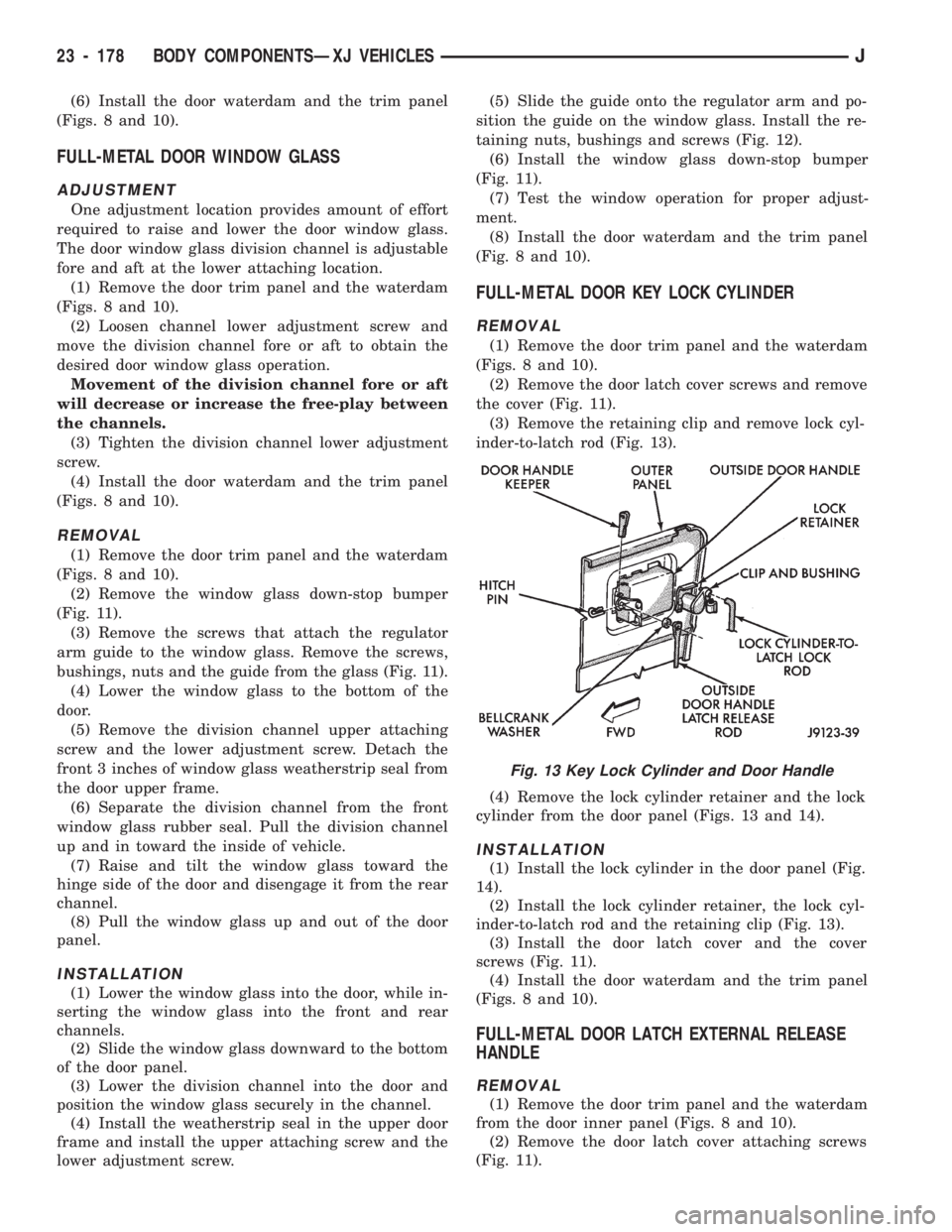
(3) Remove the retaining clip and remove lock cyl-
inder-to-latch rod (Fig. 13).
(4) Remove the lock cylinder retainer and the lock
cylinder from the door panel (Figs. 13 and 14).
INSTALLATION
(1) Install the lock cylinder in the door panel (Fig.
14).
(2) Install the lock cylinder retainer, the lock cyl-
inder-to-latch rod and the retaining clip (Fig. 13).
(3) Install the door latch cover and the cover
screws (Fig. 11).
(4) Install the door waterdam and the trim panel
(Figs. 8 and 10).
FULL-METAL DOOR LATCH EXTERNAL RELEASE
HANDLE
REMOVAL
(1) Remove the door trim panel and the waterdam
from the door inner panel (Figs. 8 and 10).
(2) Remove the door latch cover attaching screws
(Fig. 11).
Fig. 13 Key Lock Cylinder and Door Handle
23 - 178 BODY COMPONENTSÐXJ VEHICLESJ
Page 1634 of 1784
(3) Remove the hitch pin and the latch release rod
from the door external handle (Fig. 13).
(4) Close the window completely and tap the han-
dle keepers upward (Fig. 13).
(5) Disconnect the window glass from the regulator
arm guide (Fig. 12).
(6) Remove the division channel upper and lower
attaching screws.
(7) Separate the division channel from the front
window glass weatherstrip seal.
(8) Pull the division channel upward and remove
the window glass from the door.
(9) Remove the keepers from the door handle with
needlenose pliers and remove the handle and gasket
from the door (Figs. 13 and 14).
INSTALLATION
(1) Install the gasket and the door external handle
and slide the keepers into the door handle from the
top (Figs. 13 and 14).
(2) Tap the retainers downward lightly to tighten
the handle.
(3) Install the latch release rod and the hitch pin
and attach the rod to the latch (Fig. 13).
(4) Position the window glass in the door and the
channels.
(5) Install the division channel and the attaching
screws.
(6) Attach the window glass to the regulator arm
guide (Fig. 12).
(7) Install the door latch cover (Fig. 11).
(8) Install the door waterdam and the trim panel
(Figs. 8 and 10).
FULL-METAL DOOR LATCH
REMOVAL
(1) Remove the trim panel and the waterdam from
the door inner panel (Figs. 8 and 10) .
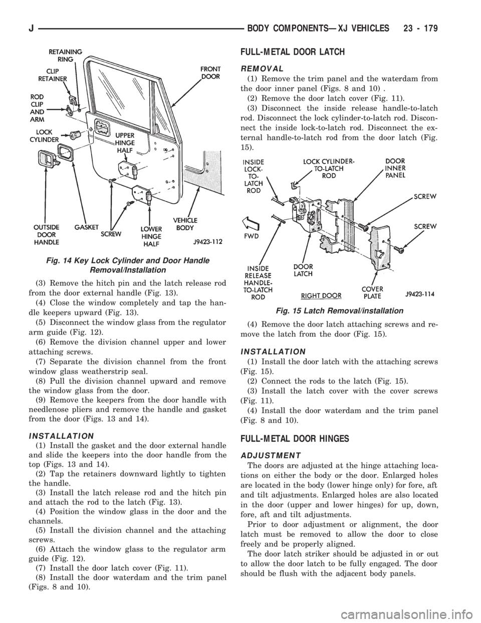
(2) Remove the door latch cover (Fig. 11).
(3) Disconnect the inside release handle-to-latch
rod. Disconnect the lock cylinder-to-latch rod. Discon-
nect the inside lock-to-latch rod. Disconnect the ex-
ternal handle-to-latch rod from the door latch (Fig.
15).
(4) Remove the door latch attaching screws and re-
move the latch from the door (Fig. 15).
INSTALLATION
(1) Install the door latch with the attaching screws
(Fig. 15).
(2) Connect the rods to the latch (Fig. 15).
(3) Install the latch cover with the cover screws
(Fig. 11).
(4) Install the door waterdam and the trim panel
(Fig. 8 and 10).
FULL-METAL DOOR HINGES
ADJUSTMENT
The doors are adjusted at the hinge attaching loca-
tions on either the body or the door. Enlarged holes
are located in the body (lower hinge only) for fore, aft
and tilt adjustments. Enlarged holes are also located
in the door (upper and lower hinges) for up, down,
fore, aft and tilt adjustments.
Prior to door adjustment or alignment, the door
latch must be removed to allow the door to close
freely and be properly aligned.
The door latch striker should be adjusted in or out
to allow the door latch to be fully engaged. The door
should be flush with the adjacent body panels.
Fig. 15 Latch Removal/installation
Fig. 14 Key Lock Cylinder and Door Handle
Removal/Installation
JBODY COMPONENTSÐXJ VEHICLES 23 - 179
Page 1636 of 1784
INSTALLATION
(1) Apply adhesive to the front, rear and bottom
edges of the door from the beltline downward.
(2) Install the upper front corner of the seal on the
door first using your fingers or a wooden wand to po-
sition the seal in the channel. Place the inner shoul-
der of the seal in the channel-to-window frame above
the beltline.
(3) Force the retainers, starting at the rear edge of
the door, into the door panel holes.
(4) Ensure that the seal is completely seated
around the door.
BELTLINE SEAL REPLACEMENT
REMOVAL
(1) Carefully remove the beltline weatherstrip seal
(Fig. 17) from the door with a weatherstrip seal re-
moval tool or similar pry tool.
(2) Pry the seal upward to remove it from within
the glass and door panel.
INSTALLATION
(1) Position the seal between the door panel and
the glass. Force the seal downward with your fingers
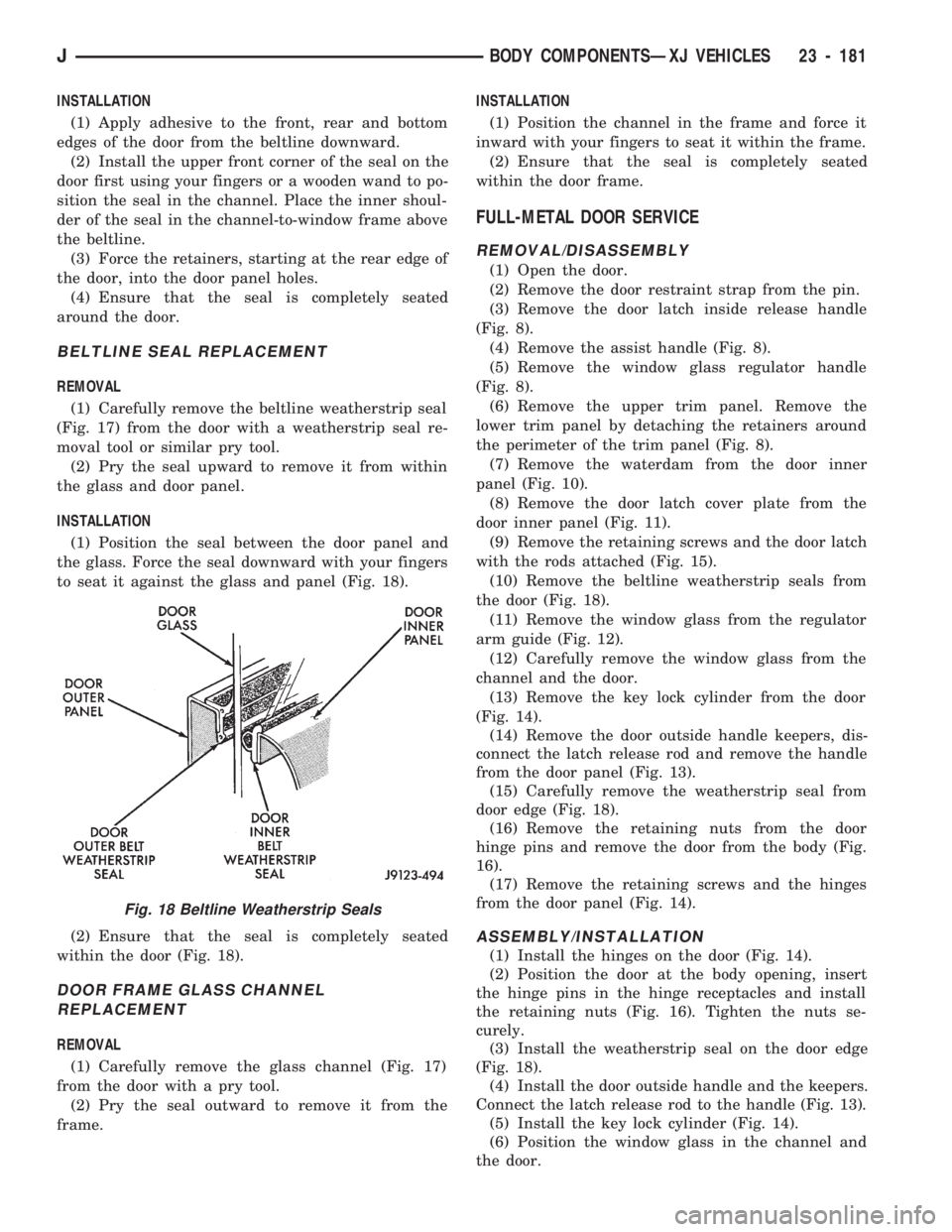
to seat it against the glass and panel (Fig. 18).
(2) Ensure that the seal is completely seated
within the door (Fig. 18).
DOOR FRAME GLASS CHANNEL
REPLACEMENT
REMOVAL
(1) Carefully remove the glass channel (Fig. 17)
from the door with a pry tool.
(2) Pry the seal outward to remove it from the
frame.INSTALLATION
(1) Position the channel in the frame and force it
inward with your fingers to seat it within the frame.
(2) Ensure that the seal is completely seated
within the door frame.
FULL-METAL DOOR SERVICE
REMOVAL/DISASSEMBLY
(1) Open the door.
(2) Remove the door restraint strap from the pin.
(3) Remove the door latch inside release handle
(Fig. 8).
(4) Remove the assist handle (Fig. 8).
(5) Remove the window glass regulator handle
(Fig. 8).
(6) Remove the upper trim panel. Remove the
lower trim panel by detaching the retainers around
the perimeter of the trim panel (Fig. 8).
(7) Remove the waterdam from the door inner
panel (Fig. 10).
(8) Remove the door latch cover plate from the
door inner panel (Fig. 11).
(9) Remove the retaining screws and the door latch
with the rods attached (Fig. 15).
(10) Remove the beltline weatherstrip seals from
the door (Fig. 18).
(11) Remove the window glass from the regulator
arm guide (Fig. 12).
(12) Carefully remove the window glass from the
channel and the door.
(13) Remove the key lock cylinder from the door
(Fig. 14).
(14) Remove the door outside handle keepers, dis-
connect the latch release rod and remove the handle
from the door panel (Fig. 13).
(15) Carefully remove the weatherstrip seal from
door edge (Fig. 18).
(16) Remove the retaining nuts from the door
hinge pins and remove the door from the body (Fig.
16).
(17) Remove the retaining screws and the hinges
from the door panel (Fig. 14).
ASSEMBLY/INSTALLATION
(1) Install the hinges on the door (Fig. 14).
(2) Position the door at the body opening, insert
the hinge pins in the hinge receptacles and install
the retaining nuts (Fig. 16). Tighten the nuts se-
curely.
(3) Install the weatherstrip seal on the door edge
(Fig. 18).
(4) Install the door outside handle and the keepers.
Connect the latch release rod to the handle (Fig. 13).
(5) Install the key lock cylinder (Fig. 14).
(6) Position the window glass in the channel and
the door.
Fig. 18 Beltline Weatherstrip Seals
JBODY COMPONENTSÐXJ VEHICLES 23 - 181
Page 1637 of 1784
(7) Attach the window glass to the regulator arm
guide (Fig. 12).
(8) Install the beltline weatherstrip seals in the
door (Fig. 18).
(9) Position the latch in the door and install the re-
taining screws (Fig. 15). Tighten the screws securely.
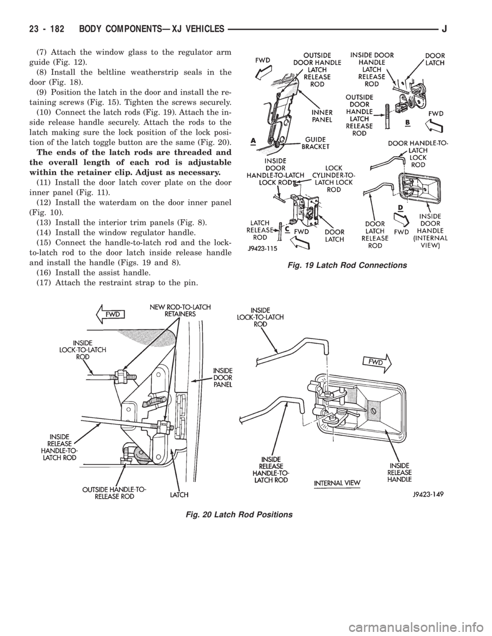
(10) Connect the latch rods (Fig. 19). Attach the in-
side release handle securely. Attach the rods to the
latch making sure the lock position of the lock posi-
tion of the latch toggle button are the same (Fig. 20).
The ends of the latch rods are threaded and
the overall length of each rod is adjustable
within the retainer clip. Adjust as necessary.
(11) Install the door latch cover plate on the door
inner panel (Fig. 11).
(12) Install the waterdam on the door inner panel
(Fig. 10).
(13) Install the interior trim panels (Fig. 8).
(14) Install the window regulator handle.
(15) Connect the handle-to-latch rod and the lock-
to-latch rod to the door latch inside release handle
and install the handle (Figs. 19 and 8).
(16) Install the assist handle.
(17) Attach the restraint strap to the pin.
Fig. 20 Latch Rod Positions
Fig. 19 Latch Rod Connections
23 - 182 BODY COMPONENTSÐXJ VEHICLESJ
Page 1650 of 1784
(3) If necessary, remove the retaining screws and
the hinge from the glove box door.
INSTALLATION
(1) If removed, install the hinge on the glove box
door with screws. Tighten the screws securely.
(2) Position the glove box door and hinge on the
glove box housing.
(3) Install the hinge-to-glove box housing screws
and adjust the door for proper fit within the opening.
Tighten the screws securely.
DOOR LATCH STRIKER ADJUSTMENT
The glove box door lock cylinder latch striker is at-
tached to the glove box housing opening with screws.
The striker can be moved in or out for adjustment.
SEATS
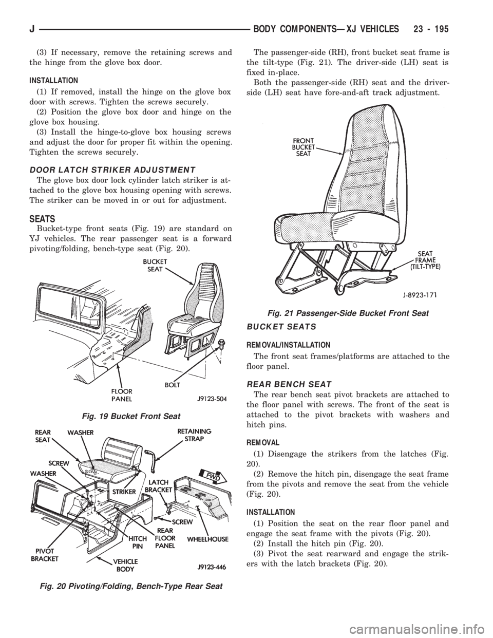
Bucket-type front seats (Fig. 19) are standard on
YJ vehicles. The rear passenger seat is a forward
pivoting/folding, bench-type seat (Fig. 20).The passenger-side (RH), front bucket seat frame is
the tilt-type (Fig. 21). The driver-side (LH) seat is
fixed in-place.
Both the passenger-side (RH) seat and the driver-
side (LH) seat have fore-and-aft track adjustment.
BUCKET SEATS
REMOVAL/INSTALLATION
The front seat frames/platforms are attached to the
floor panel.
REAR BENCH SEAT
The rear bench seat pivot brackets are attached to
the floor panel with screws. The front of the seat is
attached to the pivot brackets with washers and
hitch pins.
REMOVAL
(1) Disengage the strikers from the latches (Fig.
20).
(2) Remove the hitch pin, disengage the seat frame
from the pivots and remove the seat from the vehicle
(Fig. 20).
INSTALLATION
(1) Position the seat on the rear floor panel and
engage the seat frame with the pivots (Fig. 20).
(2) Install the hitch pin (Fig. 20).
(3) Pivot the seat rearward and engage the strik-
ers with the latch brackets (Fig. 20).
Fig. 19 Bucket Front Seat
Fig. 20 Pivoting/Folding, Bench-Type Rear Seat
Fig. 21 Passenger-Side Bucket Front Seat
JBODY COMPONENTSÐXJ VEHICLES 23 - 195
Page 1652 of 1784
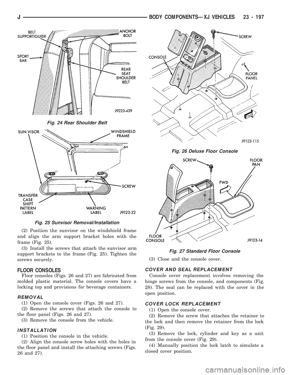
(2) Position the sunvisor on the windshield frame
and align the arm support bracket holes with the
frame (Fig. 25).
(3) Install the screws that attach the sunvisor arm
support brackets to the frame (Fig. 25). Tighten the
screws securely.
FLOOR CONSOLES
Floor consoles (Figs. 26 and 27) are fabricated from
molded plastic material. The console covers have a
locking top and provisions for beverage containers.
REMOVAL
(1) Open the console cover (Figs. 26 and 27).
(2) Remove the screws that attach the console to
the floor panel (Figs. 26 and 27).
(3) Remove the console from the vehicle.
INSTALLATION
(1) Position the console in the vehicle.
(2) Align the console screw holes with the holes in
the floor panel and install the attaching screws (Figs.
26 and 27).(3) Close and the console cover.
COVER AND SEAL REPLACEMENT
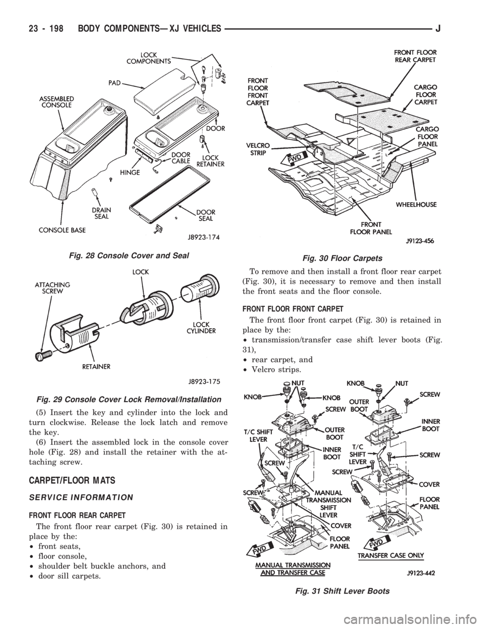
Console cover replacement involves removing the
hinge screws from the console, and components (Fig.
28). The seal can be replaced with the cover in the
open position.
COVER LOCK REPLACEMENT
(1) Open the console cover.
(2) Remove the screw that attaches the retainer to
the lock and then remove the retainer from the lock
(Fig. 29).
(3) Remove the lock, cylinder and key as a unit
from the console cover (Fig. 29).
(4) Manually position the lock latch to simulate a
closed cover position.
Fig. 24 Rear Shoulder Belt
Fig. 25 Sunvisor Removal/Installation
Fig. 26 Deluxe Floor Console
Fig. 27 Standard Floor Console
JBODY COMPONENTSÐXJ VEHICLES 23 - 197
Page 1653 of 1784
(5) Insert the key and cylinder into the lock and
turn clockwise. Release the lock latch and remove
the key.
(6) Insert the assembled lock in the console cover
hole (Fig. 28) and install the retainer with the at-
taching screw.
CARPET/FLOOR MATS
SERVICE INFORMATION
FRONT FLOOR REAR CARPET
The front floor rear carpet (Fig. 30) is retained in
place by the:
²front seats,
²floor console,
²shoulder belt buckle anchors, and
²door sill carpets.To remove and then install a front floor rear carpet
(Fig. 30), it is necessary to remove and then install
the front seats and the floor console.
FRONT FLOOR FRONT CARPET
The front floor front carpet (Fig. 30) is retained in
place by the:
²transmission/transfer case shift lever boots (Fig.
31),
²rear carpet, and
²Velcro strips.
Fig. 28 Console Cover and Seal
Fig. 29 Console Cover Lock Removal/Installation
Fig. 30 Floor Carpets
Fig. 31 Shift Lever Boots
23 - 198 BODY COMPONENTSÐXJ VEHICLESJ