Page 1417 of 1784

Inspect the differential gears, thrust washers and
case halves. Replace the mainshaft gear if the gear
teeth or the brass ring on the underside of the gear
are damaged. Replace the differential as an assembly
if the gears, case halves, or the pins in the lower case
half are damaged.
Inspect the case halves, extension housing and re-
tainers for cracks, porosity, or damaged sealing sur-
faces. Inspect the shafts, gears, chain and shift
components for wear or damage.
Inspect all of the transfer case bearings for wear,
roughness, pitting, or galling. Replace worn or dam-
aged bearings as outlined in the assembly section.
TRANSFER CASE ASSEMBLY
(1) Lubricate the transfer case components with
automatic transmission fluid or petroleum jelly
(where indicated) during assembly.
CAUTION: The bearing bores in various transfer
case components contain oil feed holes. Be sure re-
placement bearings do not block these feed holes.
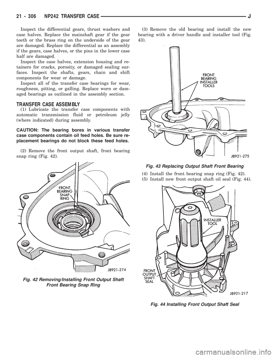
(2) Remove the front output shaft, front bearing
snap ring (Fig. 42).(3) Remove the old bearing and install the new
bearing with a driver handle and installer tool (Fig.
43).
(4) Install the front bearing snap ring (Fig. 42).
(5) Install new front output shaft oil seal (Fig. 44).
Fig. 42 Removing/Installing Front Output Shaft
Front Bearing Snap Ring
Fig. 43 Replacing Output Shaft Front Bearing
Fig. 44 Installing Front Output Shaft Seal
21 - 306 NP242 TRANSFER CASEJ
Page 1418 of 1784
(6) Press input gear bearing out of front case with
driver tool and shop press (Fig. 45).
(7) Install the snap ring on the new bearing.
(8) Install the new input gear bearing with a shop
press and wood block. Install the bearing far enough
to seat the snap ring against the case (Fig. 46).(9) Remove input gear pilot bearing with slide
hammer and internal puller (Fig. 47).
(10) Install new pilot bearing with driver tools
(Fig. 48).
Fig. 45 Removing Input Gear Bearing
Fig. 46 Seating Input Gear Bearing
Fig. 47 Removing Input Gear Pilot Bearing
Fig. 48 Installing Input Gear Pilot Bearing
JNP242 TRANSFER CASE 21 - 307
Page 1424 of 1784

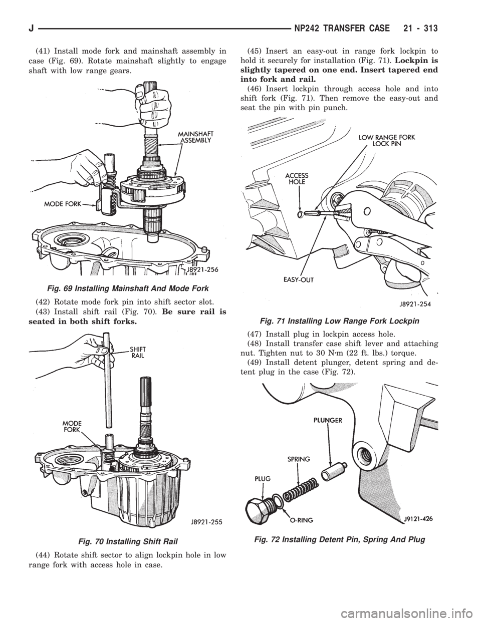
(41) Install mode fork and mainshaft assembly in
case (Fig. 69). Rotate mainshaft slightly to engage
shaft with low range gears.
(42) Rotate mode fork pin into shift sector slot.
(43) Install shift rail (Fig. 70).Be sure rail is
seated in both shift forks.
(44) Rotate shift sector to align lockpin hole in low
range fork with access hole in case.(45) Insert an easy-out in range fork lockpin to
hold it securely for installation (Fig. 71).Lockpin is
slightly tapered on one end. Insert tapered end
into fork and rail.
(46) Insert lockpin through access hole and into
shift fork (Fig. 71). Then remove the easy-out and
seat the pin with pin punch.
(47) Install plug in lockpin access hole.
(48) Install transfer case shift lever and attaching
nut. Tighten nut to 30 Nzm (22 ft. lbs.) torque.
(49) Install detent plunger, detent spring and de-
tent plug in the case (Fig. 72).
Fig. 69 Installing Mainshaft And Mode Fork
Fig. 70 Installing Shift Rail
Fig. 71 Installing Low Range Fork Lockpin
Fig. 72 Installing Detent Pin, Spring And Plug
JNP242 TRANSFER CASE 21 - 313
Page 1457 of 1784
KEY LOCK CYLINDERS
The ignition switch, glove box door, front doors and
liftgate all have key lock cylinders (Fig. 6). When
lock cylinder access or replacement is necessary, re-
fer to the applicable service information source:
²Ignition SwitchÐGroup 8D,
²Instrument Panel,
²Front Doors, and
²Liftgate.
Fig. 4 XJ VIN PlateFig. 5 XJ Jack Usage & Storage Instruction Labels
Fig. 6 Ignition Switch & Glove Box Door Key Lock
Cylinders
23 - 2 BODY COMPONENTSÐXJ VEHICLESJ
Page 1489 of 1784

DOORS
INDEX
page page
Door Alignment AdjustmentÐMajor........... 47
Door Alignment AdjustmentÐMinor........... 46
Door Edge Guard/Edge Protector Strip........ 61
Door External Handle..................... 55
Door Hinge/Hinge Pin Replacement........... 58
Door Inside Latch Release and Lock Rods..... 57
Door Key Lock Cylinder................... 54
Door Latch............................. 56
Door Latch Adjustment.................... 55
Door Removal/Installation.................. 40
Door Restraint Replacement................ 47
Door Trim Panel......................... 35
Door Window Exterior Mouldings............. 61
Door Window Glass and Door Opening
Weatherstrip Seals...................... 62
Front Door Spacer BlocksÐTwo-Door Vehicles . . 60
Front Door Vent Window................... 50
Front Door Window Glass.................. 49Front Door Window Glass Regulator.......... 48
Liftgate Adjustment....................... 70
Liftgate Hinge........................... 67
Liftgate Latch/Key Lock Cylinder/Striker........ 68
Liftgate License Plate Lamp Housing.......... 72
Liftgate License Plate Screw Anchor and Bumper . 72
Liftgate Opening Weatherstrip Seal........... 70
Liftgate Removal/Installation................ 65
Liftgate Service InformationÐXJ Vehicles...... 65
Liftgate Support Rod Ball Stud Replacement.... 70
Liftgate Support Rod Cylinder............... 69
Liftgate Support Rod Cylinder Disposal........ 70
Liftgate Trim Panel....................... 66
Rear Door Fixed Window Glass............. 53
Rear Door Window Glass.................. 52
Rear Door Window Glass Regulator.......... 51
Service Information....................... 34
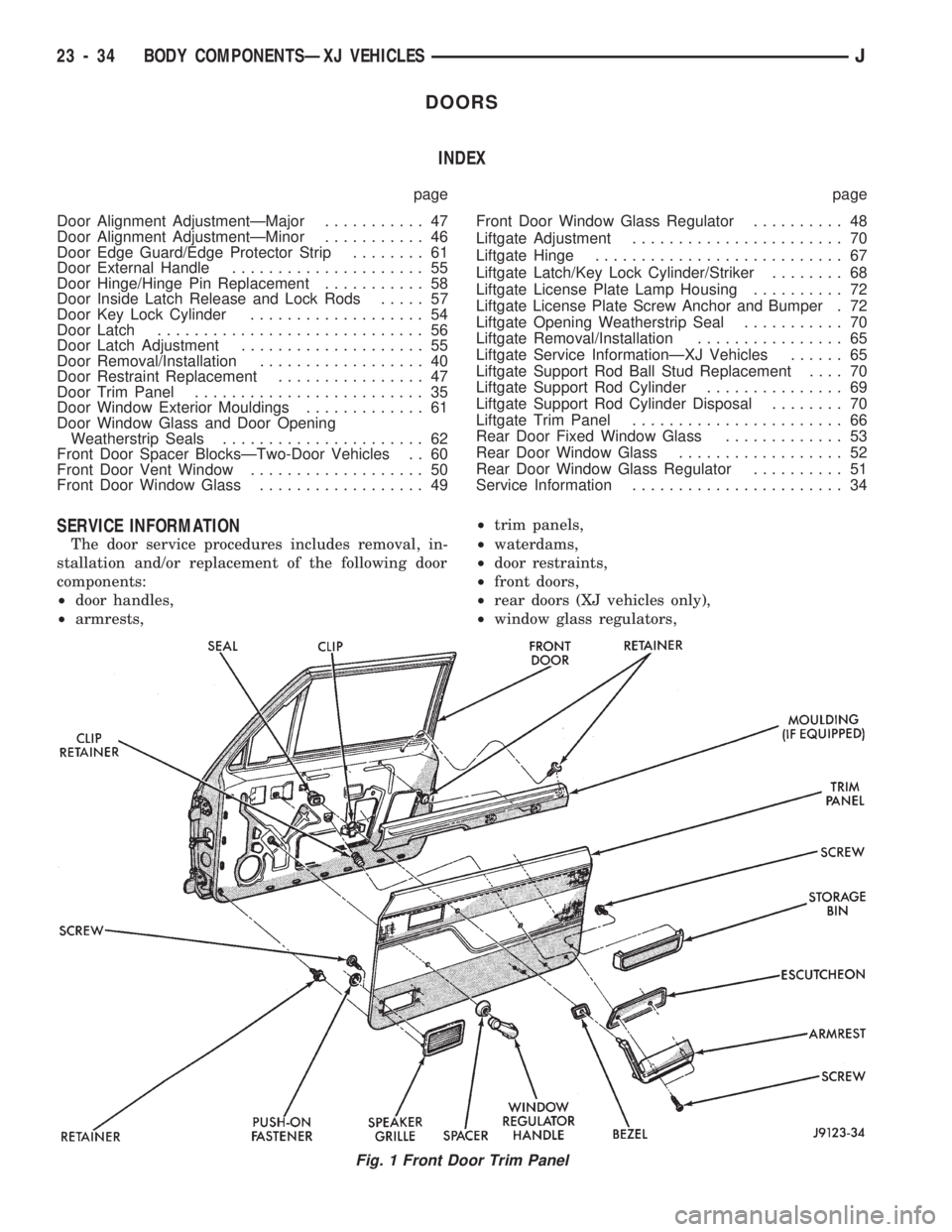
SERVICE INFORMATION
The door service procedures includes removal, in-
stallation and/or replacement of the following door
components:
²door handles,
²armrests,²trim panels,
²waterdams,
²door restraints,
²front doors,
²rear doors (XJ vehicles only),
²window glass regulators,
Fig. 1 Front Door Trim Panel
23 - 34 BODY COMPONENTSÐXJ VEHICLESJ
Page 1490 of 1784
²door vent and window glass,
²key lock cylinders,
²door half-hinges,
²liftgate (XJ vehicles only),
²liftgate hinges (XJ vehicles only),
²
liftgate gas support rod cylinders (XJ vehicles only),
²rocker panel seals, and
²mouldings/weatherstrip seals.
DOOR TRIM PANEL
SERVICE INFORMATION
All attached components can be removed from door
trim panels (Figs. 1 and 2).
REMOVAL
(1) Remove the door inside latch release handle
screws (Figs. 3 and 4).
(2) Move the door handle outward and disconnect
the handle-to-latch rods (Fig. 5). For vehicles
equipped with power door locks/windows, disconnect
the wire harness connector (Fig. 6).
(3) Remove the regulator handle (Fig. 7) or, if
equipped, power window switches and bezel.
(4) Remove the armrest lower screws.
(5) Pull armrest straight outward from panel and
remove the bezel.
Fig. 2 Rear Door Trim Panel
Fig. 3 Front Door Inside Latch Release Handle
Fig. 4 Rear Door Inside Latch Release Handle
JBODY COMPONENTSÐXJ VEHICLES 23 - 35
Page 1493 of 1784
(9) If necessary, remove the waterdam from the
door.
(10) If necessary, remove the storage bin panel and
speaker grille from the front door trim panel (Fig.
19).
Fig. 15 Front Door Waterdam
Fig. 16 Rear Door Waterdam
Fig. 17 Latch Release and Lock Rod Waterdam
Fig. 18 Power Switch Waterdam
Fig. 19 Storage Bin Panel and Speaker Grille
23 - 38 BODY COMPONENTSÐXJ VEHICLESJ
Page 1494 of 1784

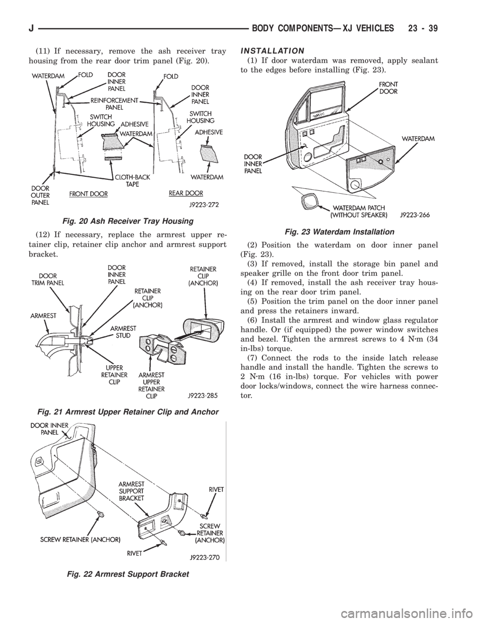
(11) If necessary, remove the ash receiver tray
housing from the rear door trim panel (Fig. 20).
(12) If necessary, replace the armrest upper re-
tainer clip, retainer clip anchor and armrest support
bracket.INSTALLATION
(1) If door waterdam was removed, apply sealant
to the edges before installing (Fig. 23).
(2) Position the waterdam on door inner panel
(Fig. 23).
(3) If removed, install the storage bin panel and
speaker grille on the front door trim panel.
(4) If removed, install the ash receiver tray hous-
ing on the rear door trim panel.
(5) Position the trim panel on the door inner panel
and press the retainers inward.
(6) Install the armrest and window glass regulator
handle. Or (if equipped) the power window switches
and bezel. Tighten the armrest screws to 4 Nzm (34
in-lbs) torque.
(7) Connect the rods to the inside latch release
handle and install the handle. Tighten the screws to
2Nzm (16 in-lbs) torque. For vehicles with power
door locks/windows, connect the wire harness connec-
tor.
Fig. 20 Ash Receiver Tray Housing
Fig. 21 Armrest Upper Retainer Clip and Anchor
Fig. 22 Armrest Support Bracket
Fig. 23 Waterdam Installation
JBODY COMPONENTSÐXJ VEHICLES 23 - 39