Page 1345 of 1784
REAR PLANETARY, NO. 2 ONE-WAY CLUTCH AND
OUTPUT SHAFT OVERHAUL
PLANETARY/BRAKE PACK/OUTPUT SHAFT
DISASSEMBLY
(1) Remove output shaft from gear assembly (Fig.
2).
(2) Remove and discard shaft seal ring (Fig. 4).
(3) Remove brake pack from planetary gear (Fig.
4).
(4) Measure thickness of each brake pack disc.
Minimum thickness is 1.51 mm (0.0594 in.). Replace
all discs if any disc is thinner than specified.
(5) Remove planetary gear from ring gear (Fig. 5).
(6) Check No. 2 one-way clutch. Hold planetary
gear and turn clutch inner race in both directions.Race should turn freely counterclockwise, but lock
when turned clockwise. Replace one-way clutch if
necessary.
Fig. 1 Rear Planetary, Brake Pack, Clutch And Output Shaft Components
Fig. 2 Removing/Installing Output Shaft
21 - 234 AW-4 TRANSMISSION OVERHAULJ
Page 1347 of 1784
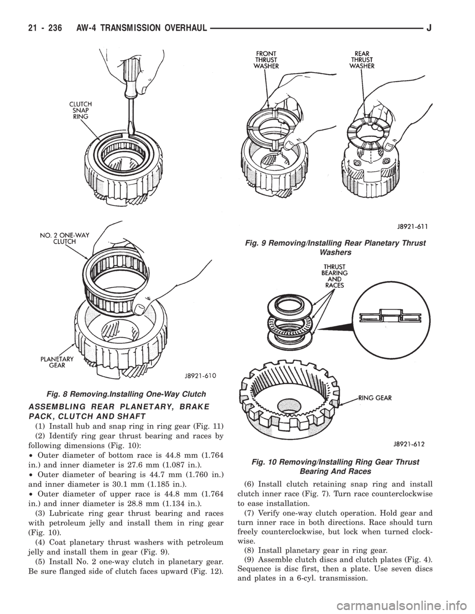
ASSEMBLING REAR PLANETARY, BRAKE
PACK, CLUTCH AND SHAFT
(1) Install hub and snap ring in ring gear (Fig. 11)
(2) Identify ring gear thrust bearing and races by
following dimensions (Fig. 10):
²Outer diameter of bottom race is 44.8 mm (1.764
in.) and inner diameter is 27.6 mm (1.087 in.).
²Outer diameter of bearing is 44.7 mm (1.760 in.)
and inner diameter is 30.1 mm (1.185 in.).
²Outer diameter of upper race is 44.8 mm (1.764
in.) and inner diameter is 28.8 mm (1.134 in.).
(3) Lubricate ring gear thrust bearing and races
with petroleum jelly and install them in ring gear
(Fig. 10).
(4) Coat planetary thrust washers with petroleum
jelly and install them in gear (Fig. 9).
(5) Install No. 2 one-way clutch in planetary gear.
Be sure flanged side of clutch faces upward (Fig. 12).(6) Install clutch retaining snap ring and install
clutch inner race (Fig. 7). Turn race counterclockwise
to ease installation.
(7) Verify one-way clutch operation. Hold gear and
turn inner race in both directions. Race should turn
freely counterclockwise, but lock when turned clock-
wise.
(8) Install planetary gear in ring gear.
(9) Assemble clutch discs and clutch plates (Fig. 4).
Sequence is disc first, then a plate. Use seven discs
and plates in a 6-cyl. transmission.
Fig. 8 Removing.Installing One-Way Clutch
Fig. 9 Removing/Installing Rear Planetary Thrust
Washers
Fig. 10 Removing/Installing Ring Gear Thrust
Bearing And Races
21 - 236 AW-4 TRANSMISSION OVERHAULJ
Page 1348 of 1784
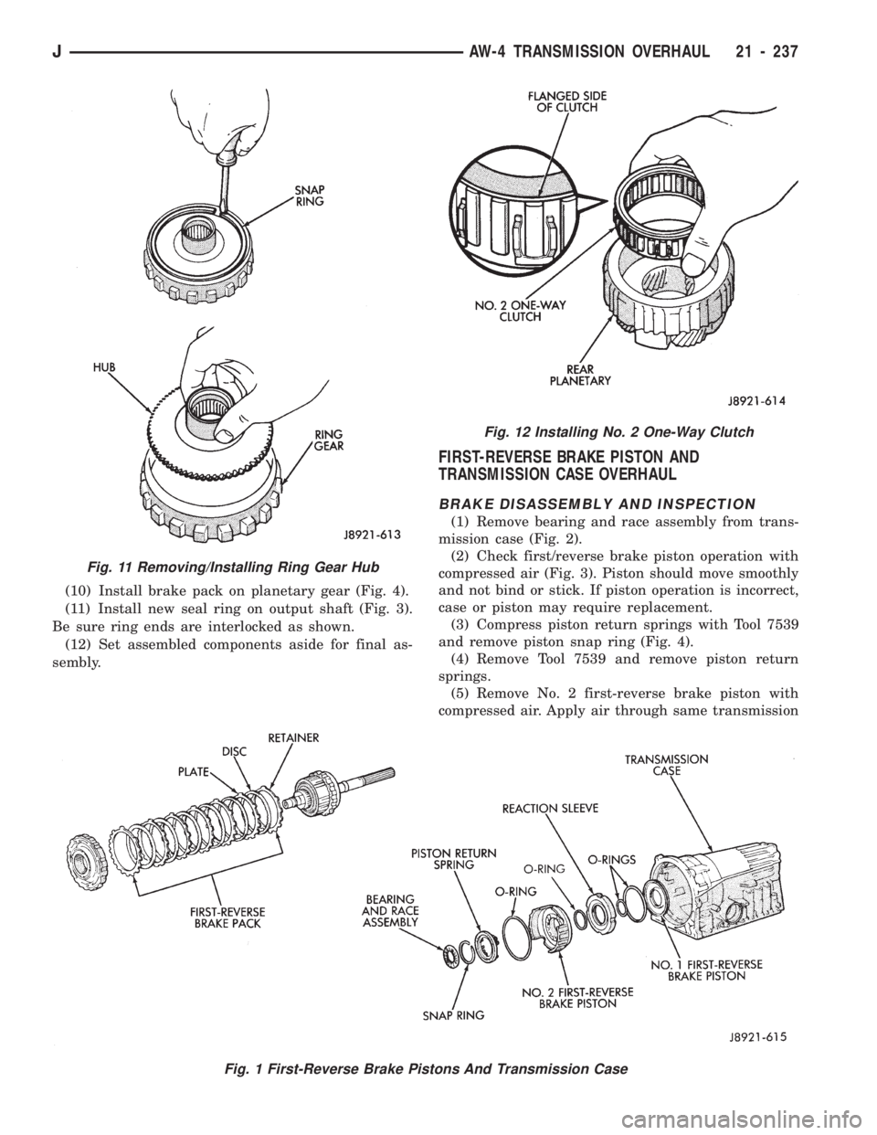
(10) Install brake pack on planetary gear (Fig. 4).
(11) Install new seal ring on output shaft (Fig. 3).
Be sure ring ends are interlocked as shown.
(12) Set assembled components aside for final as-
sembly.
FIRST-REVERSE BRAKE PISTON AND
TRANSMISSION CASE OVERHAUL
BRAKE DISASSEMBLY AND INSPECTION
(1) Remove bearing and race assembly from trans-
mission case (Fig. 2).
(2) Check first/reverse brake piston operation with
compressed air (Fig. 3). Piston should move smoothly
and not bind or stick. If piston operation is incorrect,
case or piston may require replacement.
(3) Compress piston return springs with Tool 7539
and remove piston snap ring (Fig. 4).
(4) Remove Tool 7539 and remove piston return
springs.
(5) Remove No. 2 first-reverse brake piston with
compressed air. Apply air through same transmission
Fig. 1 First-Reverse Brake Pistons And Transmission Case
Fig. 11 Removing/Installing Ring Gear Hub
Fig. 12 Installing No. 2 One-Way Clutch
JAW-4 TRANSMISSION OVERHAUL 21 - 237
Page 1358 of 1784
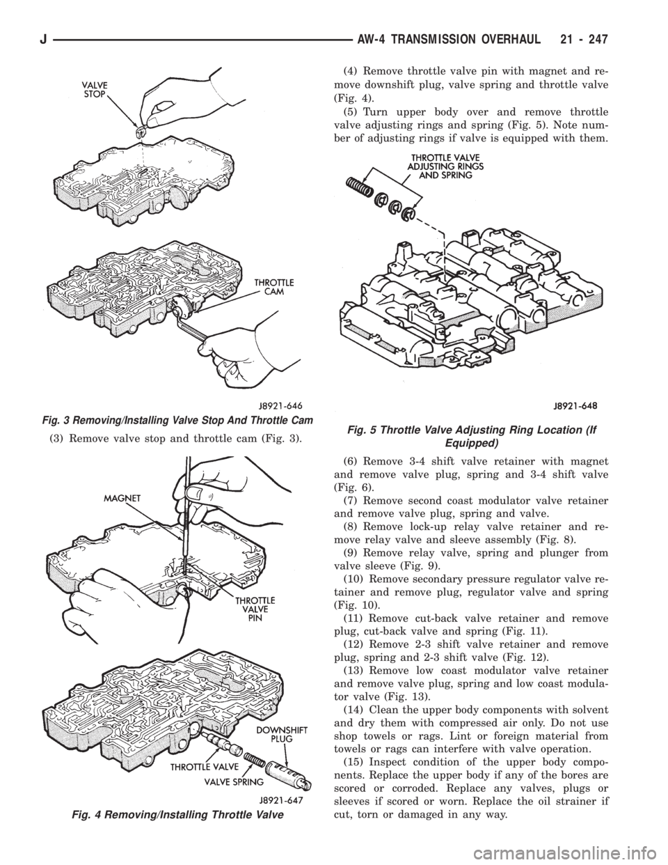
(3) Remove valve stop and throttle cam (Fig. 3).(4) Remove throttle valve pin with magnet and re-
move downshift plug, valve spring and throttle valve
(Fig. 4).
(5) Turn upper body over and remove throttle
valve adjusting rings and spring (Fig. 5). Note num-
ber of adjusting rings if valve is equipped with them.
(6) Remove 3-4 shift valve retainer with magnet
and remove valve plug, spring and 3-4 shift valve
(Fig. 6).
(7) Remove second coast modulator valve retainer
and remove valve plug, spring and valve.
(8) Remove lock-up relay valve retainer and re-
move relay valve and sleeve assembly (Fig. 8).
(9) Remove relay valve, spring and plunger from
valve sleeve (Fig. 9).
(10) Remove secondary pressure regulator valve re-
tainer and remove plug, regulator valve and spring
(Fig. 10).
(11) Remove cut-back valve retainer and remove
plug, cut-back valve and spring (Fig. 11).
(12) Remove 2-3 shift valve retainer and remove
plug, spring and 2-3 shift valve (Fig. 12).
(13) Remove low coast modulator valve retainer
and remove valve plug, spring and low coast modula-
tor valve (Fig. 13).
(14) Clean the upper body components with solvent
and dry them with compressed air only. Do not use
shop towels or rags. Lint or foreign material from
towels or rags can interfere with valve operation.
(15) Inspect condition of the upper body compo-
nents. Replace the upper body if any of the bores are
scored or corroded. Replace any valves, plugs or
sleeves if scored or worn. Replace the oil strainer if
cut, torn or damaged in any way.
Fig. 3 Removing/Installing Valve Stop And Throttle Cam
Fig. 4 Removing/Installing Throttle Valve
Fig. 5 Throttle Valve Adjusting Ring Location (If
Equipped)
JAW-4 TRANSMISSION OVERHAUL 21 - 247
Page 1361 of 1784
(16) Inspect the valve body springs. Replace any
spring having rusted, distorted, or collapsed coils.
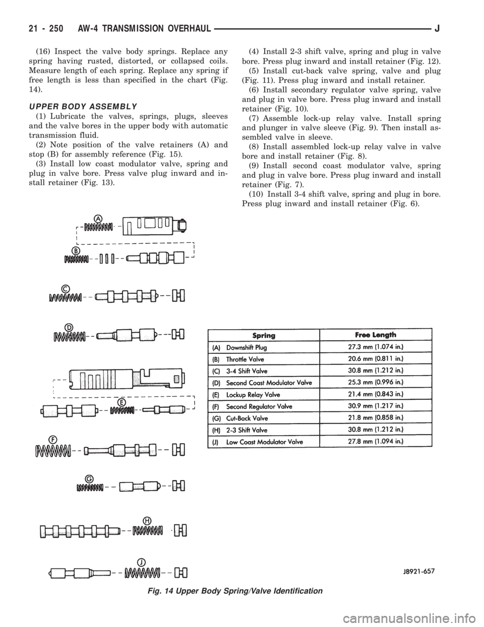
Measure length of each spring. Replace any spring if
free length is less than specified in the chart (Fig.
14).
UPPER BODY ASSEMBLY
(1) Lubricate the valves, springs, plugs, sleeves
and the valve bores in the upper body with automatic
transmission fluid.
(2) Note position of the valve retainers (A) and
stop (B) for assembly reference (Fig. 15).
(3) Install low coast modulator valve, spring and
plug in valve bore. Press valve plug inward and in-
stall retainer (Fig. 13).(4) Install 2-3 shift valve, spring and plug in valve
bore. Press plug inward and install retainer (Fig. 12).
(5) Install cut-back valve spring, valve and plug
(Fig. 11). Press plug inward and install retainer.
(6) Install secondary regulator valve spring, valve
and plug in valve bore. Press plug inward and install
retainer (Fig. 10).
(7) Assemble lock-up relay valve. Install spring
and plunger in valve sleeve (Fig. 9). Then install as-
sembled valve in sleeve.
(8) Install assembled lock-up relay valve in valve
bore and install retainer (Fig. 8).
(9) Install second coast modulator valve, spring
and plug in valve bore. Press plug inward and install
retainer (Fig. 7).
(10) Install 3-4 shift valve, spring and plug in bore.
Press plug inward and install retainer (Fig. 6).
Fig. 14 Upper Body Spring/Valve Identification
21 - 250 AW-4 TRANSMISSION OVERHAULJ
Page 1368 of 1784
(12) Install second brake drum gasket with Installer
Tool 7544 (Fig. 9). Gasket depth is 43.7 mm (1.720 in.).
(13) Install park lock pawl, spring and pin (Fig.
10).
(14) Connect park lock rod to manual valve shift
sector (Fig. 11).
(15) Position park lock rod bracket on case and
tighten bracket attaching bolts to 10 Nzm (7 ft. lbs.)
torque (Fig. 12).
(16) Verify park lock operation. Move shift sector
to Park position. Park pawl should be firmly engaged
(locked) in planetary ring gear (Fig. 13).
Fig. 7 Checking First-Reverse Brake Pack Clearance
Fig. 8 Installing Second Brake piston Sleeve
Fig. 9 Installing Second Brake Drum Gasket
Fig. 10 Installing Park Lock Pin, Spring And Pawl
Fig. 11 Installing Park Lock Rod
JAW-4 TRANSMISSION OVERHAUL 21 - 257
Page 1370 of 1784
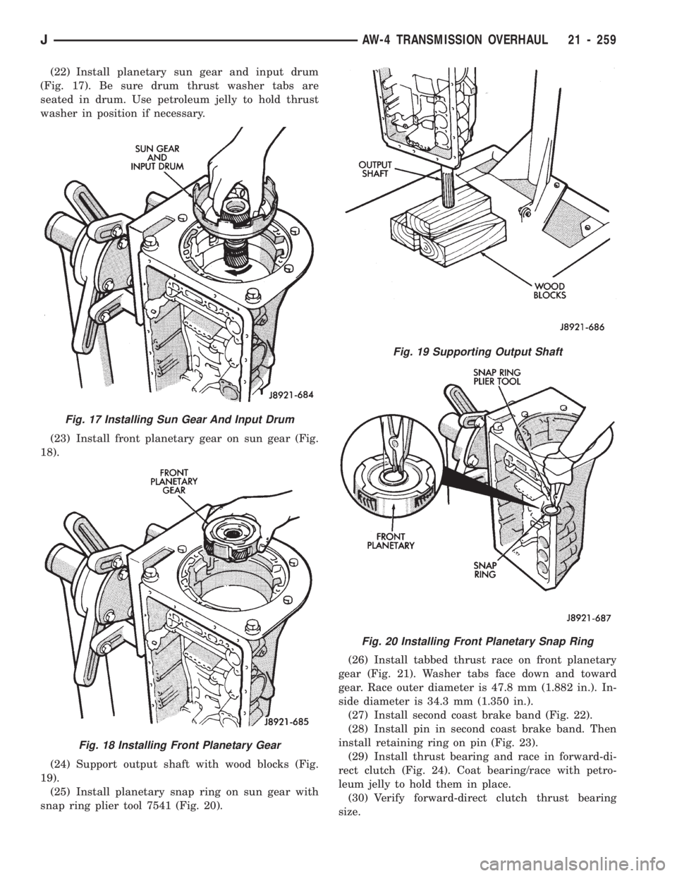
(22) Install planetary sun gear and input drum
(Fig. 17). Be sure drum thrust washer tabs are
seated in drum. Use petroleum jelly to hold thrust
washer in position if necessary.
(23) Install front planetary gear on sun gear (Fig.
18).
(24) Support output shaft with wood blocks (Fig.
19).
(25) Install planetary snap ring on sun gear with
snap ring plier tool 7541 (Fig. 20).(26) Install tabbed thrust race on front planetary
gear (Fig. 21). Washer tabs face down and toward
gear. Race outer diameter is 47.8 mm (1.882 in.). In-
side diameter is 34.3 mm (1.350 in.).
(27) Install second coast brake band (Fig. 22).
(28) Install pin in second coast brake band. Then
install retaining ring on pin (Fig. 23).
(29) Install thrust bearing and race in forward-di-
rect clutch (Fig. 24). Coat bearing/race with petro-
leum jelly to hold them in place.
(30) Verify forward-direct clutch thrust bearing
size.
Fig. 17 Installing Sun Gear And Input Drum
Fig. 18 Installing Front Planetary Gear
Fig. 19 Supporting Output Shaft
Fig. 20 Installing Front Planetary Snap Ring
JAW-4 TRANSMISSION OVERHAUL 21 - 259
Page 1378 of 1784
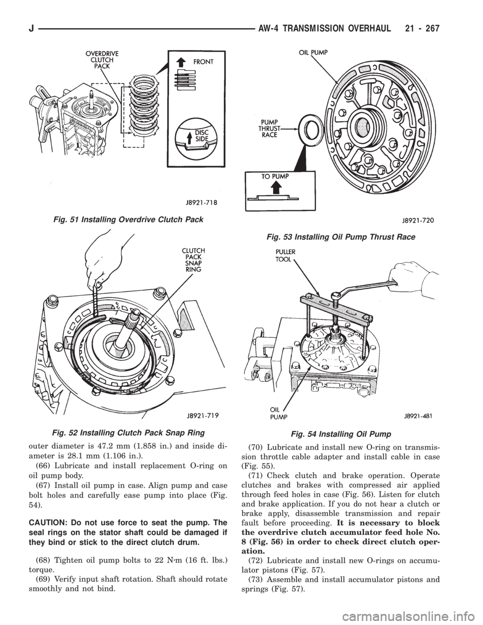
outer diameter is 47.2 mm (1.858 in.) and inside di-
ameter is 28.1 mm (1.106 in.).
(66) Lubricate and install replacement O-ring on
oil pump body.
(67) Install oil pump in case. Align pump and case
bolt holes and carefully ease pump into place (Fig.
54).
CAUTION: Do not use force to seat the pump. The
seal rings on the stator shaft could be damaged if
they bind or stick to the direct clutch drum.
(68) Tighten oil pump bolts to 22 Nzm (16 ft. lbs.)
torque.
(69) Verify input shaft rotation. Shaft should rotate
smoothly and not bind.(70) Lubricate and install new O-ring on transmis-
sion throttle cable adapter and install cable in case
(Fig. 55).
(71) Check clutch and brake operation. Operate
clutches and brakes with compressed air applied
through feed holes in case (Fig. 56). Listen for clutch
and brake application. If you do not hear a clutch or
brake apply, disassemble transmission and repair
fault before proceeding.It is necessary to block
the overdrive clutch accumulator feed hole No.
8 (Fig. 56) in order to check direct clutch oper-
ation.
(72) Lubricate and install new O-rings on accumu-
lator pistons (Fig. 57).
(73) Assemble and install accumulator pistons and
springs (Fig. 57).
Fig. 53 Installing Oil Pump Thrust Race
Fig. 54 Installing Oil Pump
Fig. 51 Installing Overdrive Clutch Pack
Fig. 52 Installing Clutch Pack Snap Ring
JAW-4 TRANSMISSION OVERHAUL 21 - 267