1994 JEEP CHEROKEE lock
[x] Cancel search: lockPage 1655 of 1784
BODY COMPONENTSÐREFINISHING
CONTENTS
page page
PAINT APPLICATION................... 201SERVICE INFORMATION................ 200
SERVICE INFORMATION
SAFETY PRECAUTIONS
Protective eye shields, masks, respirators, should
be used.
For maximum protection from paint solvent vapor,
use a fresh-air type, compressor-powered respirator.
PREPARATION
Do not allow any type of open flame or other source
of vapor ignition in the painting area. Paint vapor is
highly flammable when it is concentrated.
²Paint only in a well ventilated area.
²Use a good quality, high capacity respirator.
²Use protective goggles and clothing.
²Use rubber or latex gloves when mixing paint and
other, similar liquid products.
²When not in use, keep paint containers in a pro-
tective cabinet or locker.
²Keep the paint storage area well ventilated.
TECHNICAL TERMS
SINGLE COAT
A single-coat spray pattern is applied from left-to-
right. Then, the returning right-to-left spray pattern is
applied so that it overlaps the lower one-half of the ini-
tial spray pattern. This process is repeated until a com-
plete, single-coat coverage of a body panel is obtained.
DOUBLE COAT
A double-coat spray pattern is applied from left-to-
right. Then, the returning right-to-left spray pattern
is applied.
DRYING
Drying and hardening of paint film involves three
stages of evaporation.
The first stage is referred to as dust-free stage.
The second stage is referred to as tack-free stage.
The third and final stage is referred to as hard-dry0
stage.
DE-GREASE/DE-WAX
De-greasing/de-waxing involves cleaning a panel sur-
face with either 3M All purpose cleaner, or a similar
product. This removes the surface grease, or wax.
FEATHEREDGING
Tapering and blending the edges of repaired areas
is referred to as featheredging.
FERROUS AND NON-FERROUS METAL
Iron and steel are ferrous metals. Non-ferrous
metal includes aluminum, brass, copper, magnesium
and several types of alloy metal.
FLASH TIME
The time required for most of the solvent to evap-
orate from an applied primer/paint coat.
MIST COAT
A mist coat is frequently used as the final color
coat. Mist coats are over-thinned paint that is
sprayed wet.
SURFACE PRIMER COAT
A surface primer coat must be applied over re-
paired as well as bare metal substrate. The primer
provides a bond between the metal and the color
(base) coat. Various types of surface primers and
primer/sealants are available. Surface primers are
available in either sandable or non-sandable form.
Glazing or spot putty can be applied to primer cov-
ered surfaces. The putty is used to fill the small im-
perfections that a standard primer will not to cover.
REDUCERS/THINNERS
Enamel reducers and lacquer thinners are mix-
tures of volatile liquids and are used to reduce sur-
face primers and color-coat paints. Use only the type
of reducer/thinner that is specified by the paint man-
ufacturer.Do not intermix different types of re-
ducer/thinner.
TACK RAG
Tack rags are used to wipe dust from a body panel
surface prior to primer/paint application. Dust parti-
cles will adhere to the tacky surface of the rag when
it is moved over a panel surface.
23 - 200 BODY COMPONENTSÐXJ VEHICLESJ
Page 1666 of 1784
MANIFOLD
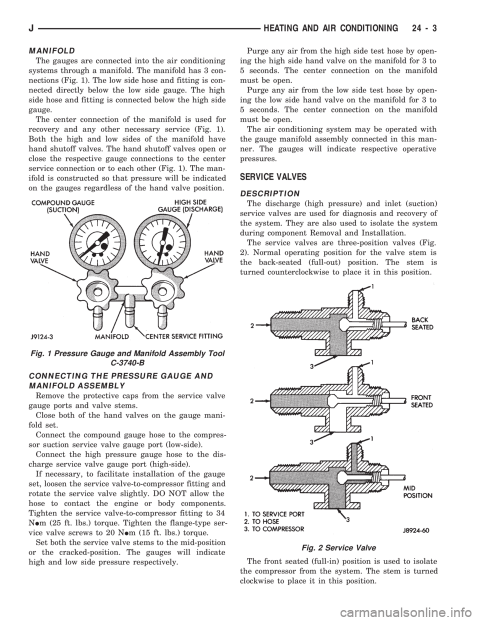
The gauges are connected into the air conditioning
systems through a manifold. The manifold has 3 con-
nections (Fig. 1). The low side hose and fitting is con-
nected directly below the low side gauge. The high
side hose and fitting is connected below the high side
gauge.
The center connection of the manifold is used for
recovery and any other necessary service (Fig. 1).
Both the high and low sides of the manifold have
hand shutoff valves. The hand shutoff valves open or
close the respective gauge connections to the center
service connection or to each other (Fig. 1). The man-
ifold is constructed so that pressure will be indicated
on the gauges regardless of the hand valve position.
CONNECTING THE PRESSURE GAUGE AND
MANIFOLD ASSEMBLY
Remove the protective caps from the service valve
gauge ports and valve stems.
Close both of the hand valves on the gauge mani-
fold set.
Connect the compound gauge hose to the compres-
sor suction service valve gauge port (low-side).
Connect the high pressure gauge hose to the dis-
charge service valve gauge port (high-side).
If necessary, to facilitate installation of the gauge
set, loosen the service valve-to-compressor fitting and
rotate the service valve slightly. DO NOT allow the
hose to contact the engine or body components.
Tighten the service valve-to-compressor fitting to 34
NIm (25 ft. lbs.) torque. Tighten the flange-type ser-
vice valve screws to 20 NIm (15 ft. lbs.) torque.
Set both the service valve stems to the mid-position
or the cracked-position. The gauges will indicate
high and low side pressure respectively.Purge any air from the high side test hose by open-
ing the high side hand valve on the manifold for 3 to
5 seconds. The center connection on the manifold
must be open.
Purge any air from the low side test hose by open-
ing the low side hand valve on the manifold for 3 to
5 seconds. The center connection on the manifold
must be open.
The air conditioning system may be operated with
the gauge manifold assembly connected in this man-
ner. The gauges will indicate respective operative
pressures.
SERVICE VALVES
DESCRIPTION
The discharge (high pressure) and inlet (suction)
service valves are used for diagnosis and recovery of
the system. They are also used to isolate the system
during component Removal and Installation.
The service valves are three-position valves (Fig.
2). Normal operating position for the valve stem is
the back-seated (full-out) position. The stem is
turned counterclockwise to place it in this position.
The front seated (full-in) position is used to isolate
the compressor from the system. The stem is turned
clockwise to place it in this position.
Fig. 1 Pressure Gauge and Manifold Assembly Tool
C-3740-B
Fig. 2 Service Valve
JHEATING AND AIR CONDITIONING 24 - 3
Page 1668 of 1784
(2) Close all the hand valves.
(3) Connect the red charging hose to the discharge
service valve.
(4) Connect the blue charging hose to the inlet
(suction) service valve.
(5) Discharge the system. Leave the suction and
discharge service valves in the mid-position.
CAUTION: The system must be completely dis-
charged into a recovery device before evacuating. If
the system is still charged, refrigerant can enter
and damage the vacuum pump.
(6) Connect the vacuum pump hose to the vacuum
pump inlet.
(7) Open the low and high pressure control valves
on the charging station.
(8) Start the vacuum pump. Open the vacuum con-
trol valve and note the vacuum reading.
(9) Test the system for leaks as follows:
²Close the manifold hand valves.
²Stop the vacuum pump and observe the vacuum
reading.
²If the system is leak-free, vacuum will hold steady
at the level indicated when the pump was stopped. If
vacuum remains steady for 3-5 minutes, resume and
continue evacuation for a minimum of 30 minutes.
²If the system has a leak, vacuum will fall off or
rapidly drop to a 0 reading. If a leak exists, partially
charge the system. Find and repair the leak and re-
sume evacuation.
(10) Continue evacuating the system for a mini-
mum of 30 minutes after attaining the lowest vac-
uum level.
(11) Fill the station charging cylinder while the
system is evacuating.
(12) Close the vacuum control valve and stop the
vacuum pump.
(13) Observe low pressure gauge to determine if a
system leak exists. If the system is leak-free, the sys-
tem is now ready for charging.
SYSTEM CHARGE
CHARGE CAPACITY
The recommended system charge is 1.1 kg (38 oz.)
of R-12 refrigerant for XJ vehicles and 0.9 kg (32 oz.)
for YJ vehicles.
Add an additional 28 grams (1 fluid oz.) of
compressor oil to the system when a hose, re-
ceiver-drier, condenser, expansion valve or
evaporator core is replaced.
PORTABLE SERVICE STATION
(1) Fill the station charging cylinder. Refrigerant
should be observed rising in the cylinder sight glass.
(2) Slightly open the valve at the top of the cylin-
der when pressure in the charging cylinder and re-frigerant supply tank are equal. This relieves head
pressure allowing refrigerant to continue filling the
cylinder.
(3) Observe the pressure gauge at the top of the
cylinder. Rotate the plastic cover on the cylinder un-
til the pressure heading column corresponds with the
gauge pressure in-line with the sight glass.
FOR EXAMPLE:ÐThe pressure gauge at the top
of the cylinder indicates 483 kPa (70 psi). Locate the
column with the pressure heading of 483 (70) and ro-
tate the cover so the 483 (70) column aligns with the
sight glass.
(4) When refrigerant reaches the correct level in
the sight glass, close the right hand valve at cylinder
base and on the refrigerant drum.
(5) Close the valve at the top of the charging cyl-
inder.
(6) Check for bubbles in the refrigerant using the
cylinder sight glass. If bubbles appear in the refrig-
erant, tilt the charging station rearward momen-
tarily.
(7) Connect the heating element cord to the power
pack receptacle and turn the heater switch ON.
(8) Allow the refrigerant to warm for about 10
minutes while the vacuum pump is operating.
WARNING: WEAR GOGGLES TO PROTECT THE
EYES.
(9) Discharge and evacuate the system.
(10) Close the low pressure valve on the charging
station.
(11) Fully open the left hand refrigerant control
valve at the base of the cylinder and the high pres-
sure valve on the charging station.
(12) Charge the system.
(13) Close the refrigerant control valve and the
high pressure valve on the charging station.
CAUTION: DO NOT permit the liquid level to drop
below 0 on the cylinder sight glass.
(14) Close the manifold gauges after completion of
the charging operation and check the high and low
side pressures.
(15) Check system operation.
CAUTION: DO NOT check system pressures until
the high and low pressure valves on the charging
station are closed. The low pressure gauge could
be damaged if the valves are open.
(16) Close all the valves on the charging station
and close the refrigerant drum valve when all the op-
erations are completed.
(17) Back-seat the service valves by turning them
fully counterclockwise. Install the quick seal caps on
the valves afterward.
JHEATING AND AIR CONDITIONING 24 - 5
Page 1671 of 1784
SERVICE DIAGNOSISÐMECHANICAL
GENERAL
The reason for a decrease in cooling or heating ef-
ficiency must be understood before attempting repair
or replacement of parts. Determined if the condition
is the air conditioner, the heating system, its compo-
nents or the in the air flow system.
The air conditioning system generally operates at
peak efficiency at normal highway speeds. However,
a slight reduction in A/C performance may be expe-
rienced in congested city driving conditions; espe-
cially when ambient temperatures are high.
When diagnosing a gradual decrease in A/C perfor-
mance, remember to check condition of the condenser
and radiator fins. Air flow blockage of either compo-
nent, caused by dirt, foreign material or insects, will
affect the air conditioning and engine cooling sys-
tems. Vehicles equipped with a protective screen, can
restrict air flow to the radiator and condenser.
During high outside operating temperatures, a
slight increase in engine coolant temperature will oc-
cur when the air conditioner is operating.
A/C PERFORMANCE TEST
The pressure developed on the high side and low
side of the compressor indicates whether the system
is operating properly.
WARNING: USE EXTREME CAUTION WHEN THE
ENGINE IS OPERATING. DO NOT STAND IN A DI-
RECT LINE WITH THE FAN. DO NOT PUT YOUR
HANDS NEAR THE PULLEYS, BELTS OR FAN. DO
NOT WEAR LOOSE CLOTHING.
WARNING: WEAR SAFETY GOGGLES WHEN SER-
VICING THE REFRIGERATION SYSTEM
(1) Attach an engine tachometer and refrigerant
Pressure Gauge and Manifold Assembly Tool
C-4740-A.
(2) Close both hand valves on the gauge and man-
ifold assembly.
(3) Set both service hand valve stems to the mid-
position.
(4) Engine should be warmed up with doors, win-
dows and hood closed.
(5) Operate air conditioning system with the en-
gine running at 1,000 RPM. Set the controls for max-
imum A/C, temperature control on full cool and
blower switch on high.
(6) Insert a thermometer into center discharge air
outlet and observe the air temperature. The temper-
ature should be approximately 7ÉC (45ÉF) at 27ÉC
(80ÉF) ambient temperature after 5 minutes of oper-
ation.(7) Observe the high and low side pressures. The
evaporator suction pressure should be 207-241 kPag
(30-35 psig). The compressor discharge pressure
should be 1103-1633 kPag (160-235 psig). It should
be noted that high ambient temperature and humid-
ity conditions will cause higher pressures and tem-
perature conditions. If the clutch cycles, take
readings before clutch disengages.
(8) If pressures are abnormal, refer to the Pressure
and Performance Diagnosis Charts.
The following charts have been developed for quick
reference. If the step by step method used is not com-
pletely understood, refer to the correct section of the
Service Manual for more detailed information.
COMPRESSOR VALVE PLATEÐLEAK TESTS
This test can be preformed with the compressor in-
stalled in the vehicle.
Discharge or Suction Valve BreakageÐWhen
compressor is operating at idle speed, compressor
makes a ``clacking'' sound. Preform the Pressure Bal-
ancing Test.
Head Gasket BreakageÐAt idle speed, discharge
pressure does not increase to normal condition and
suction pressure is high. Preform the Pressure Bal-
ancing Test.
Pressure Balancing Test:
(1) Connect manifold gauge set to suction and dis-
charge ports.
(2) Run compressor for 5 minutes at idle speed and
stop.
(3) Measure elapsed time that discharge pressure
is balanced to suction pressure. If less than 2 min-
utes, it is determined that discharge valve or head
gasket is broken.
REFRIGERANT LEAK TEST
External leaks in the system can be located using
an electronic detector.
The electronic leak detector is recommended be-
cause it is light, accurate and most important, does
not expose the user to toxic gas fumes. An electronic
leak detector will locate R-12 leaks as small as 15 ml
(0.5 fluid oz.) per year.
WARNING: DO NOT USE A HALIDE TORCH. THE
HALIDE TORCH REQUIRES AN OPEN FLAME FOR
LEAK DETECTION. WHEN R-12 IS EXPOSED TO AN
OPEN FLAME, IT TURNS INTO PHOSGENE GAS
WHICH IS POISONOUS.
(1) Calibrate the detector as outlined in the manu-
facturer's instructions.
(2) Remove the flexible detector probe from the
case.
(3) Turn the detector control switch ON.
24 - 8 HEATING AND AIR CONDITIONINGJ
Page 1680 of 1784
COMPRESSOR OVERHAUL
INDEX
page page
Compressor............................. 17
Compressor Isolation...................... 17
Description............................. 17Magnetic Clutch......................... 18
Purging Compressor of Air................. 17
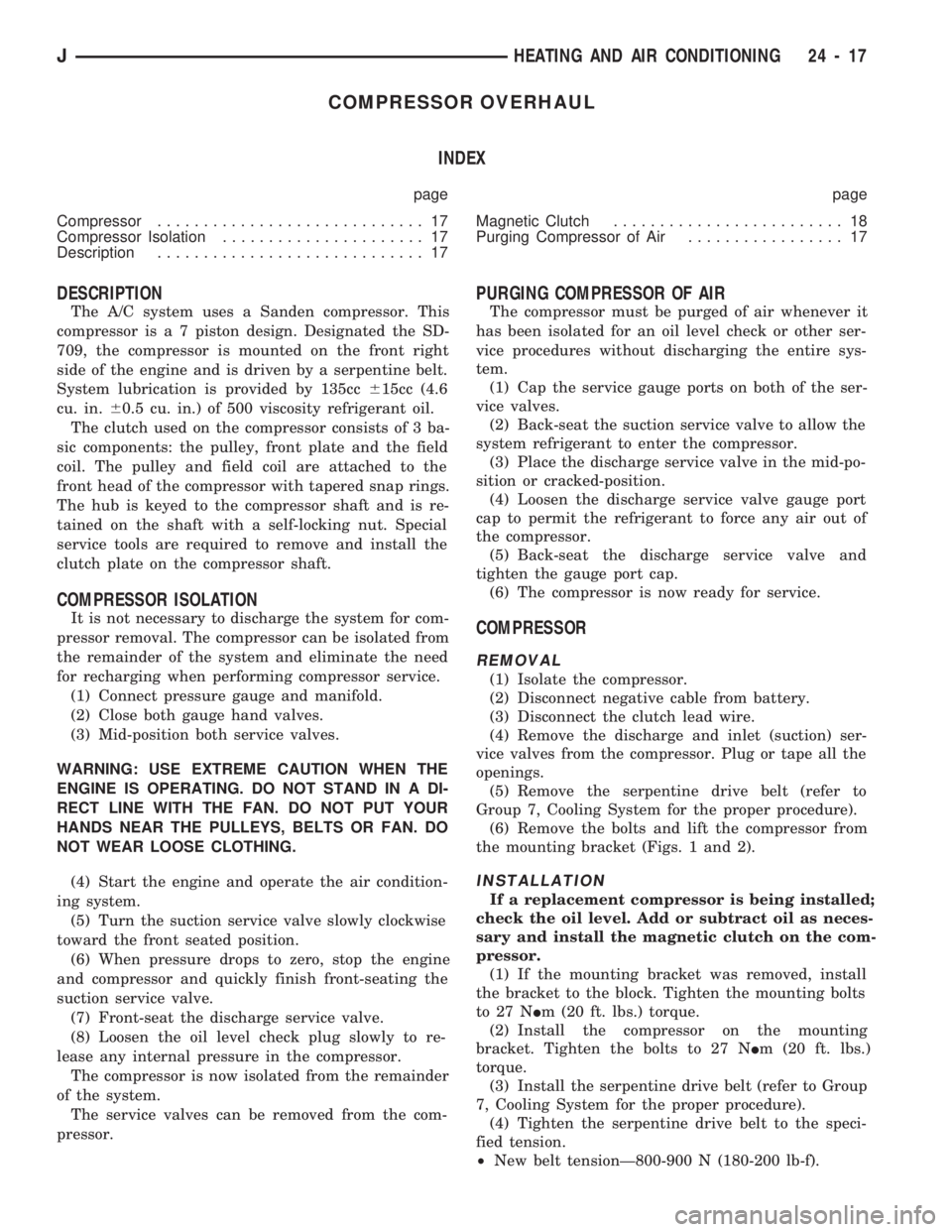
DESCRIPTION
The A/C system uses a Sanden compressor. This
compressor is a 7 piston design. Designated the SD-
709, the compressor is mounted on the front right
side of the engine and is driven by a serpentine belt.
System lubrication is provided by 135cc615cc (4.6
cu. in.60.5 cu. in.) of 500 viscosity refrigerant oil.
The clutch used on the compressor consists of 3 ba-
sic components: the pulley, front plate and the field
coil. The pulley and field coil are attached to the
front head of the compressor with tapered snap rings.
The hub is keyed to the compressor shaft and is re-
tained on the shaft with a self-locking nut. Special
service tools are required to remove and install the
clutch plate on the compressor shaft.
COMPRESSOR ISOLATION
It is not necessary to discharge the system for com-
pressor removal. The compressor can be isolated from
the remainder of the system and eliminate the need
for recharging when performing compressor service.
(1) Connect pressure gauge and manifold.
(2) Close both gauge hand valves.
(3) Mid-position both service valves.
WARNING: USE EXTREME CAUTION WHEN THE
ENGINE IS OPERATING. DO NOT STAND IN A DI-
RECT LINE WITH THE FAN. DO NOT PUT YOUR
HANDS NEAR THE PULLEYS, BELTS OR FAN. DO
NOT WEAR LOOSE CLOTHING.
(4) Start the engine and operate the air condition-
ing system.
(5) Turn the suction service valve slowly clockwise
toward the front seated position.
(6) When pressure drops to zero, stop the engine
and compressor and quickly finish front-seating the
suction service valve.
(7) Front-seat the discharge service valve.
(8) Loosen the oil level check plug slowly to re-
lease any internal pressure in the compressor.
The compressor is now isolated from the remainder
of the system.
The service valves can be removed from the com-
pressor.
PURGING COMPRESSOR OF AIR
The compressor must be purged of air whenever it
has been isolated for an oil level check or other ser-
vice procedures without discharging the entire sys-
tem.
(1) Cap the service gauge ports on both of the ser-
vice valves.
(2) Back-seat the suction service valve to allow the
system refrigerant to enter the compressor.
(3) Place the discharge service valve in the mid-po-
sition or cracked-position.
(4) Loosen the discharge service valve gauge port
cap to permit the refrigerant to force any air out of
the compressor.
(5) Back-seat the discharge service valve and
tighten the gauge port cap.
(6) The compressor is now ready for service.
COMPRESSOR
REMOVAL
(1) Isolate the compressor.
(2) Disconnect negative cable from battery.
(3) Disconnect the clutch lead wire.
(4) Remove the discharge and inlet (suction) ser-
vice valves from the compressor. Plug or tape all the
openings.
(5) Remove the serpentine drive belt (refer to
Group 7, Cooling System for the proper procedure).
(6) Remove the bolts and lift the compressor from
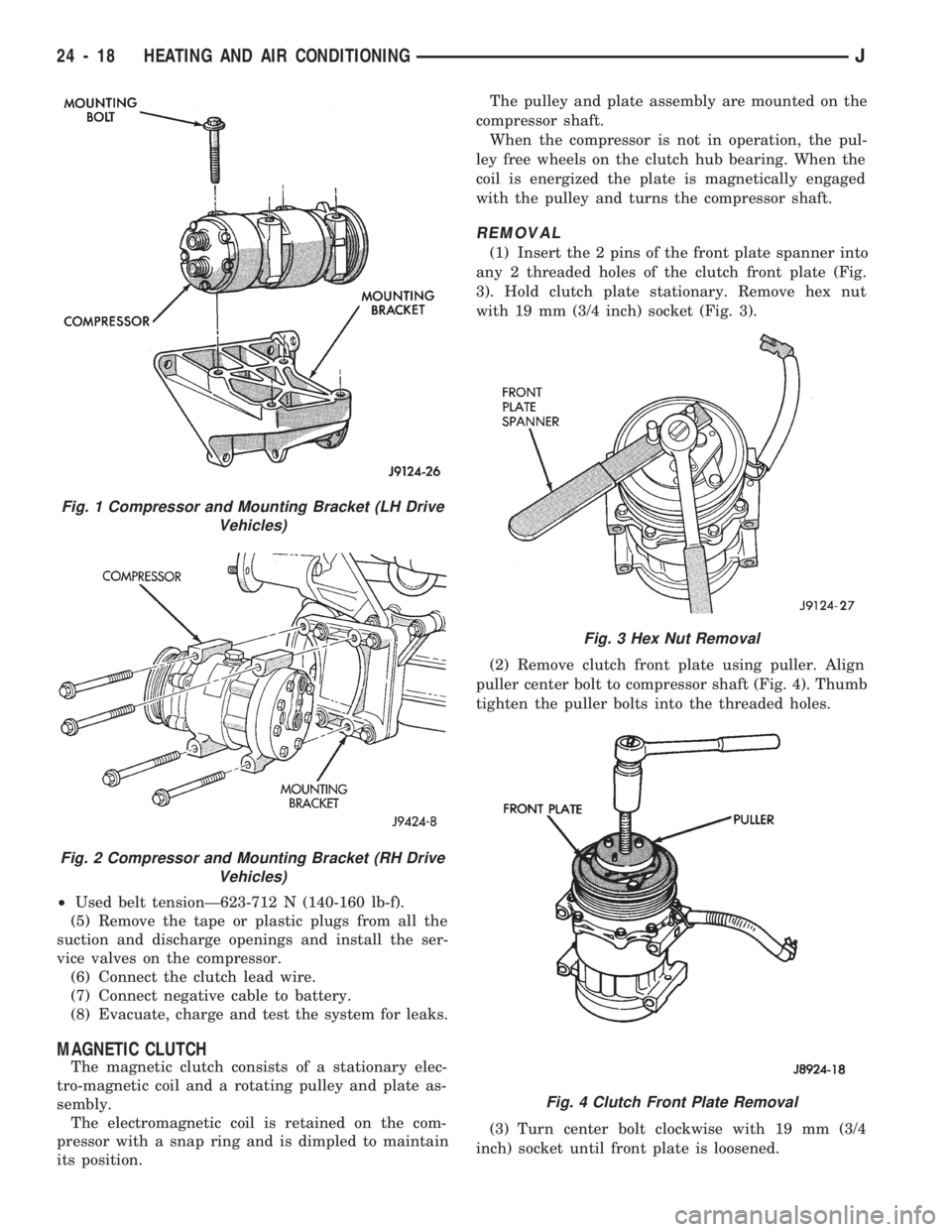
the mounting bracket (Figs. 1 and 2).
INSTALLATION
If a replacement compressor is being installed;
check the oil level. Add or subtract oil as neces-
sary and install the magnetic clutch on the com-
pressor.
(1) If the mounting bracket was removed, install
the bracket to the block. Tighten the mounting bolts
to 27 NIm (20 ft. lbs.) torque.
(2) Install the compressor on the mounting
bracket. Tighten the bolts to 27 NIm (20 ft. lbs.)
torque.
(3) Install the serpentine drive belt (refer to Group
7, Cooling System for the proper procedure).
(4) Tighten the serpentine drive belt to the speci-
fied tension.
²New belt tensionÐ800-900 N (180-200 lb-f).
JHEATING AND AIR CONDITIONING 24 - 17
Page 1681 of 1784
²Used belt tensionÐ623-712 N (140-160 lb-f).
(5) Remove the tape or plastic plugs from all the
suction and discharge openings and install the ser-
vice valves on the compressor.
(6) Connect the clutch lead wire.
(7) Connect negative cable to battery.
(8) Evacuate, charge and test the system for leaks.
MAGNETIC CLUTCH
The magnetic clutch consists of a stationary elec-
tro-magnetic coil and a rotating pulley and plate as-
sembly.
The electromagnetic coil is retained on the com-
pressor with a snap ring and is dimpled to maintain
its position.The pulley and plate assembly are mounted on the
compressor shaft.
When the compressor is not in operation, the pul-
ley free wheels on the clutch hub bearing. When the
coil is energized the plate is magnetically engaged
with the pulley and turns the compressor shaft.
REMOVAL
(1) Insert the 2 pins of the front plate spanner into
any 2 threaded holes of the clutch front plate (Fig.
3). Hold clutch plate stationary. Remove hex nut
with 19 mm (3/4 inch) socket (Fig. 3).
(2) Remove clutch front plate using puller. Align
puller center bolt to compressor shaft (Fig. 4). Thumb
tighten the puller bolts into the threaded holes.
(3) Turn center bolt clockwise with 19 mm (3/4
inch) socket until front plate is loosened.
Fig. 1 Compressor and Mounting Bracket (LH Drive
Vehicles)
Fig. 2 Compressor and Mounting Bracket (RH Drive
Vehicles)
Fig. 3 Hex Nut Removal
Fig. 4 Clutch Front Plate Removal
24 - 18 HEATING AND AIR CONDITIONINGJ
Page 1682 of 1784
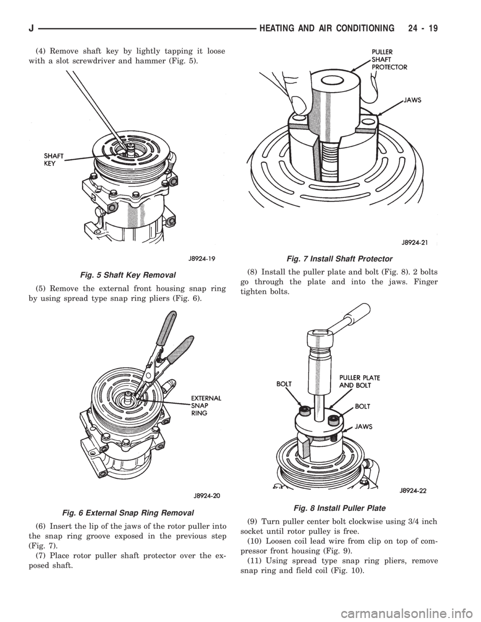
(4) Remove shaft key by lightly tapping it loose
with a slot screwdriver and hammer (Fig. 5).
(5) Remove the external front housing snap ring
by using spread type snap ring pliers (Fig. 6).
(6) Insert the lip of the jaws of the rotor puller into
the snap ring groove exposed in the previous step
(Fig. 7).
(7) Place rotor puller shaft protector over the ex-
posed shaft.(8) Install the puller plate and bolt (Fig. 8). 2 bolts
go through the plate and into the jaws. Finger
tighten bolts.
(9) Turn puller center bolt clockwise using 3/4 inch
socket until rotor pulley is free.
(10) Loosen coil lead wire from clip on top of com-
pressor front housing (Fig. 9).
(11) Using spread type snap ring pliers, remove
snap ring and field coil (Fig. 10).
Fig. 5 Shaft Key Removal
Fig. 6 External Snap Ring Removal
Fig. 7 Install Shaft Protector
Fig. 8 Install Puller Plate
JHEATING AND AIR CONDITIONING 24 - 19
Page 1689 of 1784
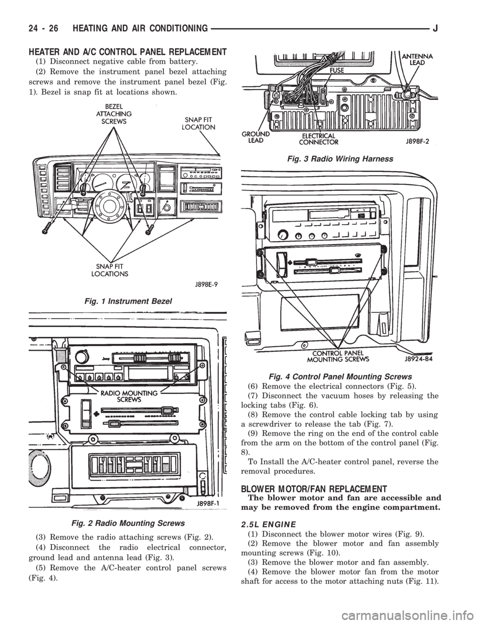
HEATER AND A/C CONTROL PANEL REPLACEMENT
(1) Disconnect negative cable from battery.
(2) Remove the instrument panel bezel attaching
screws and remove the instrument panel bezel (Fig.
1). Bezel is snap fit at locations shown.
(3) Remove the radio attaching screws (Fig. 2).
(4) Disconnect the radio electrical connector,
ground lead and antenna lead (Fig. 3).
(5) Remove the A/C-heater control panel screws
(Fig. 4).(6) Remove the electrical connectors (Fig. 5).
(7) Disconnect the vacuum hoses by releasing the
locking tabs (Fig. 6).
(8) Remove the control cable locking tab by using
a screwdriver to release the tab (Fig. 7).
(9) Remove the ring on the end of the control cable
from the arm on the bottom of the control panel (Fig.
8).
To Install the A/C-heater control panel, reverse the
removal procedures.
BLOWER MOTOR/FAN REPLACEMENT
The blower motor and fan are accessible and
may be removed from the engine compartment.
2.5L ENGINE
(1) Disconnect the blower motor wires (Fig. 9).
(2) Remove the blower motor and fan assembly
mounting screws (Fig. 10).
(3) Remove the blower motor and fan assembly.
(4) Remove the blower motor fan from the motor
shaft for access to the motor attaching nuts (Fig. 11).
Fig. 1 Instrument Bezel
Fig. 2 Radio Mounting Screws
Fig. 3 Radio Wiring Harness
Fig. 4 Control Panel Mounting Screws
24 - 26 HEATING AND AIR CONDITIONINGJ