1994 JEEP CHEROKEE lock
[x] Cancel search: lockPage 1169 of 1784
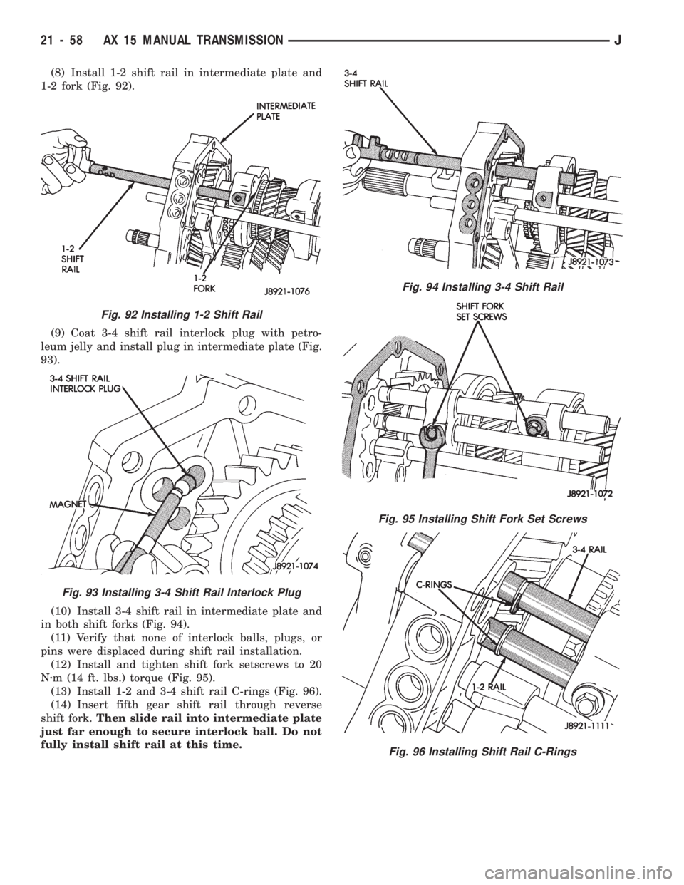
(8) Install 1-2 shift rail in intermediate plate and
1-2 fork (Fig. 92).
(9) Coat 3-4 shift rail interlock plug with petro-
leum jelly and install plug in intermediate plate (Fig.
93).
(10) Install 3-4 shift rail in intermediate plate and
in both shift forks (Fig. 94).
(11) Verify that none of interlock balls, plugs, or
pins were displaced during shift rail installation.
(12) Install and tighten shift fork setscrews to 20
Nzm (14 ft. lbs.) torque (Fig. 95).
(13) Install 1-2 and 3-4 shift rail C-rings (Fig. 96).
(14) Insert fifth gear shift rail through reverse
shift fork.Then slide rail into intermediate plate
just far enough to secure interlock ball. Do not
fully install shift rail at this time.
Fig. 94 Installing 3-4 Shift Rail
Fig. 95 Installing Shift Fork Set Screws
Fig. 96 Installing Shift Rail C-Rings
Fig. 92 Installing 1-2 Shift Rail
Fig. 93 Installing 3-4 Shift Rail Interlock Plug
21 - 58 AX 15 MANUAL TRANSMISSIONJ
Page 1170 of 1784
FIFTH-REVERSE GEAR AND SHIFT
COMPONENT INSTALLATION
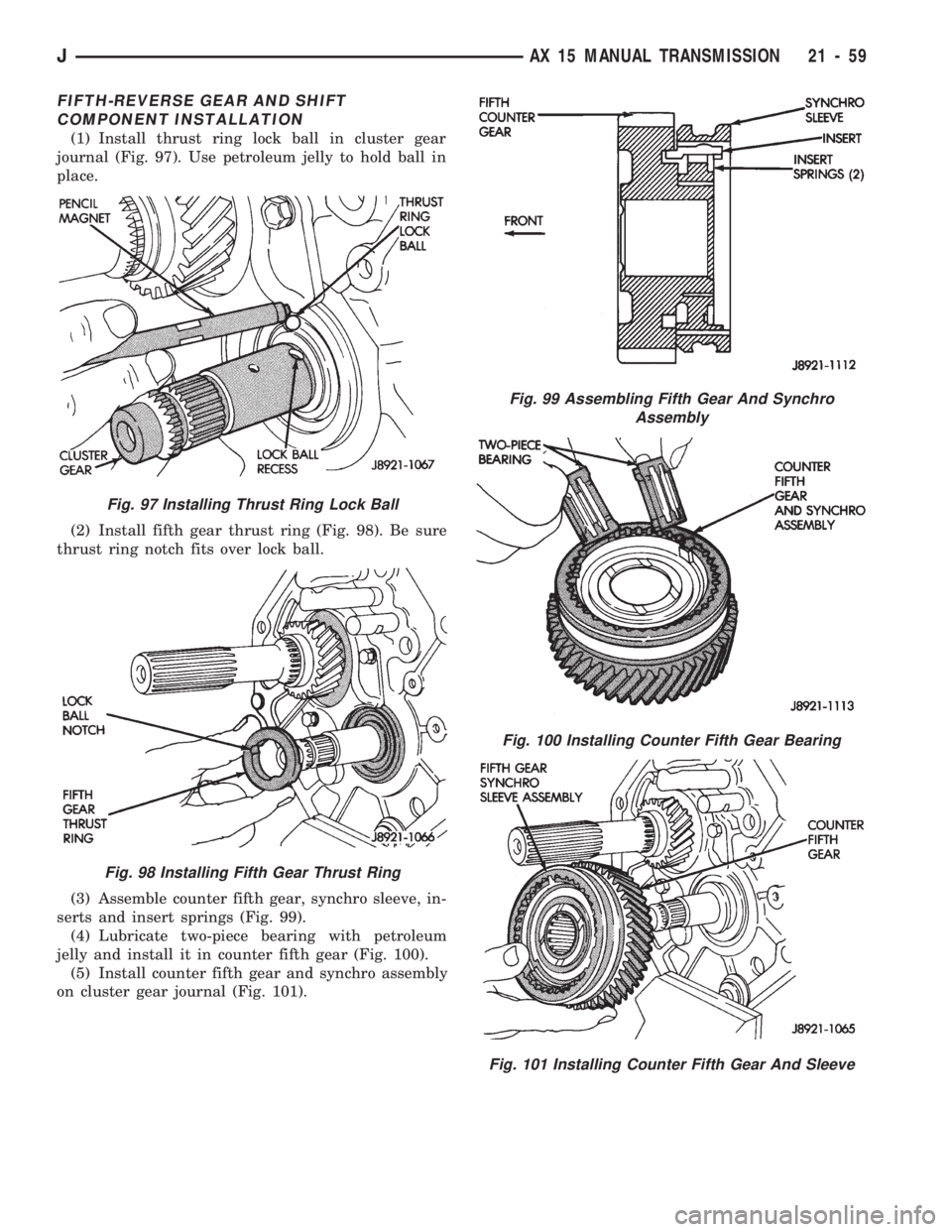
(1) Install thrust ring lock ball in cluster gear
journal (Fig. 97). Use petroleum jelly to hold ball in
place.
(2) Install fifth gear thrust ring (Fig. 98). Be sure
thrust ring notch fits over lock ball.
(3) Assemble counter fifth gear, synchro sleeve, in-
serts and insert springs (Fig. 99).
(4) Lubricate two-piece bearing with petroleum
jelly and install it in counter fifth gear (Fig. 100).
(5) Install counter fifth gear and synchro assembly
on cluster gear journal (Fig. 101).
Fig. 97 Installing Thrust Ring Lock Ball
Fig. 98 Installing Fifth Gear Thrust Ring
Fig. 99 Assembling Fifth Gear And Synchro
Assembly
Fig. 100 Installing Counter Fifth Gear Bearing
Fig. 101 Installing Counter Fifth Gear And Sleeve
JAX 15 MANUAL TRANSMISSION 21 - 59
Page 1171 of 1784
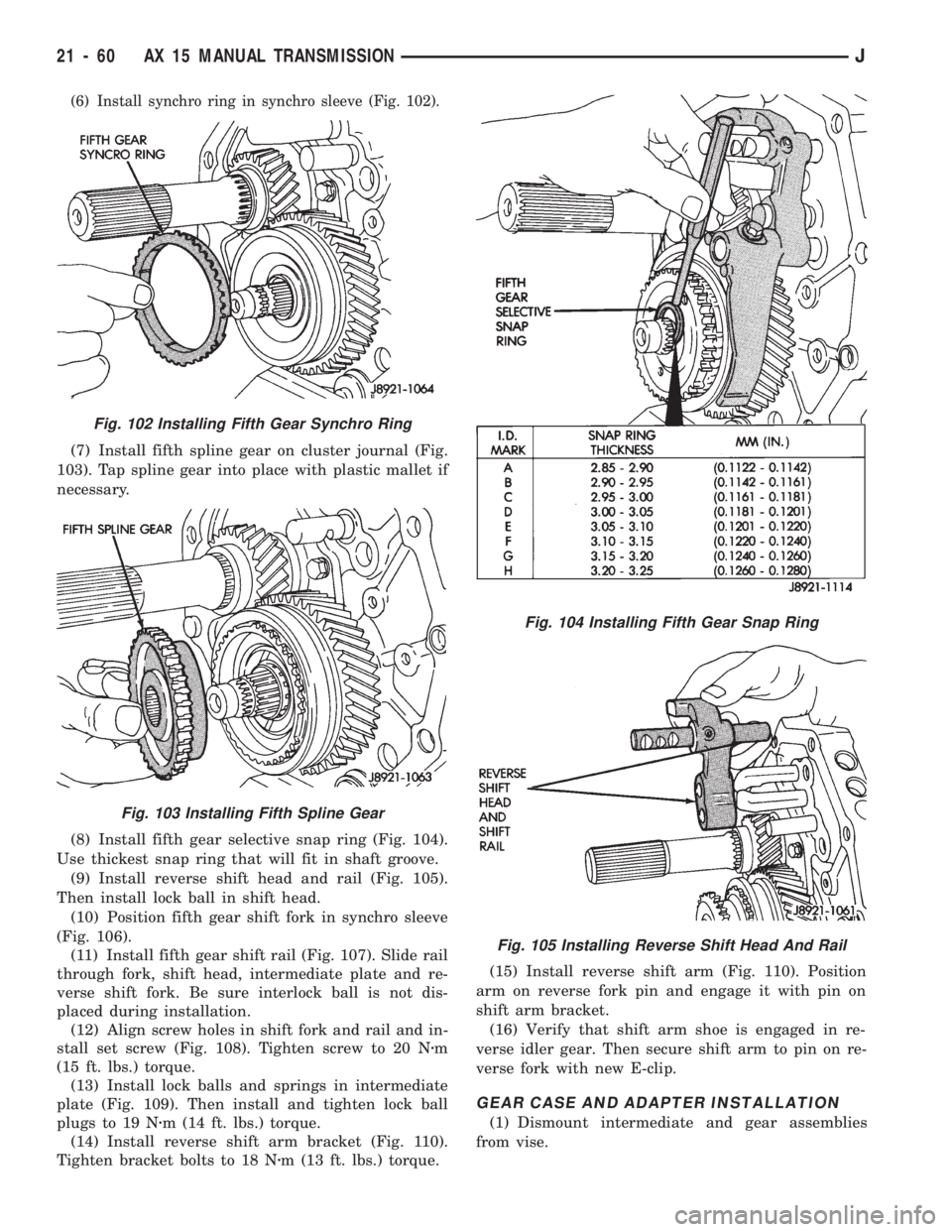
(6) Install synchro ring in synchro sleeve (Fig. 102).
(7) Install fifth spline gear on cluster journal (Fig.
103). Tap spline gear into place with plastic mallet if
necessary.
(8) Install fifth gear selective snap ring (Fig. 104).
Use thickest snap ring that will fit in shaft groove.
(9) Install reverse shift head and rail (Fig. 105).
Then install lock ball in shift head.
(10) Position fifth gear shift fork in synchro sleeve
(Fig. 106).
(11) Install fifth gear shift rail (Fig. 107). Slide rail
through fork, shift head, intermediate plate and re-
verse shift fork. Be sure interlock ball is not dis-
placed during installation.
(12) Align screw holes in shift fork and rail and in-
stall set screw (Fig. 108). Tighten screw to 20 Nzm
(15 ft. lbs.) torque.
(13) Install lock balls and springs in intermediate
plate (Fig. 109). Then install and tighten lock ball
plugs to 19 Nzm (14 ft. lbs.) torque.
(14) Install reverse shift arm bracket (Fig. 110).
Tighten bracket bolts to 18 Nzm (13 ft. lbs.) torque.(15) Install reverse shift arm (Fig. 110). Position
arm on reverse fork pin and engage it with pin on
shift arm bracket.
(16) Verify that shift arm shoe is engaged in re-
verse idler gear. Then secure shift arm to pin on re-
verse fork with new E-clip.
GEAR CASE AND ADAPTER INSTALLATION
(1) Dismount intermediate and gear assemblies
from vise.
Fig. 104 Installing Fifth Gear Snap Ring
Fig. 105 Installing Reverse Shift Head And Rail
Fig. 102 Installing Fifth Gear Synchro Ring
Fig. 103 Installing Fifth Spline Gear
21 - 60 AX 15 MANUAL TRANSMISSIONJ
Page 1173 of 1784
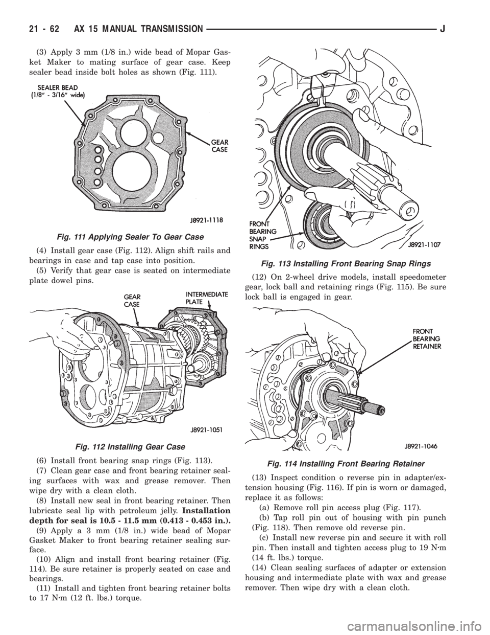
(3) Apply 3 mm (1/8 in.) wide bead of Mopar Gas-
ket Maker to mating surface of gear case. Keep
sealer bead inside bolt holes as shown (Fig. 111).
(4) Install gear case (Fig. 112). Align shift rails and
bearings in case and tap case into position.
(5) Verify that gear case is seated on intermediate
plate dowel pins.
(6) Install front bearing snap rings (Fig. 113).
(7) Clean gear case and front bearing retainer seal-
ing surfaces with wax and grease remover. Then
wipe dry with a clean cloth.
(8) Install new seal in front bearing retainer. Then
lubricate seal lip with petroleum jelly.Installation
depth for seal is 10.5 - 11.5 mm (0.413 - 0.453 in.).
(9) Applya3mm(1/8 in.) wide bead of Mopar
Gasket Maker to front bearing retainer sealing sur-
face.
(10) Align and install front bearing retainer (Fig.
114). Be sure retainer is properly seated on case and
bearings.
(11) Install and tighten front bearing retainer bolts
to 17 Nzm (12 ft. lbs.) torque.(12) On 2-wheel drive models, install speedometer
gear, lock ball and retaining rings (Fig. 115). Be sure
lock ball is engaged in gear.
(13) Inspect condition o reverse pin in adapter/ex-
tension housing (Fig. 116). If pin is worn or damaged,
replace it as follows:
(a) Remove roll pin access plug (Fig. 117).
(b) Tap roll pin out of housing with pin punch
(Fig. 118). Then remove old reverse pin.
(c) Install new reverse pin and secure it with roll
pin. Then install and tighten access plug to 19 Nzm
(14 ft. lbs.) torque.
(14) Clean sealing surfaces of adapter or extension
housing and intermediate plate with wax and grease
remover. Then wipe dry with a clean cloth.
Fig. 111 Applying Sealer To Gear Case
Fig. 112 Installing Gear Case
Fig. 113 Installing Front Bearing Snap Rings
Fig. 114 Installing Front Bearing Retainer
21 - 62 AX 15 MANUAL TRANSMISSIONJ
Page 1179 of 1784
controlled by throttle pressure, which is dependent
on the degree of throttle opening.
The governor valve is operated by the transmission
output shaft. Governor pressure increases in propor-
tion to vehicle speed.
The throttle valve determines line pressure and
shift speed. The throttle valve also controls upshift
and downshift speeds by regulating pressure in con-
junction with throttle position.
Shift Valves
The manual valve is operated by the gearshift link-
age and provides the operating range selected by the
driver.
The 1-2 shift valve provides automatic 1-2 or 2-1
shifts and the 2-3 shift valve provides automatic 2-3
or 3-2 shifts. The kickdown valve provides forced 3-2
or 3-1 downshifts depending on vehicle speed. Down-
shifts occur when the throttle is opened beyond
downshift detent position which is just before wide
open throttle.
The 2-3 valve throttle pressure plug provides 3-2
downshifts with varying throttle openings and de-
pending on vehicle speed. The 1-2 shift control valve
transmits 1-2 shift pressure to the accumulator pis-
ton to control kickdown band capacity on 1-2 upshifts
and 3-2 downshifts.The shuttle valve has two functions. First is fast
front band release and smooth engagement during
lift-foot 2-3 upshifts. The second is to regulate front
clutch and band application during 3-2 downshifts.
Clutches-Bands-Servos-Accumulator
The front/rear clutch pistons and servo pistons are
actuated by line pressure. When line pressure is re-
moved, the pistons are released by spring tension.
On 2-3 upshifts, the front servo piston is released
by spring tension and hydraulic pressure. The accu-
mulator controls hydraulic pressure on the apply side
of the front servo during 1-2 upshifts and at all
throttle openings.
Converter Clutch Controls
Converter clutch operation is controlled by the
power train control module, and by the solenoid and
clutch module on the valve body. The solenoid is op-
erated by a relay on the engine compartment side of
the dash panel.
Activating the solenoid opens a vent allowing fluid
to flow into the clutch module. When line pressure
exceeds tension of the module valve springs, the
module valves open. This allows fluid to be chan-
neled to the converter clutch through the reaction
shaft support and transmission shaft.
Gearshift And Parking Lock Controls
The gearshift lever provides six operating posi-
tions: Park (P), Reverse (R), Neutral (N), and the D,
2 and 1 forward drive ranges.
Manual 1 position provides first gear only. Overrun
braking occurs in 1 range when the throttle is re-
leased. Upshifts are not provided in 1 range.
Manual 2 range provides first and second gear. A
1-2 upshift will take place but a 2-3 upshift will not
occur.
D position provides 1-2, 2-3 upshifts and 3-2 and
3-1 downshifts.
Park position allows the park rod to move the park
pawl into engagement with the park gear. This pre-
vents rotation of the transmission output shaft. The
park lock mechanism is only engaged when the shift
lever is in the Park detent.
A park/neutral position switch controls engine
starting. The switch is designed to allow engine
starts only in park or neutral positions.
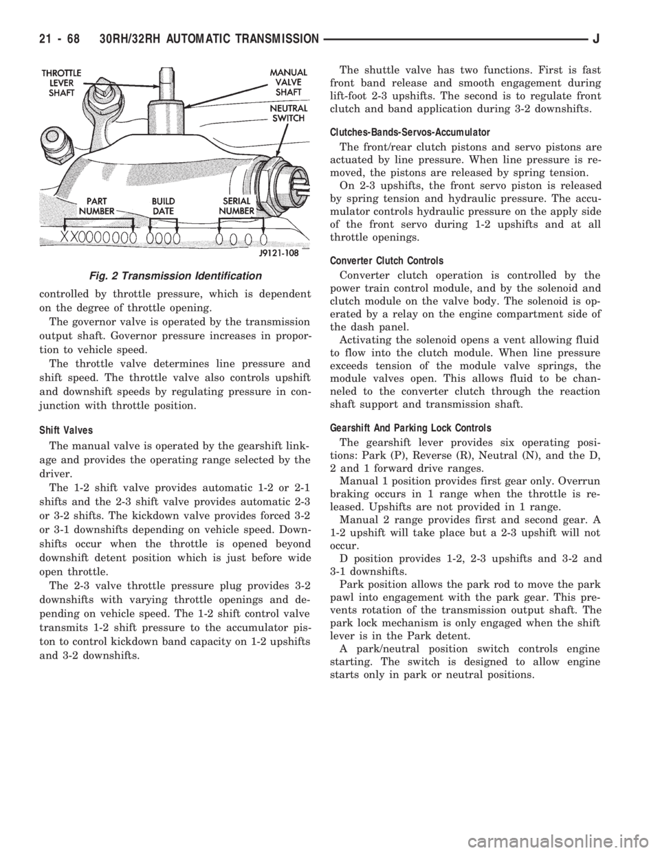
Fig. 2 Transmission Identification
21 - 68 30RH/32RH AUTOMATIC TRANSMISSIONJ
Page 1183 of 1784
(5) Line pressure should be 54-60 psi (372-414
kPa) with throttle lever forward and gradually in-
crease to 90-96 psi (620-662 kPa) as lever is moved
rearward.
Test Three-Transmission In D Range
This test checks pressure regulation and con-
dition of the front and rear clutch circuits.
Both test gauges are required for this test.
(1) Connect one test gauge to line pressure port
and other gauge to front servo pressure port (Fig. 4).
Either gauge can be used at either port.
(2) Start and run engine at 1600 rpm.
(3) Move selector lever two detents rearward from
full forward position. This is D range.
(4) Read pressures on both gauges as transmission
throttle lever is moved from full forward to full rear-
ward position.
(5) Line pressure should be 54-60 psi (372-414
kPa) with throttle lever forward and gradually in-
crease as lever is moved rearward.
(6) Front servo is pressurized only in D range and
should be same as line pressure within 3 psi (21
kPa), up to downshift point.
Test Four-Transmission In Reverse
This test checks pump output, pressure regu-
lation and the front clutch and rear servo cir-
cuits. Use 300 psi Pressure Test Gauge C-3293
for this test.
(1) Connect pressure test gauge to rear servo port
(Fig. 5).
(2) Start and run engine at 1600 rpm for test.
(3) Move valve body selector lever four detents
rearward from full forward position. This is Reverse
range.
(4) Move throttle lever all way forward then all the
way rearward and note gauge readings.
(5) Pressure should be 145 - 175 psi (1000-1207
kPa) with lever forward and increase to 230 - 280 psi
(1586-1931 kPa) as lever is moved rearward.
Test Five-Governor Pressure
This test checks governor operation by mea-
suring governor pressure response to changes
in engine speed. It is usually not necessary to
check governor operation unless shift speeds
are incorrect or if the transmission will not
shift up or down. Use 100 psi Pressure Test
Gauge C-3292 for this test.
(1) Connect test gauge to governor pressure port
(Figs. 5 and 6).
(2) Move selector lever to D range.
(3) Apply service brakes. Start and run engine at
curb idle speed and note pressure. At idle and with
wheels stopped, pressure should be zero to 1-1/2 psi
maximum. If pressure exceeds this figure, governor
valve or weights are sticking open.(4) Slowly increase engine speed and observe
speedometer and pressure test gauge. Governor pres-
sure should increase in proportion to vehicle speed
(approximately 1 psi for every 1 mph shown on
speedometer).
(5) Governor pressure rise should be smooth and
drop back to 0 to 1-1/2 psi when throttle is closed
and wheels are stopped.
(6) Compare results of pressure tests with analysis
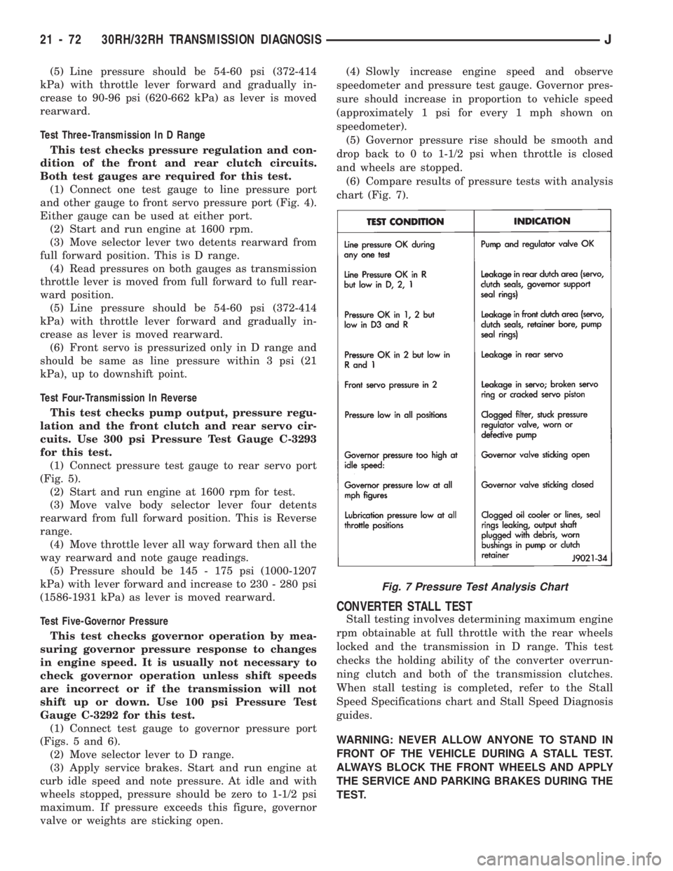
chart (Fig. 7).
CONVERTER STALL TEST
Stall testing involves determining maximum engine
rpm obtainable at full throttle with the rear wheels
locked and the transmission in D range. This test
checks the holding ability of the converter overrun-
ning clutch and both of the transmission clutches.
When stall testing is completed, refer to the Stall
Speed Specifications chart and Stall Speed Diagnosis
guides.
WARNING: NEVER ALLOW ANYONE TO STAND IN
FRONT OF THE VEHICLE DURING A STALL TEST.
ALWAYS BLOCK THE FRONT WHEELS AND APPLY
THE SERVICE AND PARKING BRAKES DURING THE
TEST.
Fig. 7 Pressure Test Analysis Chart
21 - 72 30RH/32RH TRANSMISSION DIAGNOSISJ
Page 1184 of 1784
STALL TEST PROCEDURE
(1) Connect tachometer to engine.
(2) Check and adjust transmission fluid level.
(3) Start and run engine until transmission fluid
reaches normal operating temperature.
(4) Block front wheels.
(5) Fully apply service and parking brakes.
(6) Open throttle completely for no more than five
seconds and record maximum engine rpm registered
on tachometer.
CAUTION: Stall testing causes a rapid increase in
transmission fluid temperature. Do not hold the
throttle open any longer than five seconds. If more
than one stall test is required, run the engine at
1000 rpm with the transmission in Neutral for at
least 20 seconds to cool the fluid.
(7) If engine speed exceeds maximum shown in
stall speed chart, release accelerator immediately.
This indicates that transmission clutch slippage is
occurring.
(8) Shift transmission into Neutral. Run engine for
20 seconds to cool fluid. Then stop engine, shift
transmission into Park and release brakes.
(9) Stall speeds should be in 1700-2000 rpm range.
(10) Refer to Stall Test Diagnosis.
STALL TEST DIAGNOSIS
Stall Speed Too High
If the stall speed exceeds specifications by more
than 200 rpm, transmission clutch slippage is indi-
cated.
Stall Speed Too Low
Low stall speeds with a properly tuned engine in-
dicate a torque converter overrunning clutch prob-
lem. The condition should be confirmed by road
testing prior to converter replacement.
The converter overrunning clutch is slipping when
stall speeds are 250 to 350 rpm below specified min-
imum. And when the vehicle operates properly at
highway speeds but has poor low speed acceleration.
Stall Speed Normal
If stall speeds are normal but abnormal throttle
opening is required to maintain highway speeds, the
converter overrunning clutch is seized and the torque
converter must be replaced.
Converter Noise During Test
A whining noise caused by fluid flow is normal
during a stall test. However, loud metallic noises in-
dicate a damaged converter. To confirm that noise is
originating from the converter, operate the vehicle at
light throttle in Drive and Neutral on a hoist and lis-
ten for noise coming from the converter housing.
AIR PRESSURE TEST
Air pressure testing can be used to check clutch
and band operation with the transmission either in
the vehicle, or on the work bench as a final check af-
ter overhaul.
Air pressure testing requires that the oil pan and
valve body be removed from the transmission.
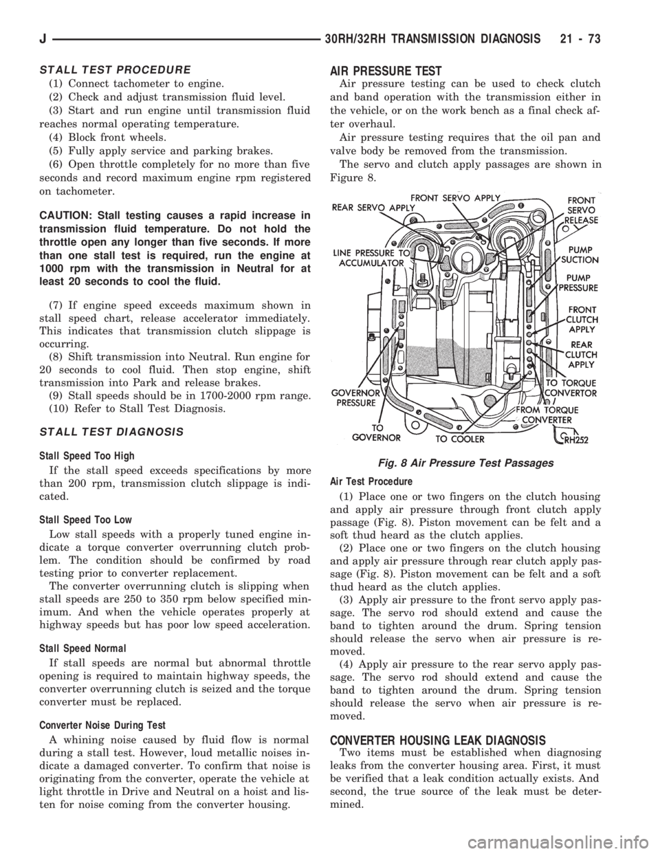
The servo and clutch apply passages are shown in
Figure 8.
Air Test Procedure
(1) Place one or two fingers on the clutch housing
and apply air pressure through front clutch apply
passage (Fig. 8). Piston movement can be felt and a
soft thud heard as the clutch applies.
(2) Place one or two fingers on the clutch housing
and apply air pressure through rear clutch apply pas-
sage (Fig. 8). Piston movement can be felt and a soft
thud heard as the clutch applies.
(3) Apply air pressure to the front servo apply pas-
sage. The servo rod should extend and cause the
band to tighten around the drum. Spring tension
should release the servo when air pressure is re-
moved.
(4) Apply air pressure to the rear servo apply pas-
sage. The servo rod should extend and cause the
band to tighten around the drum. Spring tension
should release the servo when air pressure is re-
moved.
CONVERTER HOUSING LEAK DIAGNOSIS
Two items must be established when diagnosing
leaks from the converter housing area. First, it must
be verified that a leak condition actually exists. And
second, the true source of the leak must be deter-
mined.
Fig. 8 Air Pressure Test Passages
J30RH/32RH TRANSMISSION DIAGNOSIS 21 - 73
Page 1207 of 1784
30RH/32RH IN-VEHICLE SERVICE
INDEX
page page
Checking Fluid Level and Condition........... 96
Front Band Adjustment.................... 99
Gearshift Linkage Adjustment (YJ)............ 96
Governor and Park Gear Service............ 101
Oil Filter Replacement.................... 100
Park Interlock Cable Adjustment (XJ)......... 97
Park Lock Component Replacement......... 102
Park/Neutral Position Switch Service......... 103
Rear Band Adjustment.................... 99
Recommended Fluid...................... 96
Servicing Transmission Cooler Lines and Fittings. 106
Shift Cable Adjustment (XJ)................ 97
Speedometer Service.................... 103
Transmission Cooler Flow Testing........... 106
Transmission Cooler Reverse Flushing....... 105
Transmission Throttle Cable Adjustment (XJ/YJ) . 98
Valve Body Installation................... 101
Valve Body Removal..................... 100
Valve Body Service...................... 100
RECOMMENDED FLUID
The recommended and preferred fluid for 30RH/
32RH transmissions is Mopar ATF Plus, Type 7176.
Mopar Dexron II is acceptable but should only be
used when ATF Plus is not available.
Transmission fluid capacity is approximately 17
pints (7.9 liters). This is the approximate amount of
fluid required to fill the transmission and torque con-
verter after overhaul.
CHECKING FLUID LEVEL AND CONDITION
(1) Position vehicle on flat, level surface. This is
important in obtaining an accurate fluid level check.
(2) To avoid false readings, which could produce
under or over fill condition, do not check level until
fluid is at normal operating temperature.
(3) Shift transmission into Neutral.
(4) Apply parking brakes.
(5) Operate engine at curb idle speed.
WARNING: WHEN PERFORMING UNDERHOOD OP-
ERATIONS WITH THE ENGINE RUNNING, KEEP
YOUR HANDS WELL AWAY FROM HOT OR ROTAT-
ING ENGINE COMPONENTS. DO NOT WEAR
LOOSE ARTICLES OF CLOTHING WHICH COULD
BECOME ENTANGLED IN ENGINE COMPONENTS
OR ACCESSORIES.
(6) Shift transmission through all gear ranges and
back to Neutral (leave engine running).
(7) Clean exterior of dipstick cap and fill tube be-
fore removing transmission dipstick.
(8) Remove dipstick and inspect fluid level.
²Correct level is to FULL mark
²Acceptable level is between ADD and FULL marks
(9) Check fluid condition. Fluid should be dark to
light red in color and free of dirt or debris.
(10) If fluid is discolored or smells burned but
transmission operation was OK, check cooler flow,
flush cooler and lines and change fluid and filter.
Then road test again to confirm proper operation.(11) If fluid is black or dark brown, burned/turned
to sludge, contains large quantities of metal or fric-
tion material particles, transmission will need over-
haul. Especially if problems were evident during
road test and preliminary diagnosis. Fluid cooler
should also be flow tested and flushed if necessary.
GEARSHIFT LINKAGE ADJUSTMENT (YJ)
(1) Check linkage adjustment by starting engine in
Park and Neutral.
(2) Adjustment is OK if engine starts only in park
and Neutral. Adjustment is incorrect if engine starts
in one but not both positions.
(3) If engine starts in any position other than Park
or Neutral, or if engine will not start at all, park/
neutral position switch may be faulty.
(4) Shift transmission into Park.
(5) Raise vehicle.
(6) Check condition of shift rods, bellcrank, bell-
crank brackets and linkage bushings/grommets (Fig.
1). Tighten, repair, replace worn, damaged parts. Do
not attempt adjustment if linkage components are
worn or damaged.
(7) Loosen shift rod trunnion lock bolt or nut. Be
sure upper shift rod slides freely in trunnion (Fig. 1).
Also be sure shift rods and bellcrank rotate freely
and do not bind at any point.
(8) Verify that manual lever is in Park detent
(Fig. 1). Move lever all the way rearward to be sure
it is in Park.
(9) Check for positive engagement of park lock by
attempting to rotate propeller shaft. Shaft will not
turn when park pawl is engaged.
(10) Adjust shift rod trunnion to a obtain free pin
fit in bellcrank arm and tighten trunnion lock bolt or
nut. Prevent shift rod from turning while tightening
bolt or nut. Gearshift linkage lash must be elimi-
nated to obtain proper adjustment. Eliminate lash by
pulling downward on shift rod and pressing upward
on bellcrank.
21 - 96 30RH/32RH IN-VEHICLE SERVICEJ