1993 DODGE TRUCK radiator
[x] Cancel search: radiatorPage 1087 of 1502
21 - 86
AUTOMATIC
TRANSMISSION-32RH/36RH/37RH/42RH/46RH
•
(6)
Remove dipstick and check fluid
level
as fol
lows:
(a) Dipstick has three fluid level indicating
marks which are a MIN dot mark, an OK mark and a MAX fill arrow mark:
(b) Correct level is to MAX arrow nark on dip
stick. This is correct maximum hot fluid level. Ac
ceptable level is between OK mark and max arrow
mark on dipstick.
(c) If level is at, or below MIN level dot on dip
stick, add only enough fluid to restore correct level.
Mopar ATF Plus, type 7176 is the preferred fluid.
Mopar Dexron II can be used if ATF Plus is not
readily available.
CAUTION:
Do not
overfill
the
transmission.
Overfill
ing
may
cause
leakage out the
pump
vent which
can
be mistaken for a
pump
seal
leak. In addition,
overfilling
will
also
cause
fluid
aeration
and
foam
ing
as the
excess
fluid is picked up and churned by
the
gear
train.
This
will
significantly
reduce fluid
life.
(7) Check and note fluid condition as follows: (a) Fluid should be dark to light red in color and
free of particles and sludge.
(b) If fluid is orange, brown, or smells slightly
burned, flow test and reverse flush cooler and lines. Then change fluid and filter and road test again to
confirm proper operation.
(c) If fluid is black, dark brown, turned to sludge,
contains extensive amount of metal or friction ma
terial particles, transmission will need overhaul. Main and auxiliary coolers will have to be flow
tested and reverse flushed as well.
Effects
Of Incorrect Fluid Level A low fluid level allows the pump to take in air
along with the fluid. Air in the fluid will cause fluid
pressures to be low and develop slower than normal.
If the transmission is overfilled, the gears churn
the fluid into foam, aerating the fluid and causing
the same conditions that occur with a low level.
In either case, air bubbles cause fluid overheating,
oxidation and varnish buildup which interferes with
valve, clutch and servo operation. Foaming also causes fluid expansion which can result in fluid over
flow from the transmission vent or fill tube. Fluid
overflow can easily be mistaken for a leak if inspec
tion is not careful.
FLUID
CONTAMINATION
Transmission fluid contamination is generally a re
sult of:
• adding incorrect fluid
• failure to clean dipstick and fill tube when check ing level
• engine coolant entering the fluid • internal failure that generates debris
• overheat that generates sludge (fluid breakdown)
• failure to reverse flush cooler and lines after re
pair
• failure to replace contaminated converter after re
pair
The use of non recommended fluids can result in
transmission failure. The usual results are erratic
shifts,
slippage, abnormal wear and eventual failure
due to fluid breakdown and sludge formation. Avoid
this condition by using recommended fluids only.
The dipstick cap and fill tube should be wiped
clean before checking fluid level. Dirt, grease and
other foreign material on the cap and tube could fall
into the tube if not removed beforehand. Take the
time to wipe the cap and tube clean before withdraw ing the dipstick.
Engine coolant in the transmission fluid is gener
ally caused by a cooler malfunction. The only remedy
is to replace the radiator as the cooler in the radiator
is not a serviceable part. If coolant has circulated
through the transmission for some time, an overhaul may also be necessary; especially if shift problems
had developed.
The transmission cooler and lines should be reverse
flushed whenever a malfunction generates sludge and/or debris. The torque converter should also be re
placed at the same time.
Failure to flush the cooler and lines will result in
re-contamination and a shop comeback. Flushing ap
plies to auxiliary coolers as well. The torque con verter should also be replaced whenever a failure
generates sludge and debris. This is necessary be
cause normal converter flushing procedures will not
remove al of the contaminants.
OVERDRIVE
FOURTH
GEAR
ELECTRICAL
CONTROLS
The electrical controls governing the shift into
fourth gear consist of the control switch on the in strument panel and the overdrive solenoid on the
valve body. The control switch is in circuit with the solenoid and must be in the On position to energize
the solenoid. The transmission must also have
reached third gear range before the shift to fourth gear will occur. The control switch, valve body solenoid, case con
nectors and related wiring can all be tested with a 12
volt test lamp or a multimeter. Check continuity of each component when diagnosis indicates this is nec
essary. Switch and solejioid continuity should be checked
whenever the transmission fails to shift into fourth
gear range.
THROTTLE
VALVE
CABLE
Throttle valve cable adjustment is important to
proper operation. This adjustment positions the
Page 1104 of 1502
•
AUTOMATIC
TRANSMISSION—32RH/36RH/37RH/42RH/46RH
21-103
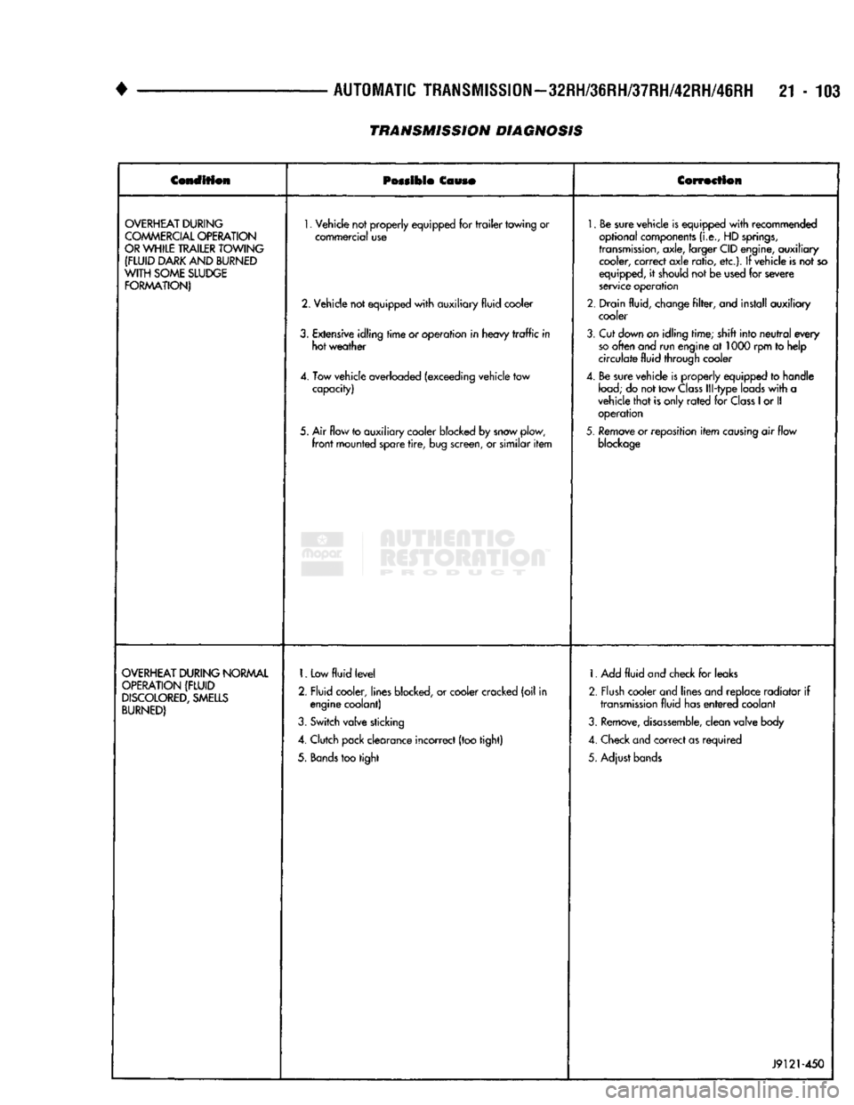
TRANSMISSION DIAGNOSIS
Condition
Possible
Couso
Correction
OVERHEAT
DURING
COMMERCIAL
OPERATION
OR
WHILE
TRAILER
TOWING
(FLUID
DARK
AND
BURNED
WITH
SOME
SLUDGE
FORMATION)
1.
Vehicle not properly equipped for
trailer
towing or
commercial use
2. Vehicle not equipped
with
auxiliary fluid cooler
3.
Extensive idling
time
or operation in heavy
traffic
in hot weather
4. Tow vehicle overloaded (exceeding vehicle tow capacity)
5. Air flow to auxiliary cooler blocked by snow plow,
front
mounted spare
tire,
bug screen, or similar
item
1.
Be sure vehicle is equipped
with
recommended
optional components
(i.e.,
HD
springs,
transmission,
axle, larger CID engine, auxiliary cooler, correct axle ratio, etc.). If vehicle is not so
equipped, it should not be used for severe
service operation
2. Drain fluid, change
filter,
and install auxiliary cooler
3.
Cut down on idling time; shift into
neutral
every
so
often and run engine at 1000 rpm to help
circulate fluid through cooler
4. Be sure vehicle is properly equipped to handle
load;
do not tow
Class
Ill-type loads
with
a
vehicle
that
is only
rated
for
Class
1
or II operation
5.
Remove or reposition
item
causing
air flow
blockage
OVERHEAT
DURING
NORMAL
OPERATION
(FLUID
DISCOLORED,
SMELLS
BURNED)
1.
Low
fluid
level
2. Fluid cooler, lines blocked, or cooler cracked (oil in engine coolant)
3.
Switch valve sticking
4. Clutch pack clearance incorrect (too tight)
5.
Bands
too tight 1. Add
fluid
and check for leaks
2. Flush cooler and lines and replace radiator if
transmission
fluid has
entered
coolant
3.
Remove,
disassemble,
clean valve body
4. Check and correct as required
5. Adjust bands
J9121-450
Page 1105 of 1502
21 - 104
AUTOMATIC
TRANSMISSION—32RH/36RH/37RH/42RH/46RH
•
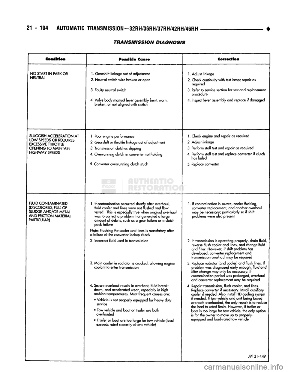
Condition
POMIOSO
Ccwse
Correction
NO
START
IN
PARK
OR
NEUTRAL
1.
Gearshift
linkage
out
of
adjustment
2.
Neutral
switch
wire
broken
or
open
3.
Faulty
neutral
switch
4.
Valve
body
manual
lever
assembly
bent,
worn,
broken,
or not
aligned
with
switch
1.
Adjust linkage
2.
Check continuity
with
test lamp; repair as required
3.
Refer to service section for test and replacement procedure
4.
inspect lever
assembly
and replace if damaged
SLUGGISH
ACCELERATION
AT
LOW
SPEEDS
OR
REQUIRES
EXCESSIVE
THROTTLE
OPENING
TO MAINTAIN
HIGHWAY
SPEEDS
1.
Poor
engine
performance
2.
Gearshift
or
throttle
linkage
out of adjustment
3.
Transmission
clutches slipping
4.
Overrunning clutch in converter not holding
5. Converter overrunning clutch stuck
1.
Check engine and repair as required
2. Adjust linkage
3. Perform stall test and repair as required
4.
Perform stall test and replace converter if clutch
has
failed
5. Replace converter
FLUID
CONTAMINATED
(DISCOLORED,
FULL
OF
SLUDGE
AND/OR
METAL
AND
FRICTION
MATERIAL
PARTICULAR)
1.
If contamination occurred shortly
after
overhaul,
fluid cooler and
lines
were
not
flushed
and flow rested. This is especially
true
when original overhaul
was
to correct a problem
that
generated a large
amount of debris,
such
as a gear
failure
or a clutch
pack
failure
Note: Flushing the cooler and lines is mandatory
after
a
failure
of the converter lockup clutch
2.
Incorrect fluid used in transmission
3. Main cooler in radiator is cracked, allowing engine coolant to
enter
transmission
4.
Severe overload results in overheat, fluid break
down,
and accelerated wear, especially in high
ambient temperatures.
Most
frequent
causes
are:
• Vehicle is not properly equipped for heavy duty
service
• Tow vehicle and boat or
trailer
are both overloaded
•
Trailer
or boat are too large for tow vehicle (load exceeds rated capacity of tow vehicle)
1.
If contamination is severe, cooler flushing,
converter replacement, and another overhaul may be
necessary;
particularly so if shift
problems
were
also
present
2.
If
transmission
is operating properly, drain fluid, reverse flush cooler and lines, and change fluid
and
filter.
However, if shift problem has
developed, converter replacement and
transmission
overhaul may be required
3.
Replace radiator (and cooler) and flush lines. If problem was
diagnosed
early
enough,
fluid and
filter
change
may
only
be
necessary.
If
contamination perioa was prolonged, overhaul
and
converter replacement may be required
4.
Repair
transmission,
flush cooler, and lines.
Replace
converter if
necessary.
Install auxiliary
cooler if needed.
Also
install HD cooling system if needed. If tow vehicle and unit being towed
are both overloaded, the only repair is to reduce
the load to
rated
limits. However, if
trailer
or boat is too large for tow vehicle, the only option
is
for the owner to move up to properly-
equipped and load-rated tow vehicle
J9121-449
TRANSMISSION DIAGNOSIS
Page 1142 of 1502
•
IN-VEHICLE
SERVICE-32RH/36RH/37RH/42RH/46RH
21 - 141 (2) Position drain pan under cooler pressure line to
catch material flushed through cooler and lines. (3) Reverse flush cooler using hand operated suc
tion gun filled with mineral spirits. Insert gun nozzle (or hose) into cooler return line. Then force mineral
spirits into line and through cooler. (4) Continue reverse flushing until fluid exiting
cooler pressure line is clear and free from debris. Re
place cooler if fluid cannot be pumped through. (5) Clear flushing materials from cooler and lines
with short pulses of compressed air. Insert air gun nozzle into cooler return line and continue short air pulses until all fluid is cleared from cooler and lines. (6) Pump one quart of fresh automatic transmission
fluid through cooler and lines before reconnecting lines.
CHECKING COOLER FLUID FLOW Cooler flow is checked, by measuring the amount of
fluid pumped through the cooler in a specified time
by the transmission oil pump. (1) Disconnect cooler return line from transmission
and place it in one quart test container.
(2) Add extra quart of fluid to transmission.
(3) Use stopwatch to check test time.
(4) Shift into Neutral.
(5) Start and run engine at curb idle speed and
note cooler flow. A minimum of one quart (0.9 liter)
of fluid should flow into test container in 20 seconds. (6) If fluid flow is intermittent, flows less than one
quart in 20 seconds, or fails to flow at all, cooler is
plugged or damaged and should be replaced.
MAIN COOLER REPLACEMENT The main transmission cooler is located in the ra
diator lower tank. The cooler is not a serviceable component. If the cooler is damaged in any way, the
radiator will have to be replaced.
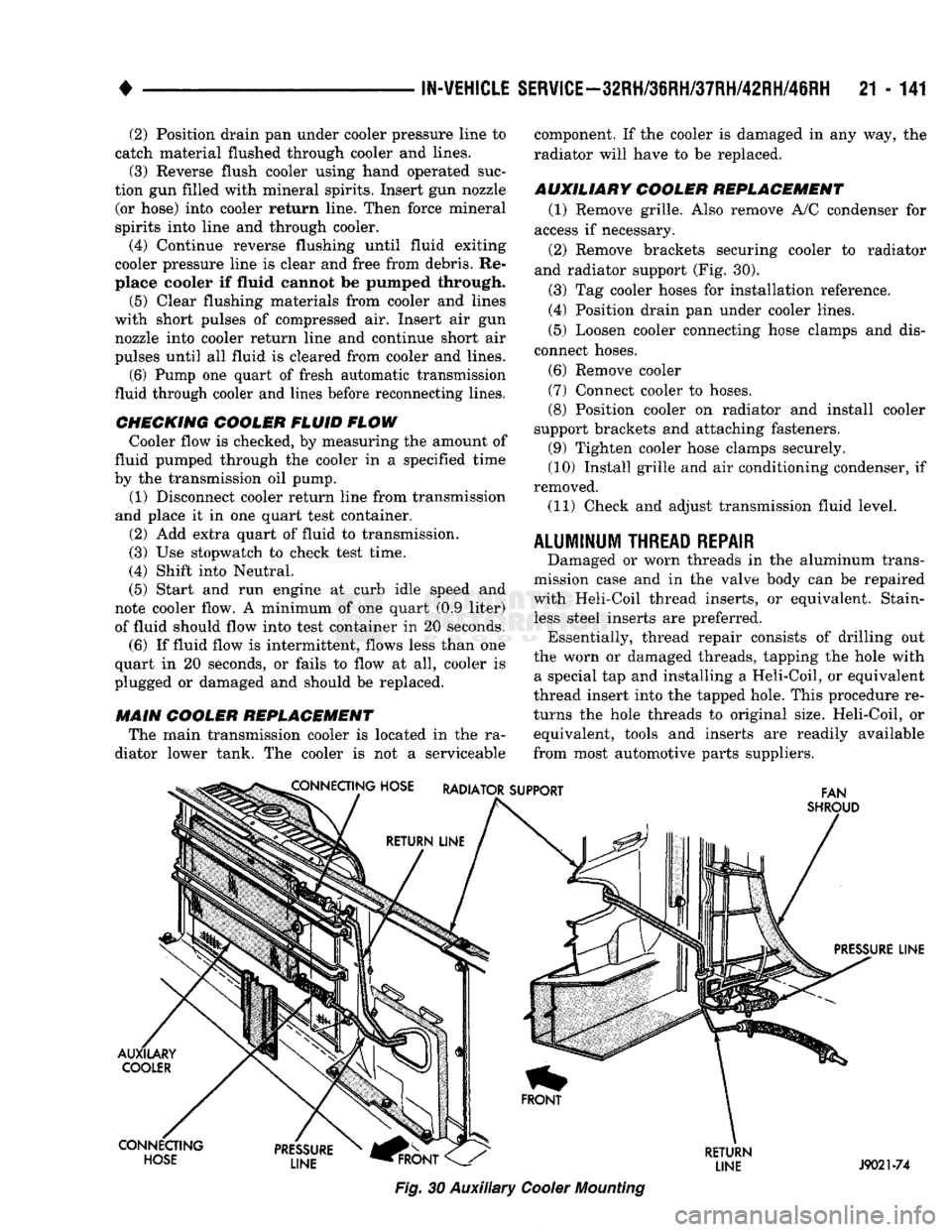
AUXILIARY COOLER REPLACEMENT (1) Remove grille. Also remove A/C condenser for
access if necessary.
(2) Remove brackets securing cooler to radiator
and radiator support (Fig. 30).
(3) Tag cooler hoses for installation reference.
(4) Position drain pan under cooler lines.
(5) Loosen cooler connecting hose clamps and dis
connect hoses.
(6) Remove cooler
(7) Connect cooler to hoses.
(8) Position cooler on radiator and install cooler
support brackets and attaching fasteners. (9) Tighten cooler hose clamps securely.
(10) Install grille and air conditioning condenser, if
removed.
(11) Check and adjust transmission fluid level.
ALUMINUM
THREAD
REPAIR
Damaged or worn threads in the aluminum trans
mission case and in the valve body can be repaired
with Heli-Coil thread inserts, or equivalent. Stain less steel inserts are preferred. Essentially, thread repair consists of drilling out
the worn or damaged threads, tapping the hole with a special tap and installing a Heli-Coil, or equivalent
thread insert into the tapped hole. This procedure re
turns the hole threads to original size. Heli-Coil, or equivalent, tools and inserts are readily available
from most automotive parts suppliers. CONNECTING HOSE RADIATOR SUPPORT
FAN
SHROUD
PRESSURE LINE
AUXILARY COOLER
CONNECTING HOSE PRESSURE
LINE
HFRONT
Fig.
30 Auxiliary
Cooler
Mounting
RETURN
LINE J9021-74
Page 1384 of 1502
•
BODY
COMPONENTS
23 - 1
CONTENTS
page
page
CAB/BODY
INTERIOR COMPONENTS
35
FIXED
GLASS
. 29
DOORS
21
PAINT
CODE
CHART
54
EXTERIOR
COMPONENTS
1
REFINISHING
PROCEDURES
54
EXTERIOR COMPONENTS
INDEX
page
Battery
Tray
7
Blower Motor Housing
Insulation
Panel—Diesel
Engine
Only
7
Body
Mouldings, Nameplates
and
Decals .......
9
Cab
. 14
Cab/Body
and
Cargo
Box
Stripes
11
Cargo
Box
19
Cowl
Grille
7
Front
Fenders
8
Fuel
Filler
Door
and
Nozzle/Tubes
12
Grille
and
Grille
Extension Panel
1
Grille
Extension Panel Support Bracket
(With
Diesel Engine Only)
3
page
Grille
Opening Panel (GOP)
and
Radiator Support Panel
3
Hatchgate
and
Components
16
Hood
5
Hood
Inside Release Cable
5
Hood
Latch
4
Labels/Decals/Plates
1
Outside Mirrors
13
Roof
Vent—Ramcharger
. 20
Splash
Shields—Front Fender
9
Sport
Bar
18
Tailgate
14
LABELS/DECALS/PLATES
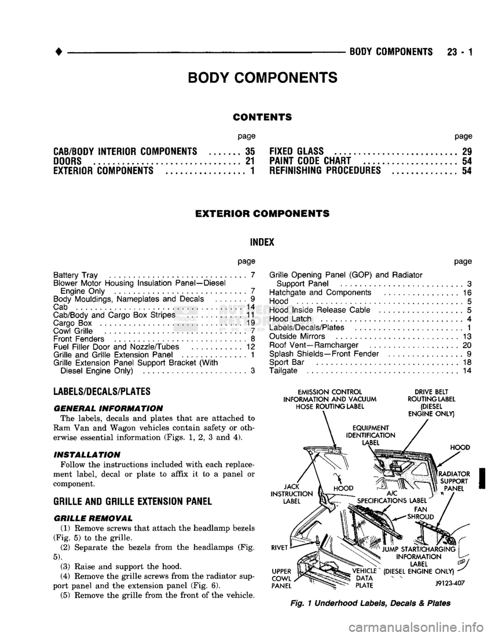
GENERAL
INFORMATION The labels, decals
and
plates that
are
attached
to
Ram Van
and
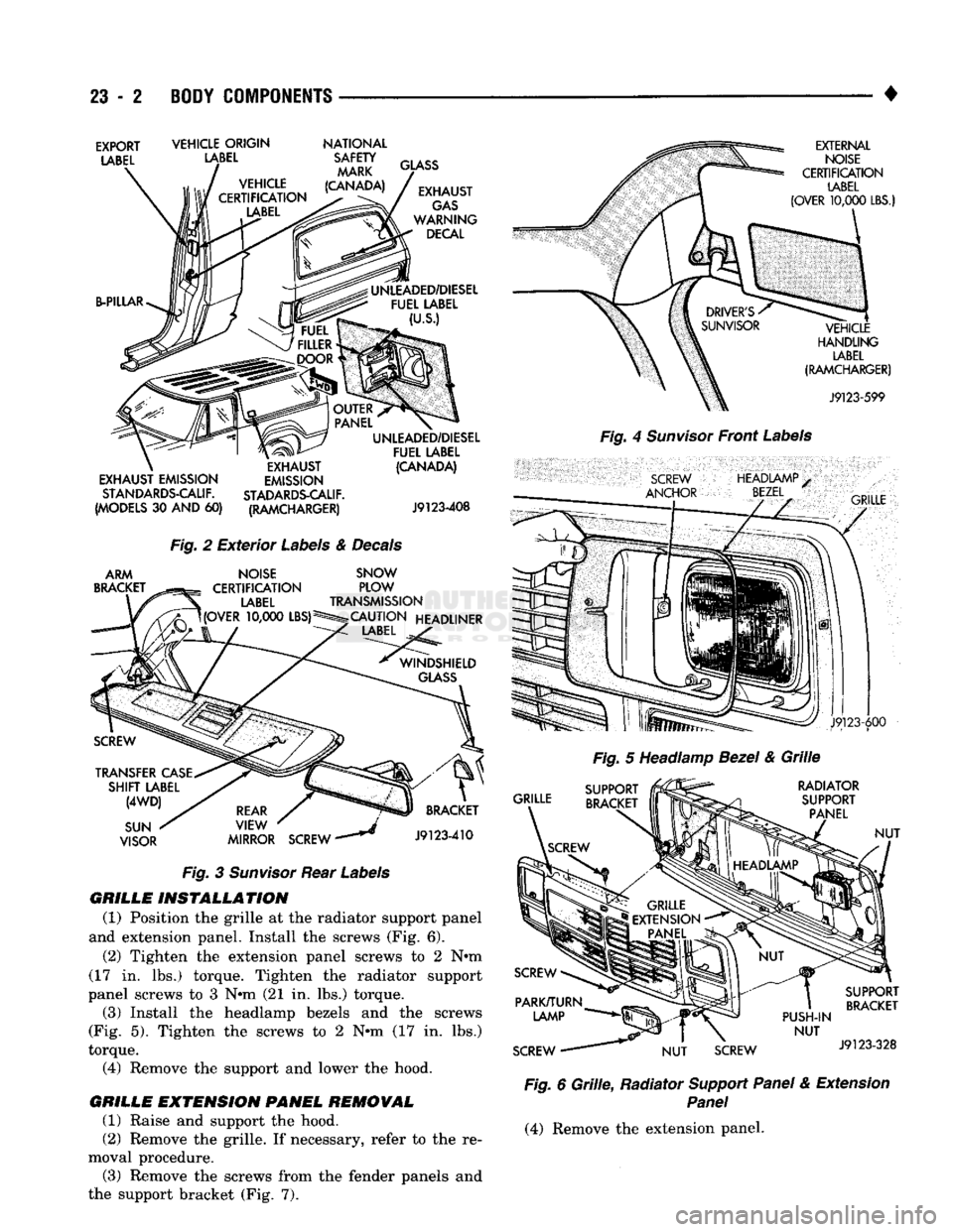
Wagon vehicles contain safety
or
oth erwise essential information (Figs.
1, 2, 3 and 4).
INSTALLATION
Follow the instructions included with each replace
ment label, decal
or
plate
to
affix
it to a
panel
or
component.
GRILLE
AND GRILLE EXTENSION PANEL
GRILLE
REMOVAL (1) Remove screws that attach the headlamp bezels
(Fig.
5) to the
grille.
(2)
Separate
the
bezels from
the
headlamps
(Fig.
5).
(3) Raise
and
support
the
hood.
(4) Remove the grille screws from the radiator sup
port panel
and the
extension panel (Fig.
6).
(5) Remove
the
grille from the front
of
the vehicle.
EMISSION
CONTROL
DRIVE
BELT
INFORMATION
AND
VACUUM
ROUTING
LABEL
HOSE
ROUTING
LABEL
(DIESEL
Fig.
1 Underhood Labels, Decals & Plates
BODY
COMPONENTS
Page 1385 of 1502
23
- 2
BODY COMPONENTS
•
EXPORT
LABEL
VEHICLE ORIGIN
LABEL
NATIONAL
SAFETY MARK
(CANADA) B-PILLAR
GLASS
EXHAUST
GAS
WARNING DECAL
UNLEADED/DIESEL FUEL LABEL
(U.S.)
EXHAUST EMISSION STANDARDS-CALIF.
(MODELS
30 AND 60)
EXHAUST
EMISSION
STADARDS-CALIF. (RAMCHARGER) UNLEADED/DIESEL
FUEL LABEL (CANADA)
J9123-408
Fig.
2
Exterior
Labels
&
Decals
ARM
BRACKET
NOISE
CERTIFICATION
LABEL
UOVER
10,000
LBS)5 SNOW
PLOW
TRANSMISSION
CAUTION HEADLINER
LABEL
TRANSFER
CASE
SHIFT
LABEL
(4WD)
SUN
VISOR
REAR
VIEW
MIRROR SCREW
*
BRACKET
J9123-410
Fig.
3
Sunvisor
Rear
Labels
GRILLE INSTALLATION
(1) Position
the
grille
at the
radiator support panel
and extension panel. Install
the
screws
(Fig. 6).
(2) Tighten
the
extension panel screws
to 2 N»m
(17
in. lbs.)
torque. Tighten
the
radiator support
panel screws
to 3 Nnn (21 in. lbs.)
torque. (3) Install
the
headlamp bezels
and the
screws
(Fig.
5).
Tighten
the
screws
to 2 Nnn (17 in. lbs.)
torque. (4) Remove
the
support
and
lower
the
hood.
GRILLE EMTENSION PANEL REMOVAL (1) Raise
and
support
the
hood.
(2) Remove
the
grille.
If
necessary, refer
to the re
moval procedure. (3) Remove
the
screws from
the
fender panels
and
the support bracket
(Fig. 7).
EXTERNAL
NOISE
CERTIFICATION
LABEL
(OVER
10,000
LBS.)
VEHICLE
HANDLING
LABEL
(RAMCHARGER)
J9123-599
Fig.
4
Sunvisor
Front
Labels
SCREW
ANCHOR
HEADIAMP
BEZEL
•
GRILLE
J9123-600
Fig.
5
Headlamp
Bezel
&
Grille
GRILLE RADIATOR
SUPPORT PANEL
NUT
PUSH-IN
NUT
SCREW
NUT
SCREW SUPPORT
BRACKET
J9123-328
Fig.
6
Grille,
Radiator
Support Panel
&
Extension
Panel
(4) Remove
the
extension panel.
Page 1386 of 1502
•
BODY
COMPONENTS
23 - 3
GRILLE
EXTENSION
PANEL
INSTALLATION
(1) Position the grille extension panel at the fender
panels and the support bracket. (2) Install the panel screws. Tighten the screws to
23 N*m (200 in. lbs.) torque.
(3) Install the grille. If necessary, refer to the in
stallation procedure. (4) Remove the support and close the hood.
U-NUT
RADIATOR GRILLE
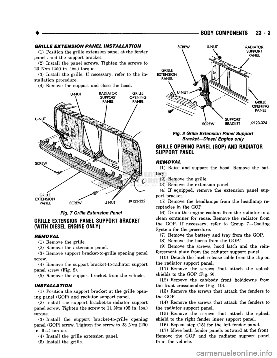
Fig. 7 Grille Extension Panel
GRILLE EXTENSION PANEL SUPPORT BRACKET
(WITH
DIESEL ENGINE ONLY)
REMOWAL
(1) Remove the grille.
(2) Remove the extension panel.
(3) Remove support bracket-to-grille opening panel
screw. (4) Remove the support bracket-to-radiator support
panel screw (Fig. 8). (5) Remove the support bracket from the vehicle.
INSTALLATION
(1) Position the support bracket at the grille open
ing panel (GOP) and radiator support panel. (2) Install the support bracket-to-radiator support
panel screw. Tighten the screw to 11 N*m (95 in. lbs.) torque.
(3) Install the support bracket-to-grille opening
panel (GOP) screw. Tighten the screw to 23 N-m (200 in. lbs.) torque.
(4) Install the grille extension panel.
(5) Install the grille.
SCREW
U-NUT
RADIATOR
Fig. 8 Grille Extension Panel Support Bracket—Diesel Engine only
GRILLE OPENING PANEL
(GOP) AND
RADIATOR
SUPPORT
PANEL
REMOVAL
(1) Raise and support the hood. Remove the bat
tery. (2) Remove the grille.
(3) Remove the extension panel.
(4) If equipped, remove the extension panel sup
port bracket.
(5) Remove the headlamps from the headlamp re
ceptacles in the GOP.
(6) Drain the engine coolant from the radiator in a
clean container for reuse. Remove the radiator from
the GOP. If necessary, refer to Group 7—Cooling System for the procedure.
(7) Remove the battery and tray from the GOP.
(8) Remove the horns from the GOP.
(9) Remove the screws, hood latch and the rein
forcement plate from the radiator support panel. (10) Detach the latch release cable from the clip on
the radiator support panel.
(11) Remove the screws that attach the splash
shields to the GOP (Fig. 9). (12) Remove the cab/body front holddowns from
the front crossmember (Fig. 10). (13) Remove the screws that attach the fenders to
the GOP.
(14) Remove the screws that attach the fenders to
the radiator support panel.
(15) Remove the screws that attach the splash
shield to the right fender inner support panel.
(16) Repeat step (15) for the left fender panel.
(17) Move both fender panels outward at the front.
Remove the GOP and the radiator support panel
from the vehicle.
Page 1387 of 1502
23
- 4
BODY
COMPONENTS
• INSTALLATION
(1) If necessary, install U-nuts at the GOP lower
flange. (2) Move both fender panels outward at the front.
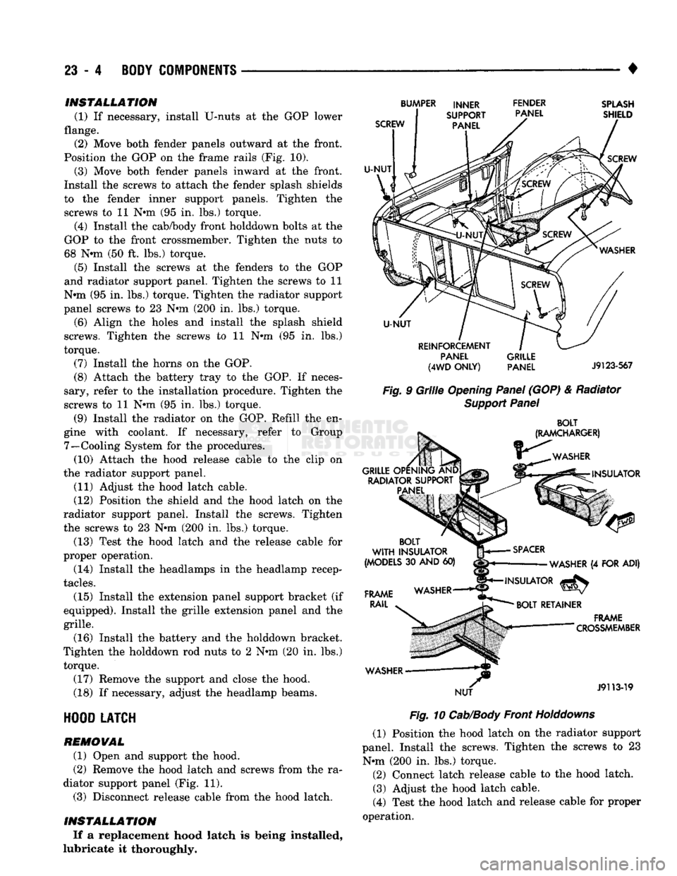
Position the GOP on the frame rails (Fig. 10).
(3) Move both fender panels inward at the front.
Install the screws to attach the fender splash shields
to the fender inner support panels. Tighten the
screws to 11 N#m (95 in. lbs.) torque.
(4) Install the cab/body front holddown bolts at the
GOP to the front crossmember. Tighten the nuts to
68 Nnn (50 ft. lbs.) torque.
(5) Install the screws at the fenders to the GOP
and radiator support panel. Tighten the screws to 11
N»m (95 in. lbs.) torque. Tighten the radiator support
panel screws to 23 Nnn (200 in. lbs.) torque.
(6) Align the holes and install the splash shield
screws. Tighten the screws to 11 N»m (95 in. lbs.)
torque.
(7) Install the horns on the GOP.
(8) Attach the battery tray to the GOP. If neces
sary, refer to the installation procedure. Tighten the
screws to 11 Nnn (95 in. lbs.) torque.
(9) Install the radiator on the GOP. Refill the en
gine with coolant. If necessary, refer to Group 7—Cooling System for the procedures. (10) Attach the hood release cable to the clip on
the radiator support panel.
(11) Adjust the hood latch cable.
(12) Position the shield and the hood latch on the
radiator support panel. Install the screws. Tighten
the screws to 23 Nnn (200 in. lbs.) torque.
(13) Test the hood latch and the release cable for
proper operation.
(14) Install the headlamps in the headlamp recep
tacles.
(15) Install the extension panel support bracket (if
equipped). Install the grille extension panel and the
grille.
(16) Install the battery and the holddown bracket.
Tighten the holddown rod nuts to 2 Nnn (20 in. lbs.) torque.
(17) Remove the support and close the hood.
(18) If necessary, adjust the headlamp beams.
HOOD
LATCH
REMOVAL
(1) Open and support the hood.
(2) Remove the hood latch and screws from the ra
diator support panel (Fig. 11). (3) Disconnect release cable from the hood latch.
INSTALLATION If a replacement hood latch is being installed,
lubricate it thoroughly.
SCREW
U-NUT
BUMPER INNER FENDER
SUPPORT PANEL
PANEL
SPLASH
SHIELD
SCREW
U-NUT
REINFORCEMENT PANEL
(4WD
ONLY)
GRILLE
PANEL
J9123-567
Fig.
9
Grille
Opening
Panel
(GOP) & Radiator
Support
Panel
BOLT
(RAMCHARGER)
WASHER
GRILLE OPENING AND RADIATOR SUPPORT PANEL INSULATOR
BOLT
WITH
INSULATOR
(MODELS
30
AND
60)
FRAME
RAIL
WASHER NUT
SPACER
WASHER
(4
FOR ADI)
INSULATOR
^
BOLT
RETAINER
.
FRAME
— "
"
CROSSMEMBER
J9113-19
Fig.
10
Cab/Body
Front
Holddowns
(1) Position the hood latch on the radiator support
panel. Install the screws. Tighten the screws to 23 Nnn (200 in. lbs.) torque. (2) Connect latch release cable to the hood latch. (3) Adjust the hood latch cable.
(4) Test the hood latch and release cable for proper
operation.